Y Gantry
Intro
The purpose of this work instruction is to explain the assembly process for the LumenPnP v4 Left-Side Y-Gantry (y-gantry-left). This document also serves as the work instruction for the y-gantry-right subassemby, as this is simply a mirror of the left-side.
Create Y-Gantry Subassembly
- Remove any stringing from the print with a heat gun
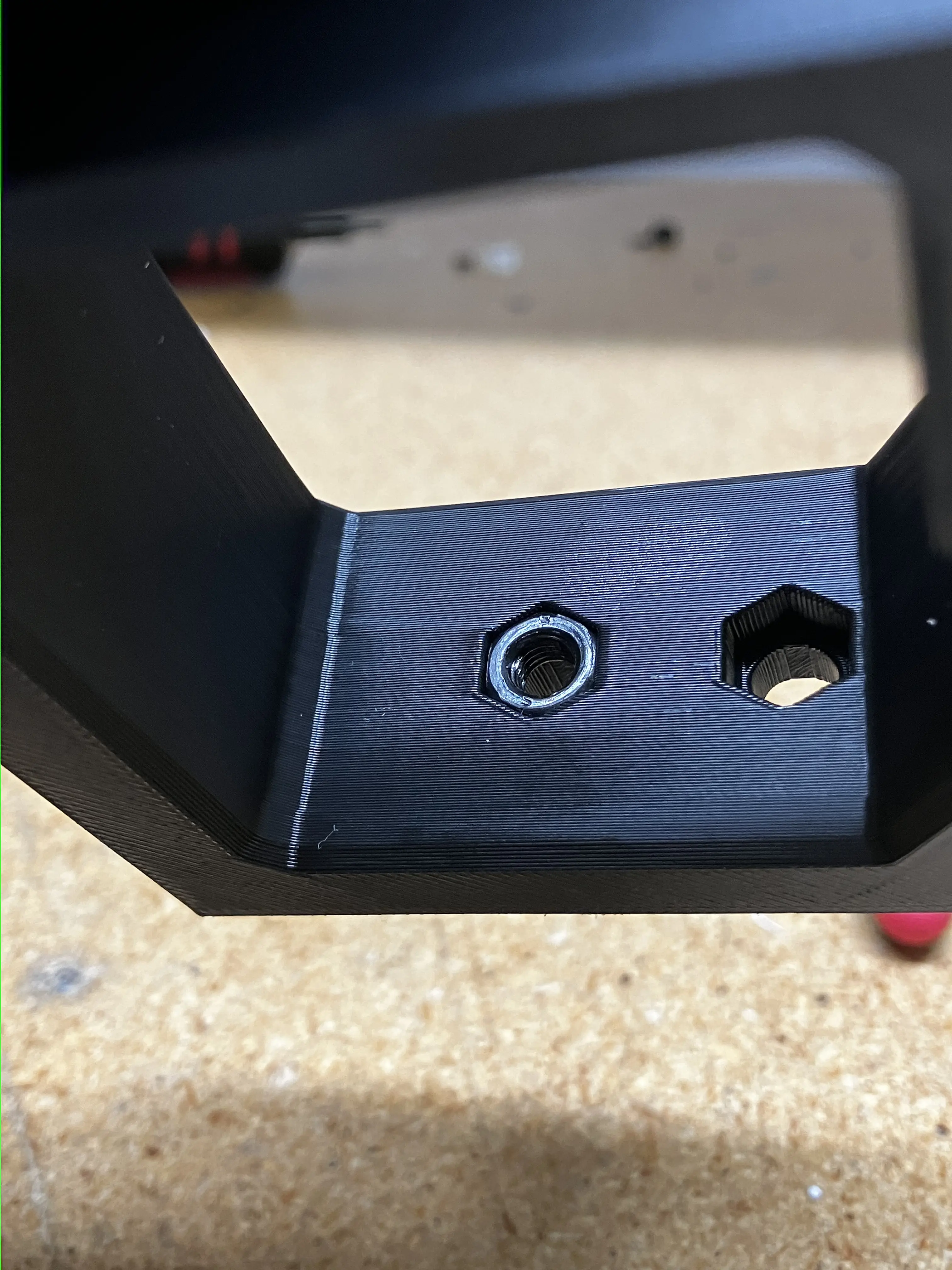
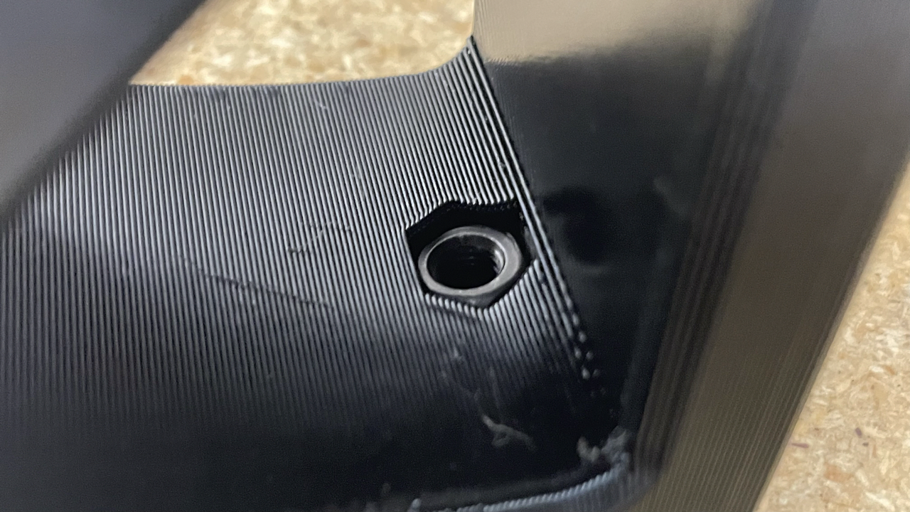
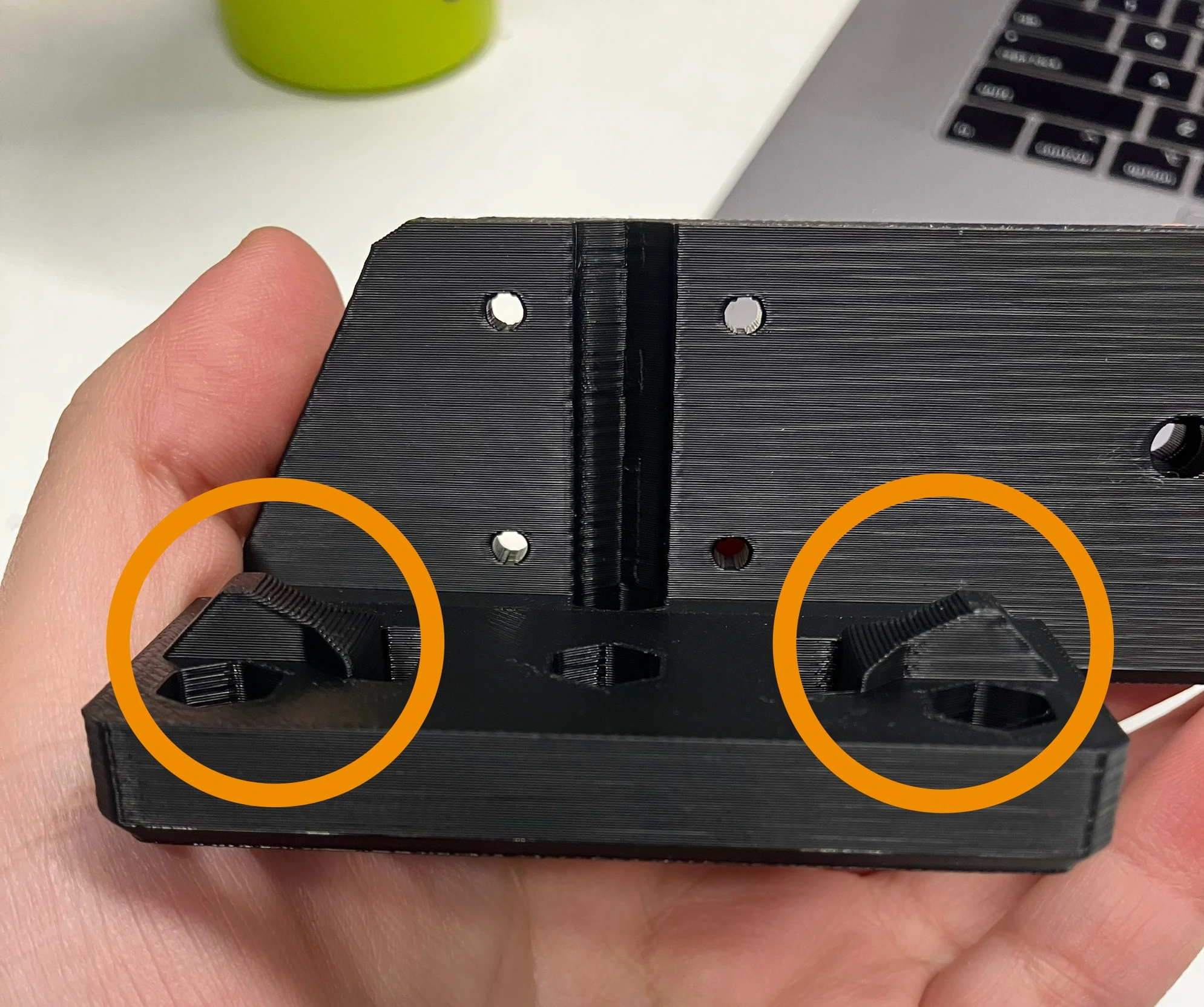
- Insert 6x
m5-hex-nutinto the following region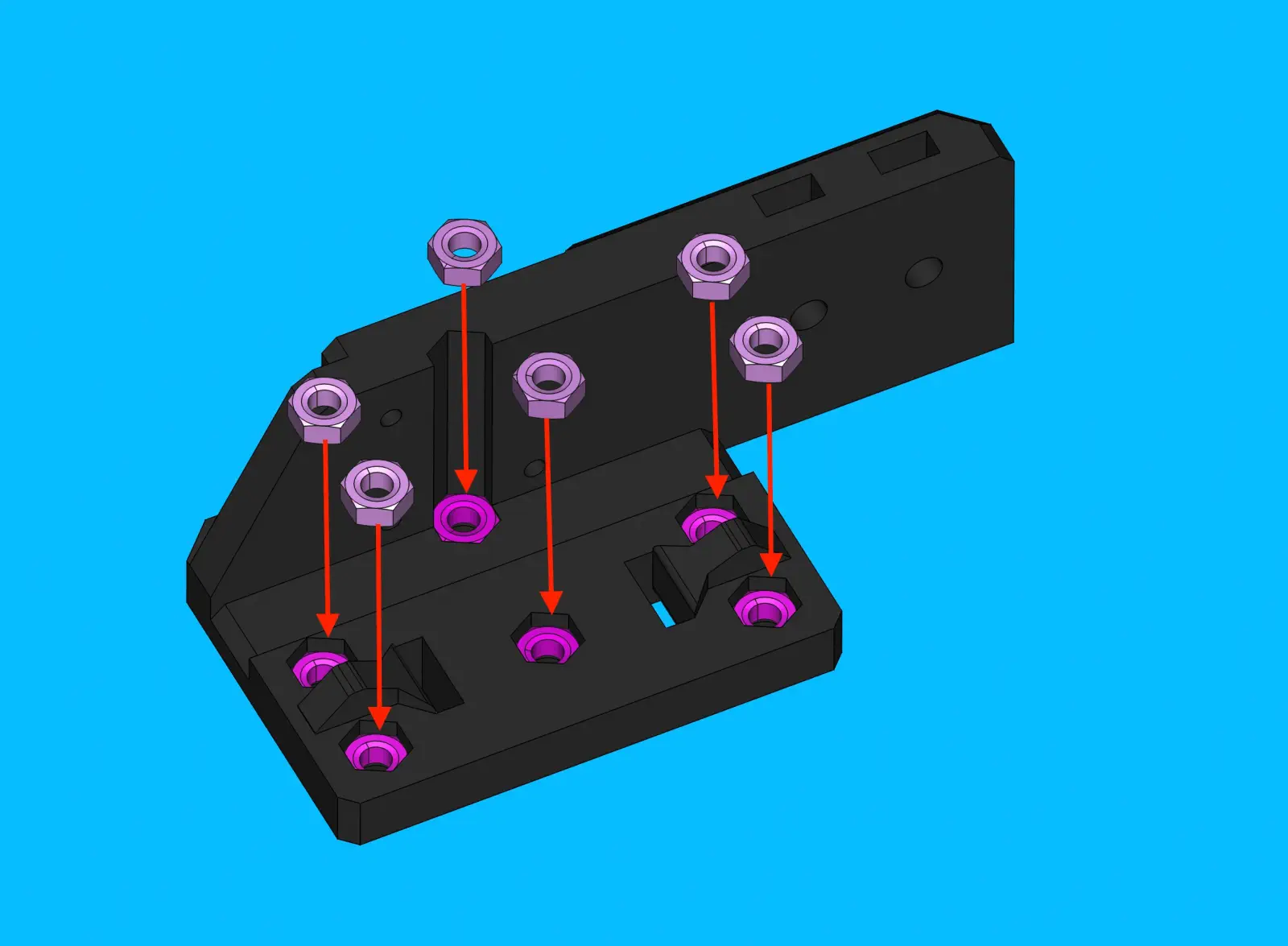
- Install 2x
m5-square-nutinto the location shown below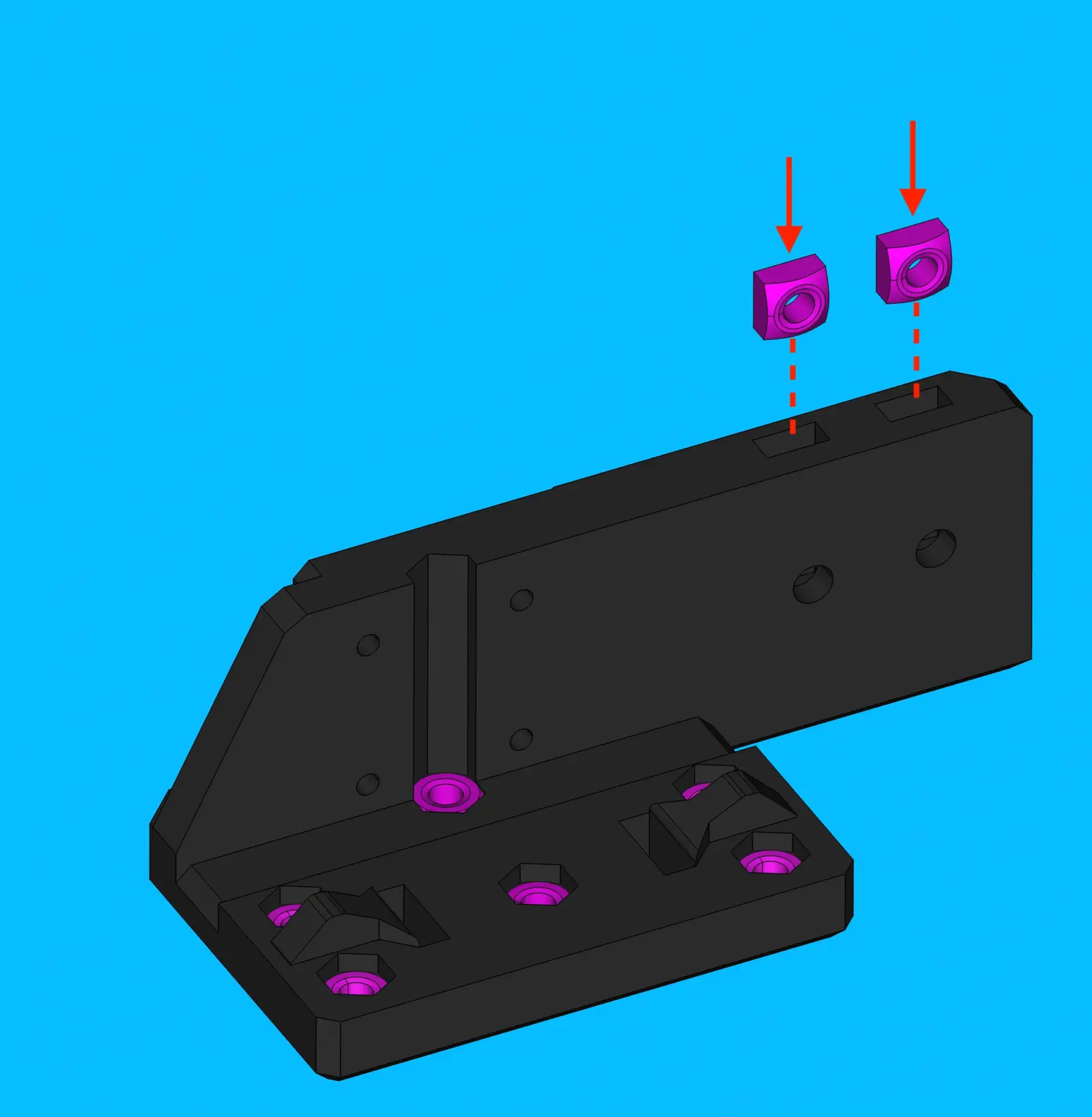
Create Front-Left-Leg Subassembly
Prepare front-left-leg
- Remove any stringing from the print with a heat gun
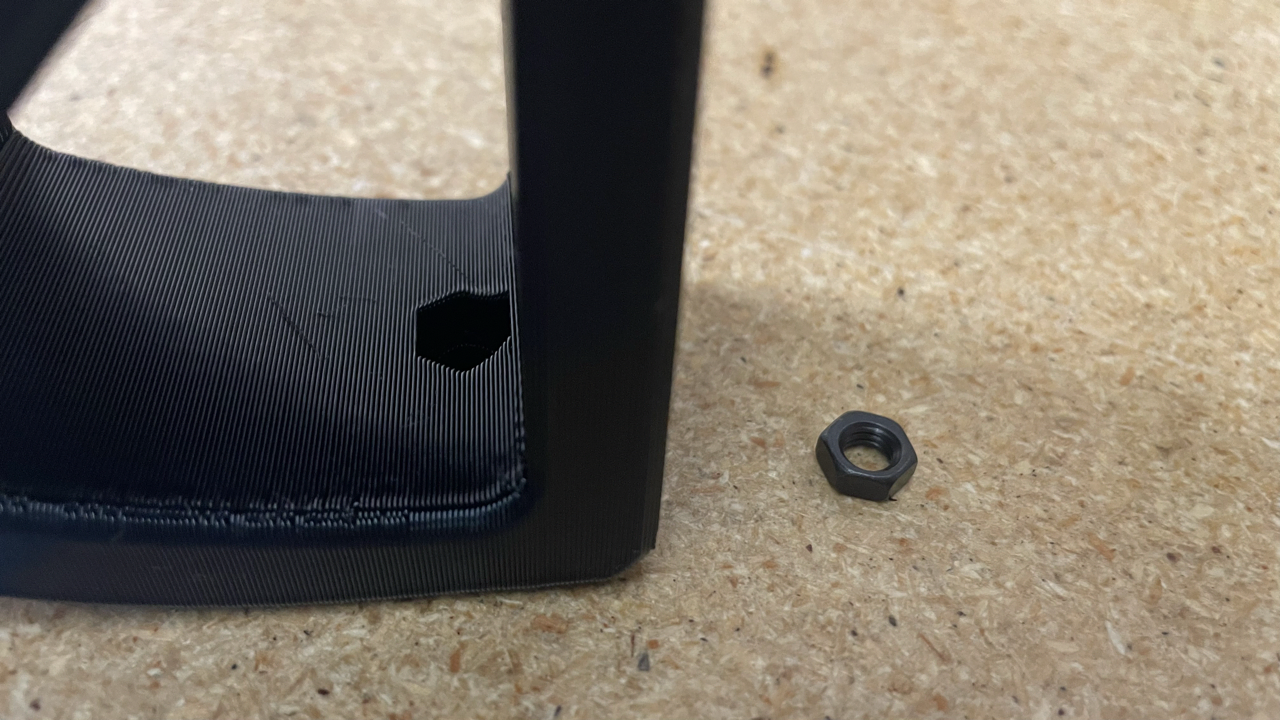
-
Insert 2x
M5-hex-nutinto bottom of leg. You can use a thick screwdriver to push part of theM5-hex-nutin and finish with theM5-hex-nut-jig, also known as thethingy.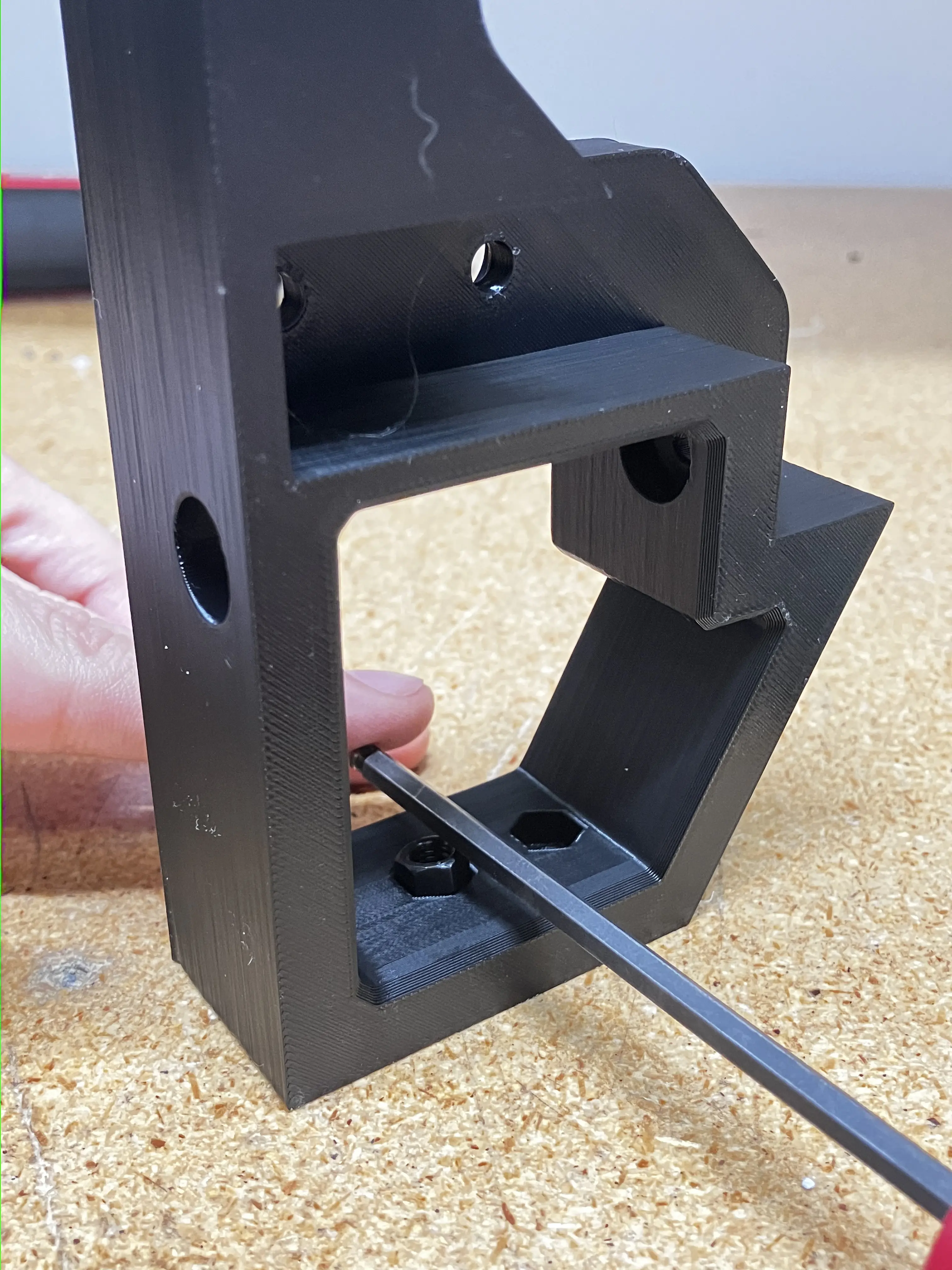
-
Insert 1x
m5-square-nutnear extrusion pocket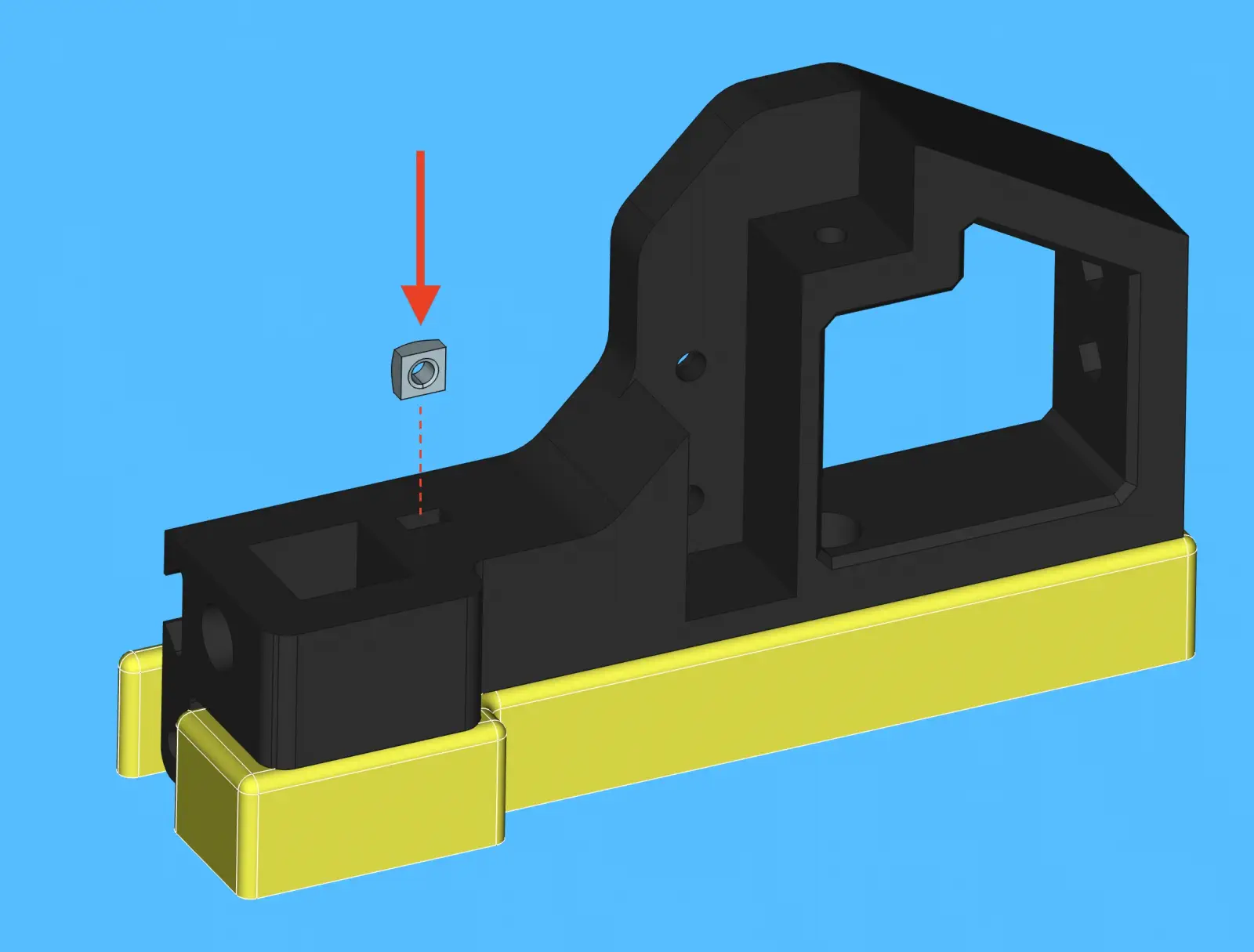
-
Insert 1x
m5-nylock-hex-nutinto in the underside ofbelt-tensioner-armmounting post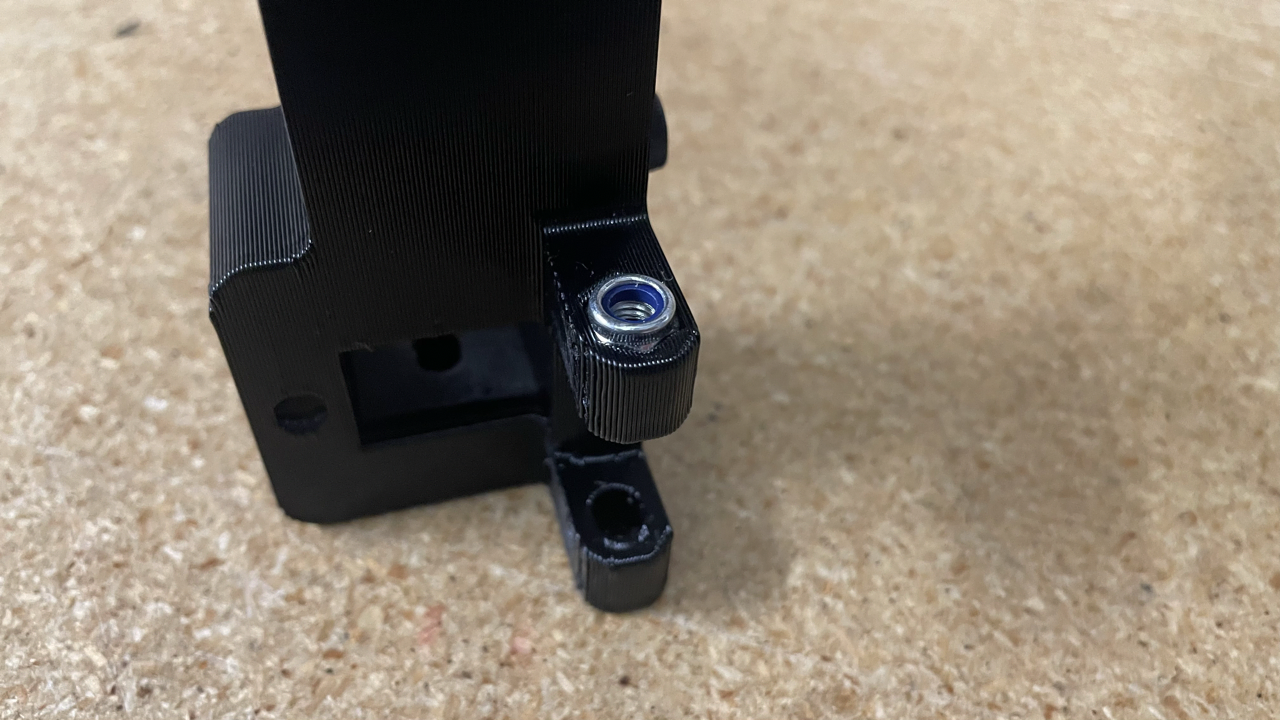
Prepare belt-tensioner-arm
- Press an
M3-hex-nutinto thebelt-tension-armwith aarbor-press-jig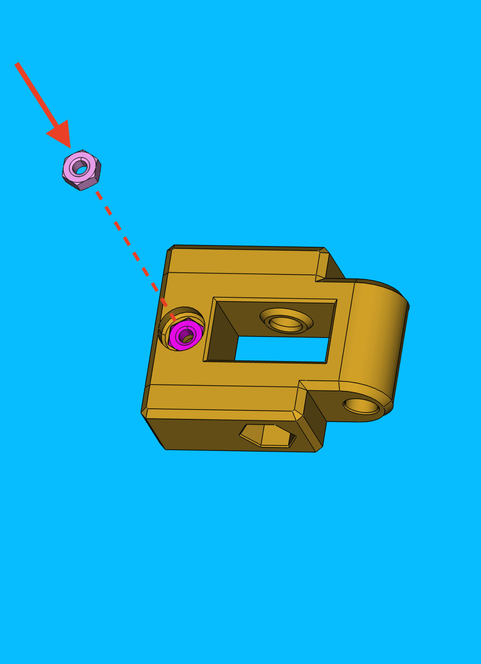
- Thread a
M3x16-boltthrough thebelt-tension-arm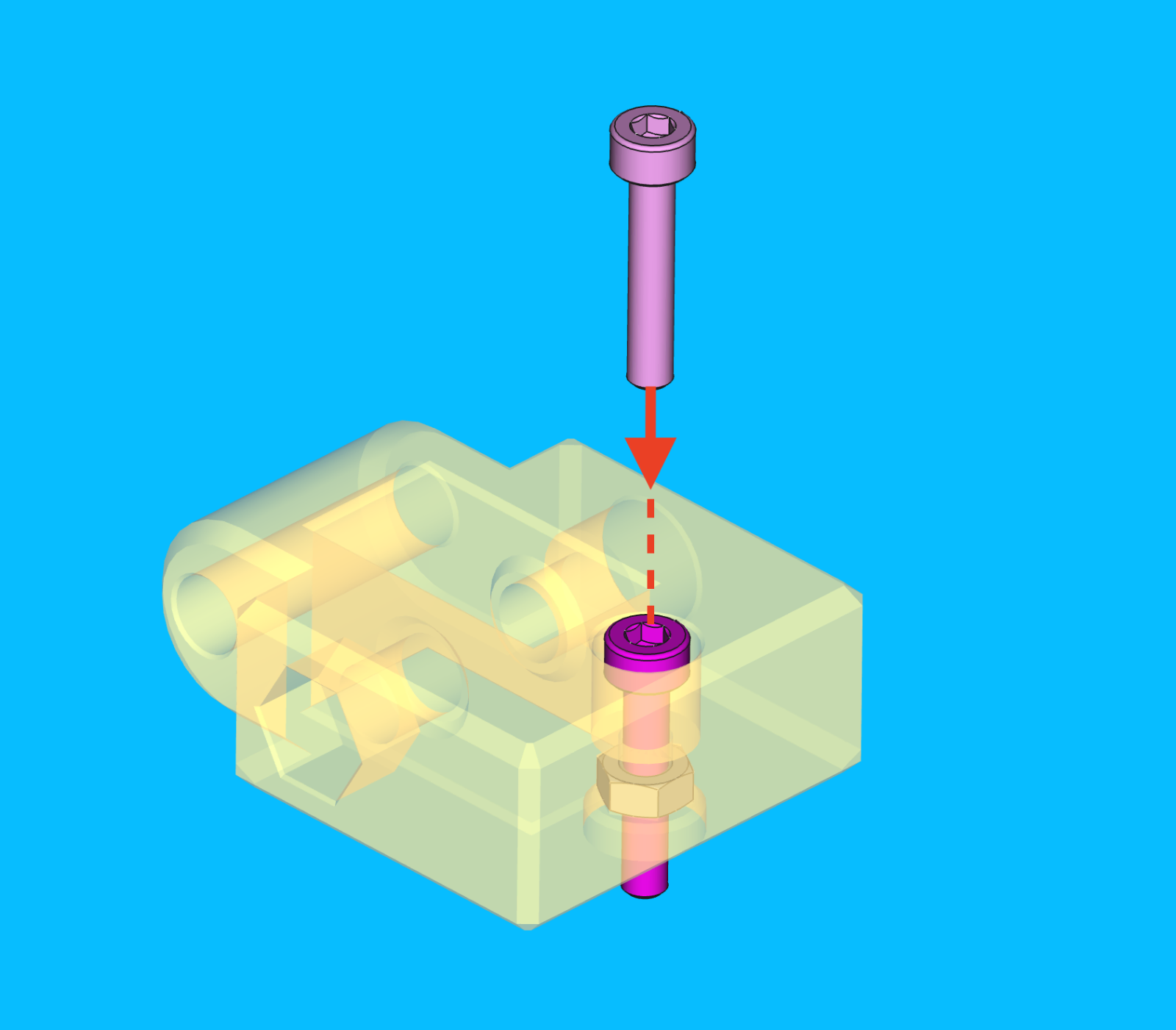
-
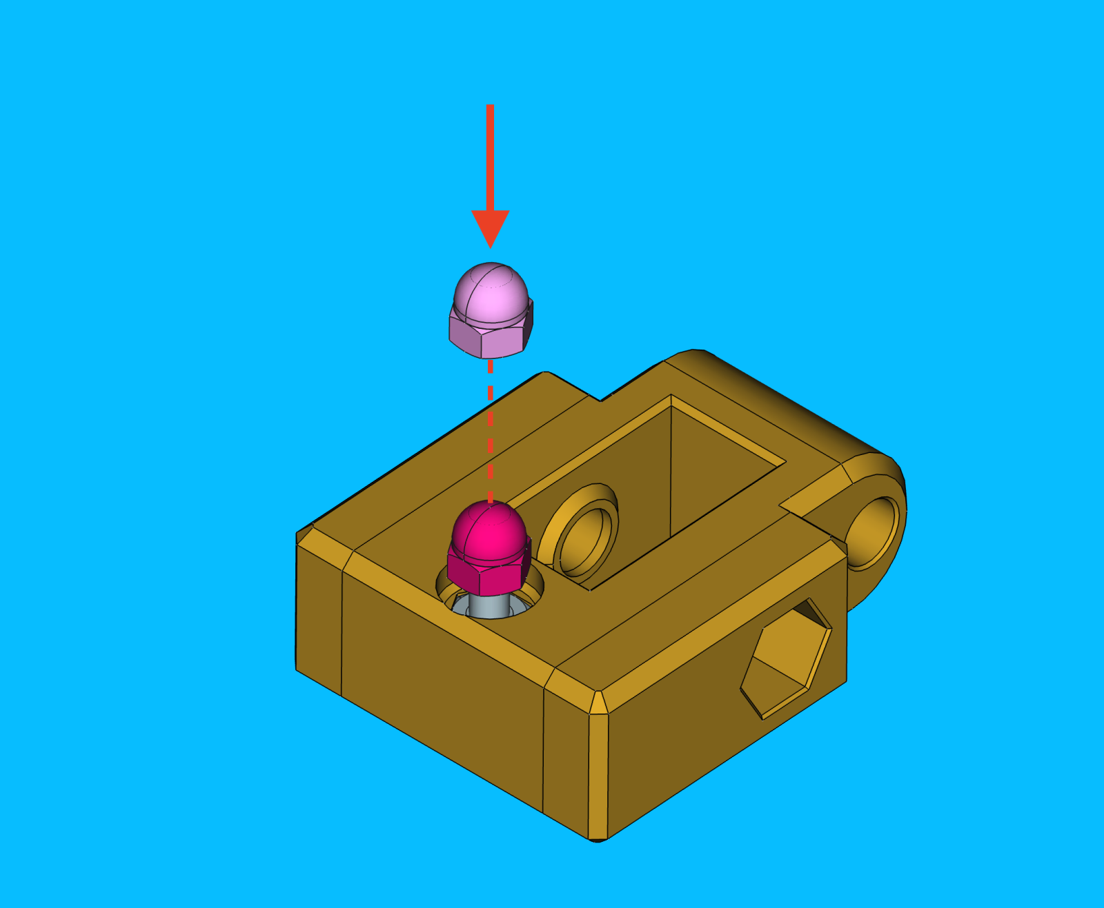
Thread a
M3-acorn-nutonto the end of the bolt- The
M3-acorn-nutandM3-hex-nutshould be on the same side of thebelt-tensioner-arm - Tighten the
M3-acorn-nutonto theM3x16-boltwith a 5.5mm socket and an allen wrench
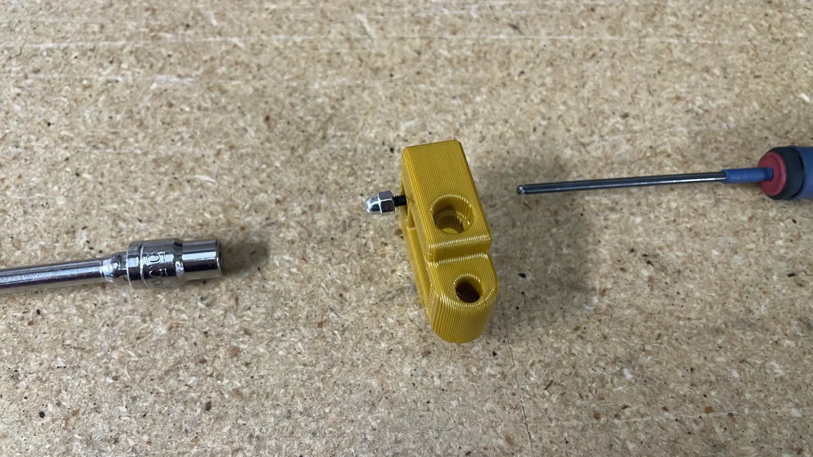
- The
-
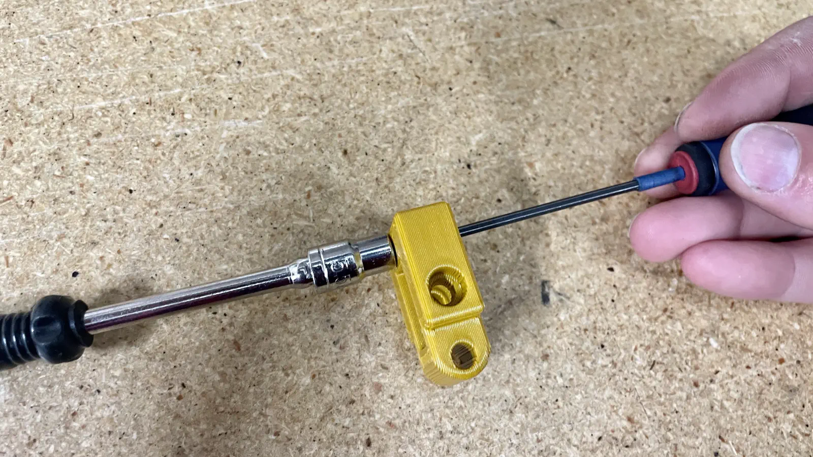
Rotate the
M3x16-boltuntil theM3-acorn-nutis fully secure and theM3x16-bolthas been threaded through the hex nut.This ensures the
belt-tensioner-armis installed with it's adjustment range fully available for when it's time to tensionGT2-belt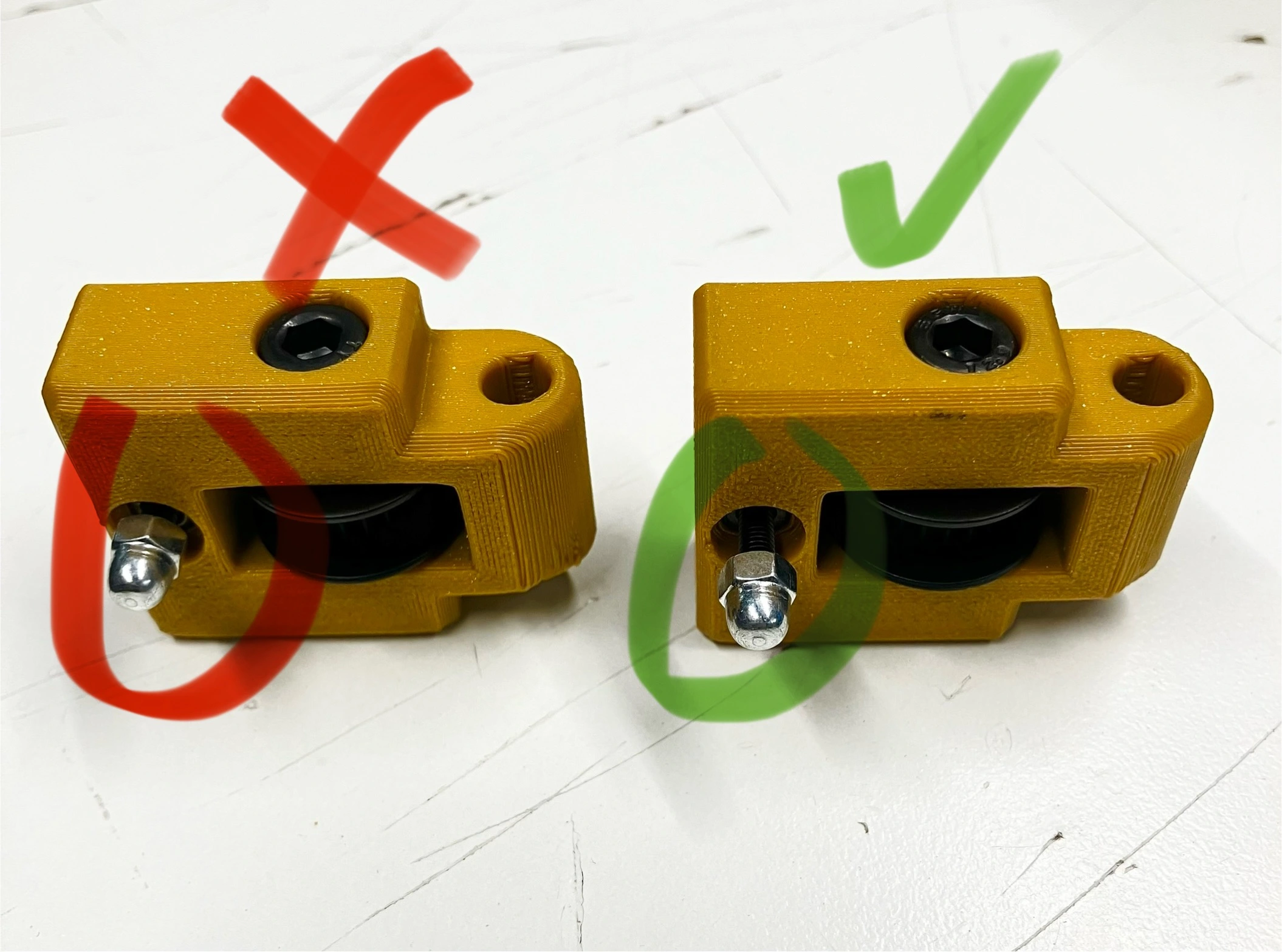
-
Insert a
M5-nylock-hex-nutintobelt-tension-arm's hex-nut pocket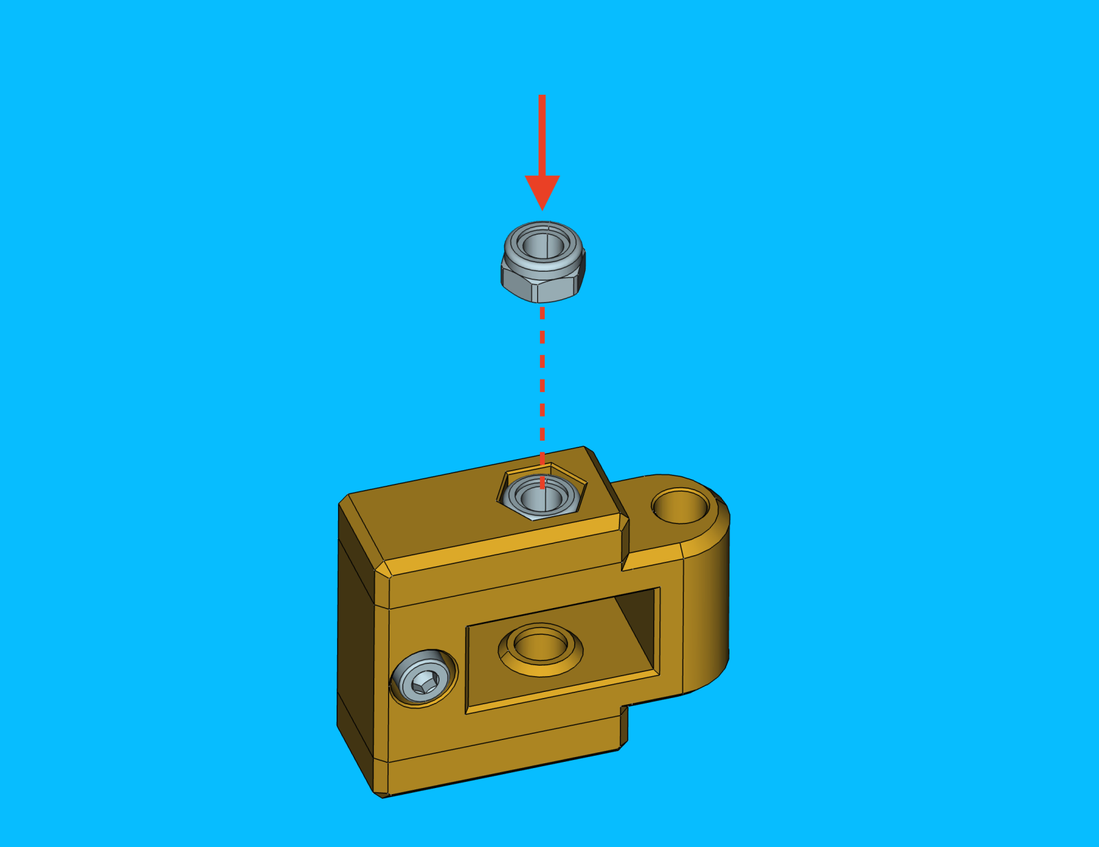
-
Slide a
GT2-idler-pulleyinto thebelt-tensioner-arm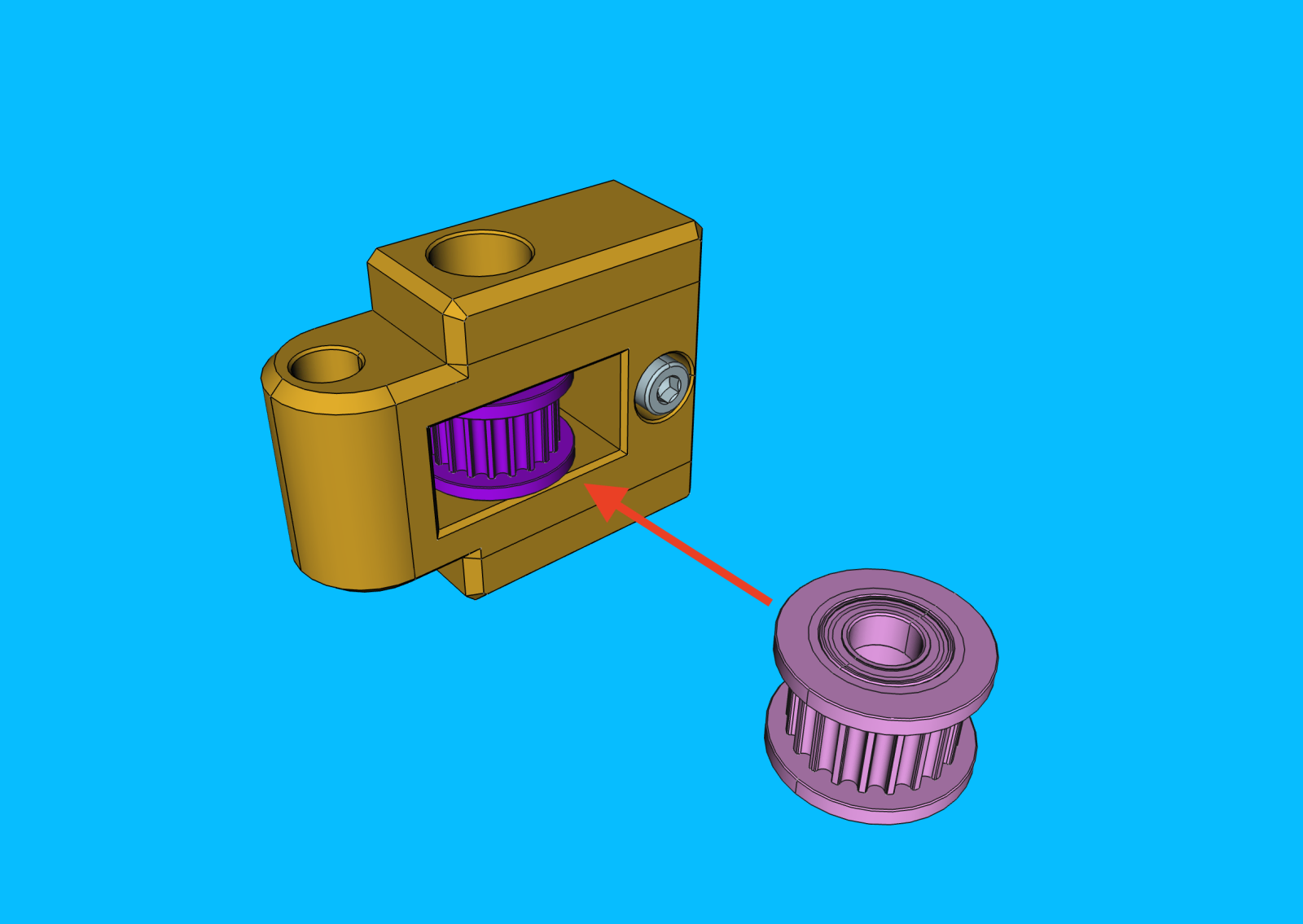
Note that the
GT2-idler-pulleyis symmetrical, so it's orientation does not matter -
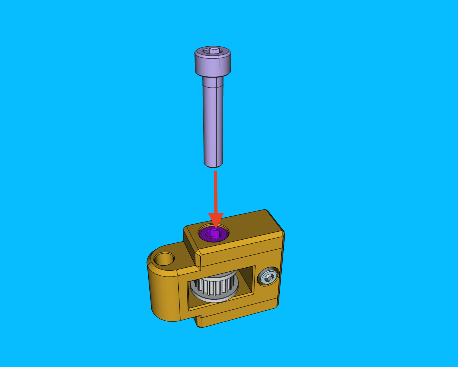
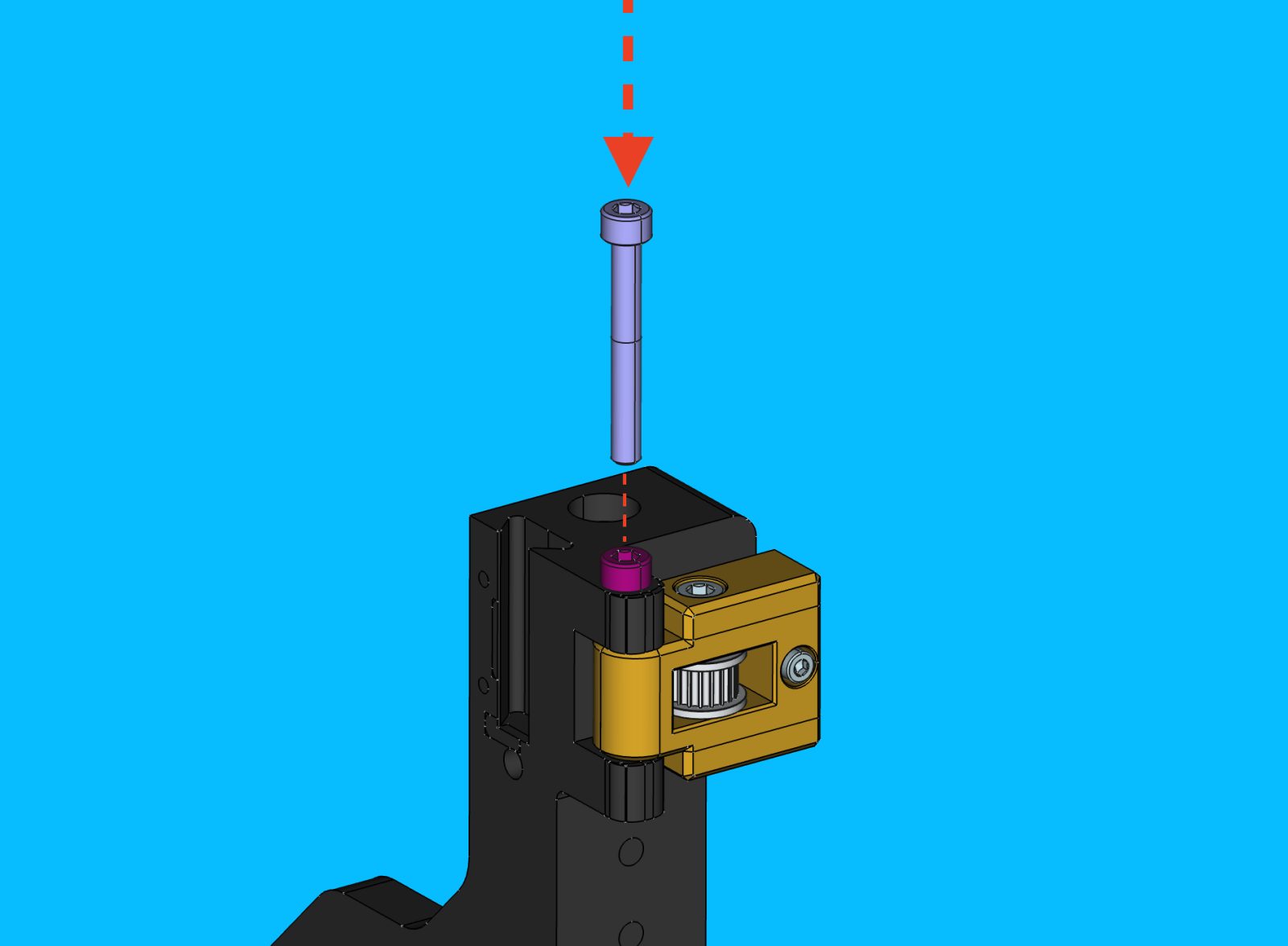
Install a
M5x25-boltinto thebelt-tensioner-armto secure theGT2-idler-pulleyin place- Avoid over tightening this bolt as the
GT2-idler-pulleyshould be able to spin freely without resistance - The bolt should, however, be tightened enough to eliminate lateral pulley movement within the
belt-tensioner-arm
- Avoid over tightening this bolt as the
Install belt-tensioner-arm onto front-left-leg
-
Add a drop of
ptfe-silicone-lubricantto both sides ofbelt-tensioner-arm's pivot point -
Install
belt-tensioner-armontofront-left-leg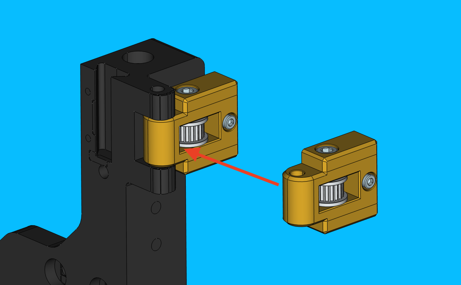
-
Secure the
belt-tensioner-armontofront-left-legwith aM5x40-bolt- Avoid over tightening this bolt as the
belt-tensioner-armshould be able to pivot freely without much resistance
- Avoid over tightening this bolt as the
-
The completed
front-left-legshould match the image shown below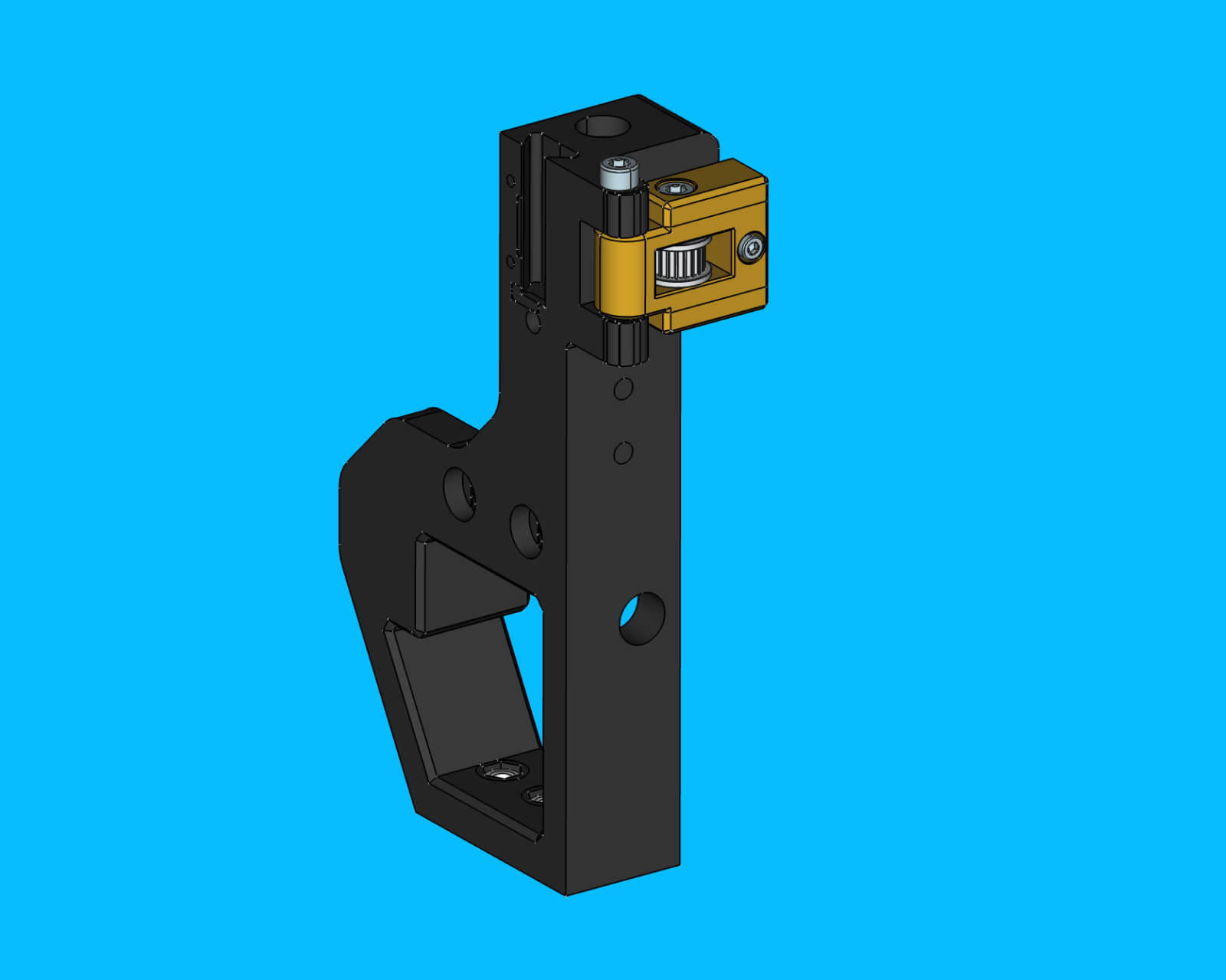
Create Back-Left-Leg Subassembly
Prepare back-leg
- Remove any stringing from the 3D print with a heat gun
- Insert an
m5-hex-nutinto the bottom of theback-leg3D print- Finger strength should be sufficient to install this fastener into position
Glue if needed
Add a drop of loctite to the region if the fastener fit is looser than normal and seems at risk of falling out in transit
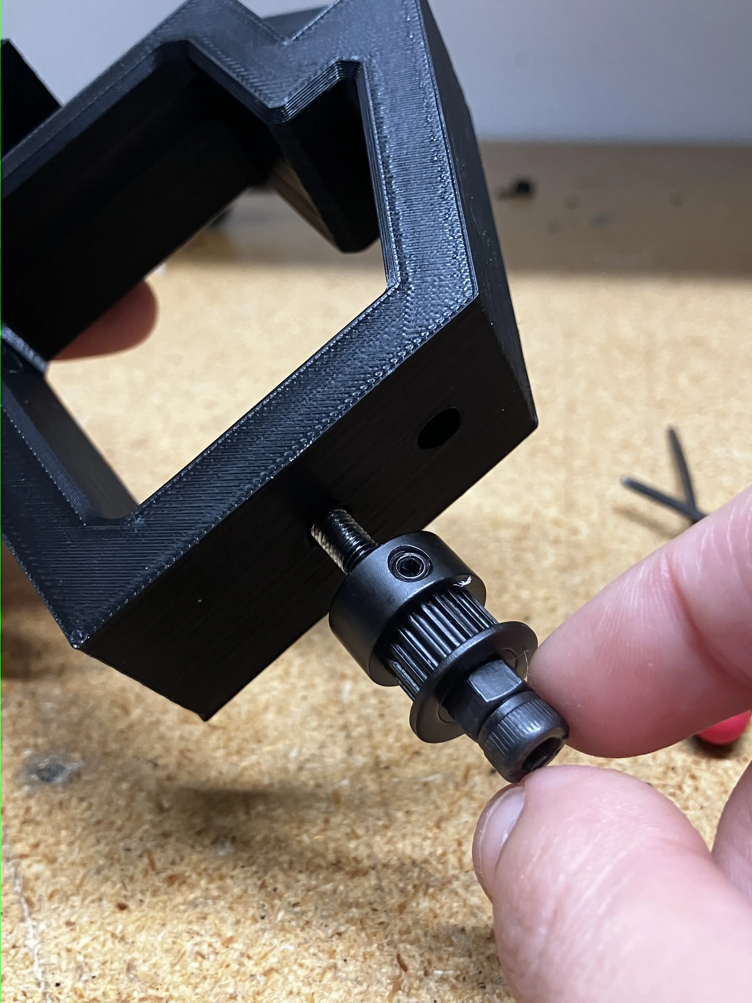
Prepare y-gantry stepper motor
-
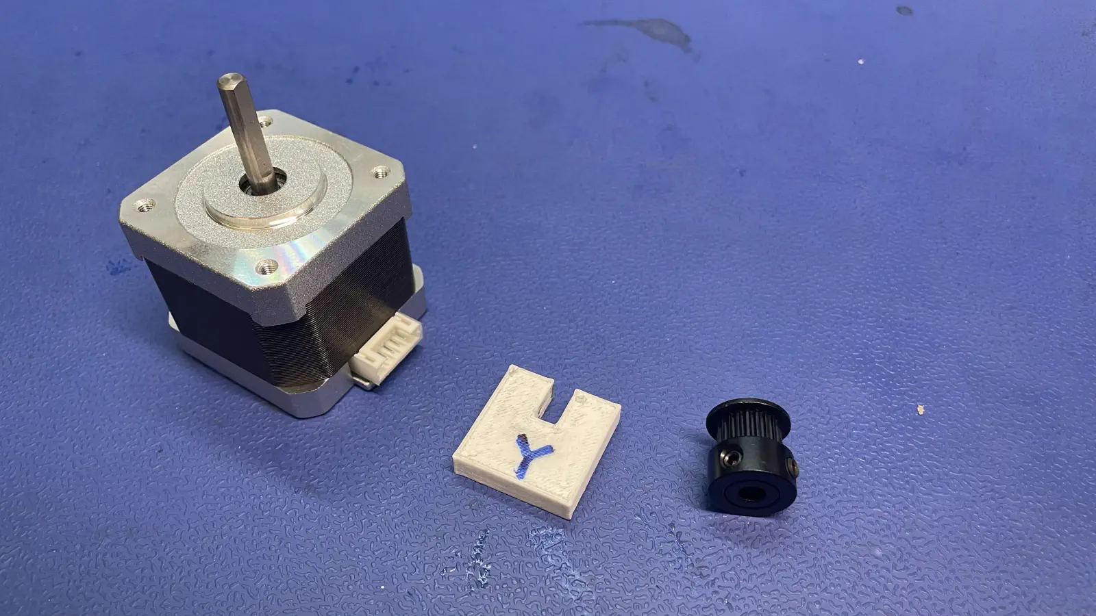
Gather the following parts and tools
- nema17-stepper-motor
- GT2-timing-pulley
- y-timing-pulley-spacer-jig
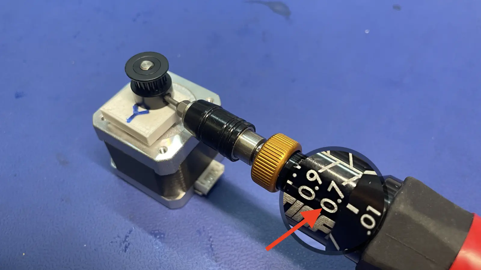
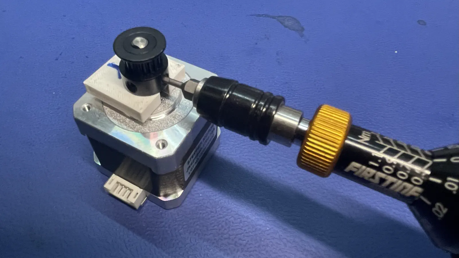
- Torque driver w/2mm hex driver, set to
0.7 N/M(not shown)
 - Use motor spacing jig to mount the timing pulley to the NEMA 17, ensuring the set screw is aligned to the flat side of the motor shaft
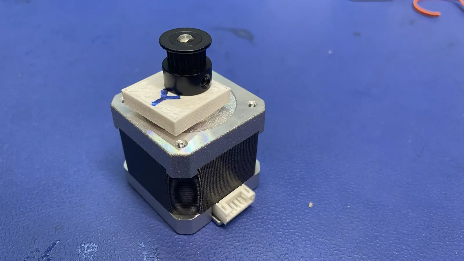 - Tighten the 2x timing pulley set screws to 0.7 N/M - first tightening the one facing the flat on the motor shaft
Install y-gantry stepper motor onto back-leg
-
Connect
Y1-stepper-motor-cableto they-gantry-stepper-motor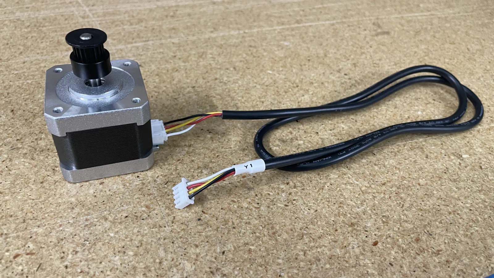
-
Install the
y-gantry-stepper-motorontoback-leg- The
Y1-stepper-motor-cableshould be routed throughback-legto exit towards the center of the machine - Ensure no wires are being crushed or strained
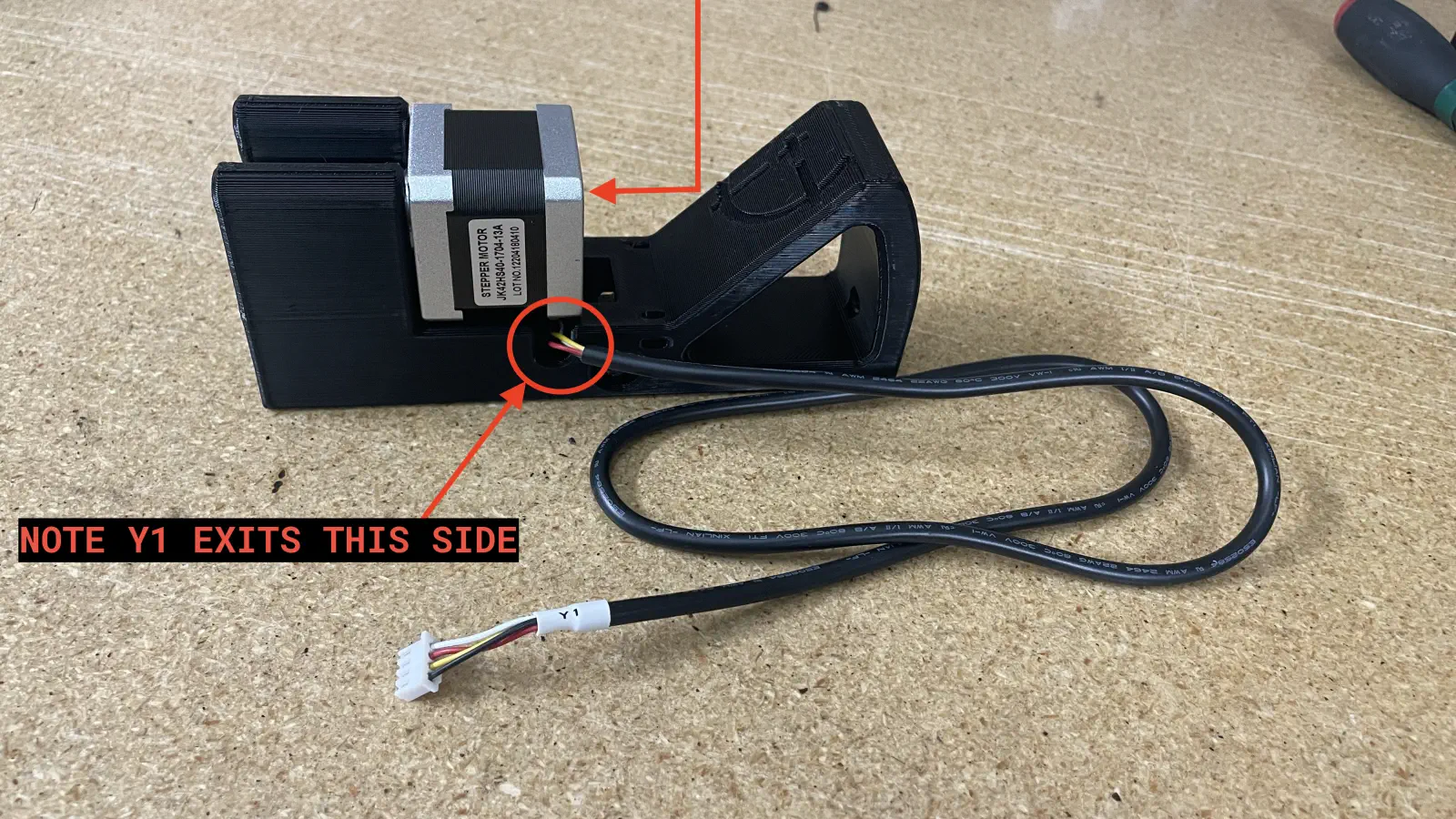
- The
-
Put 4x
M3x8-boltthrough the motor mounting holes found onback-leg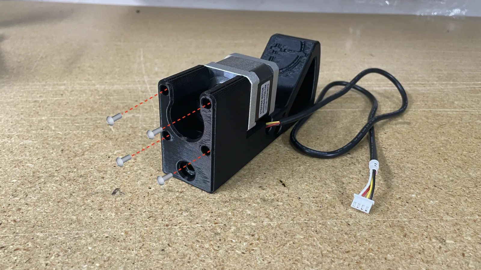
-
Install a
zip-tiefor cable strain relief-
Use a
zip-tieto attached theY1-stepper-motor-cableto theback-legto add strain relief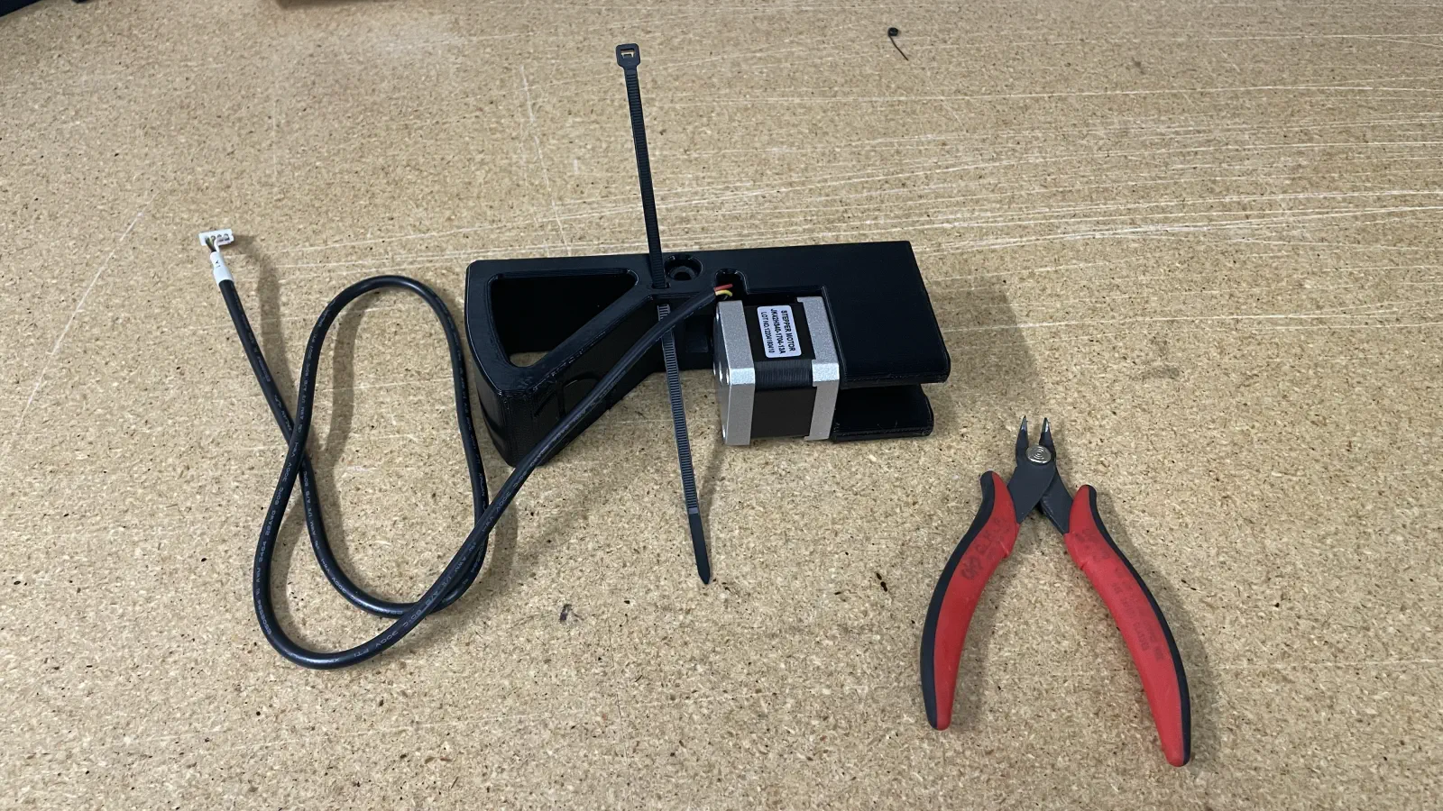
-
Cut the
zip-tiewithflush-cutters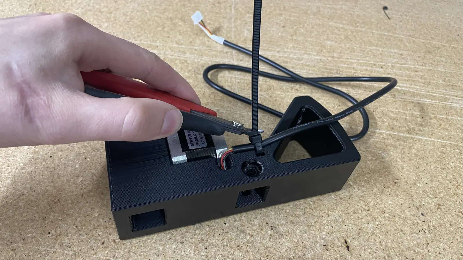
-
Ensure that
Y1-stepper-motor-cableandzip-tieare resting against the logo-face side ofback-leg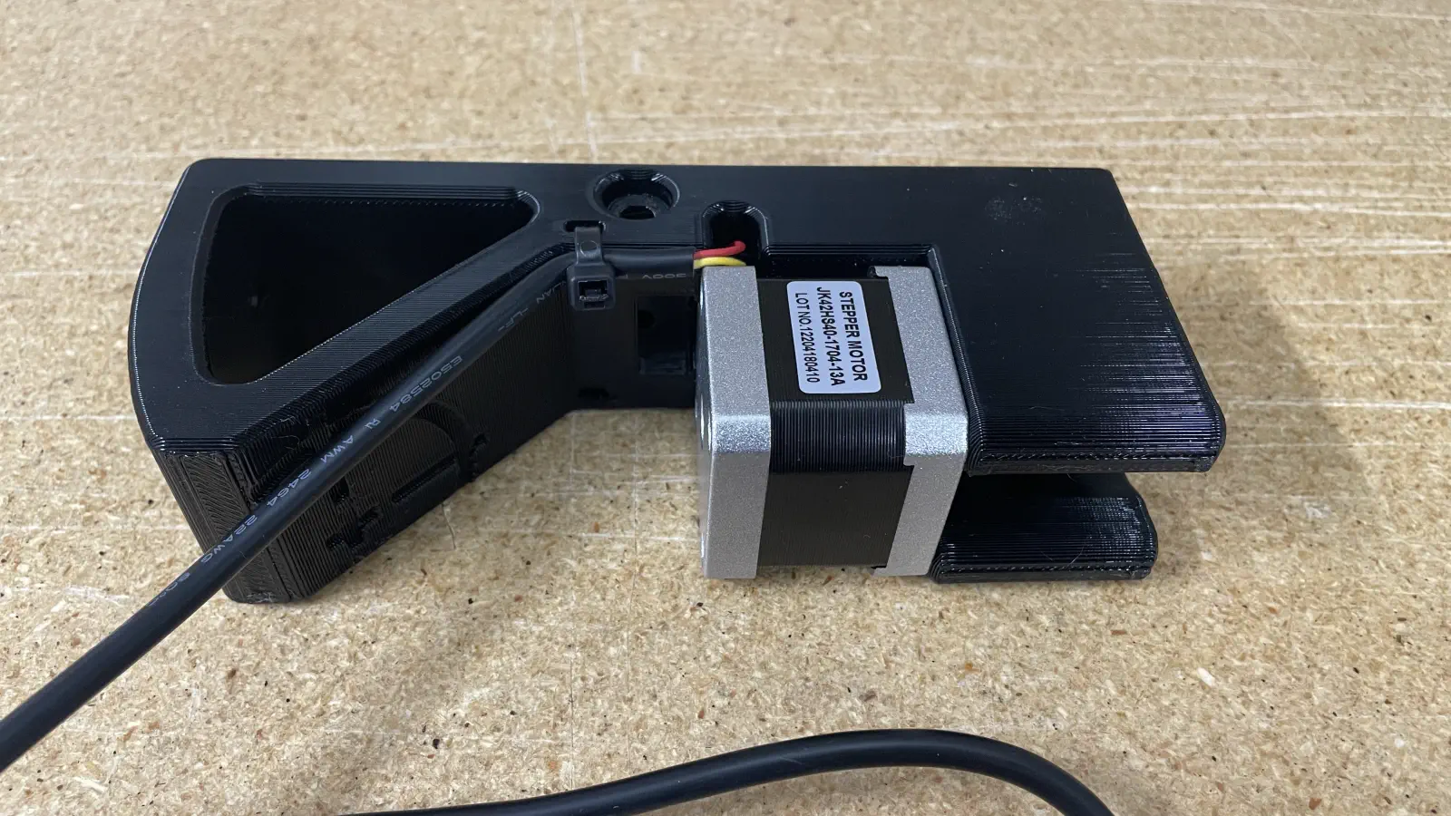
-
Assemble y-gantry-left
Install front-left-leg and back-leg onto alu-extrusion
-
Begin by inserting a
525mm-m3-t-nut-barinto a piece ofalu-extrusion- There should be about 51.5mm between the end of the
525mm-m3-t-nut-barand the right-side end of thealu-extrusionafter installation - The
525mm-m3-t-nut-barneeds to be slide aside in later steps, so do not bother to make this perfect right now
- There should be about 51.5mm between the end of the
-
Insert
front-left-legandback-legonto 2x pieces ofalu-extrusion- The
525mm-m3-t-nut-baris oriented in the top-side groove of the uppermostalu-extrusion - The extrusion pieces should be fully inserted into each leg
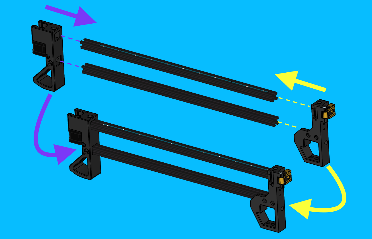
- The
-
Bolt
back-legtoalu-extrusion-
Insert 3x
m3-t-nutinto thealu-extrusionpieces before sliding each of them into alignment with the matching bolt holes onback-leg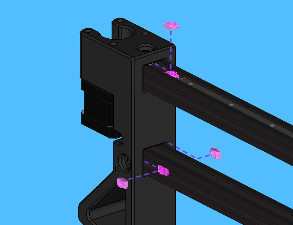
-
Insert 3x
M5x10-boltintoback-legand thread the bolts into each correspondingM5-t-nut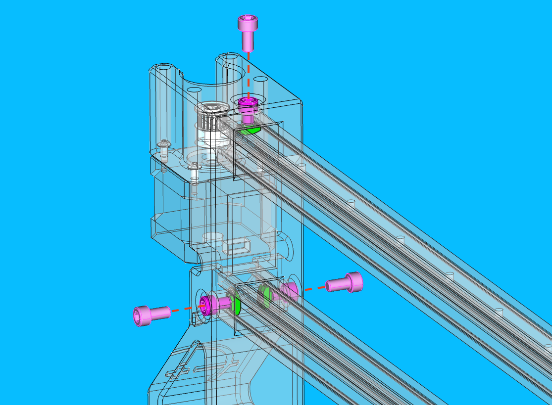
-
-
Bolt
front-left-legtoalu-extrusion- Slide the
M3-t-nut-barout of the way if needed - Insert an
M5-t-nutinto the upper channel ofalu-extrusion -
Align the
M5-t-nutwith the top-side bolt hole onfront-left-leg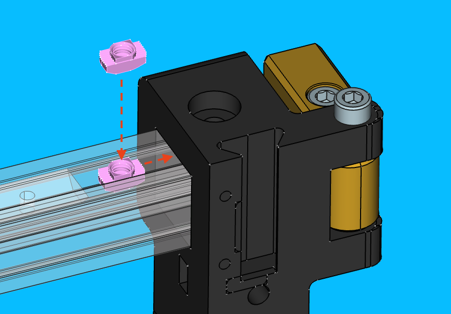
-
Insert a
M5x10-boltinto the top-side bolt hole onfront-left-legand tighten it into theM5-t-nut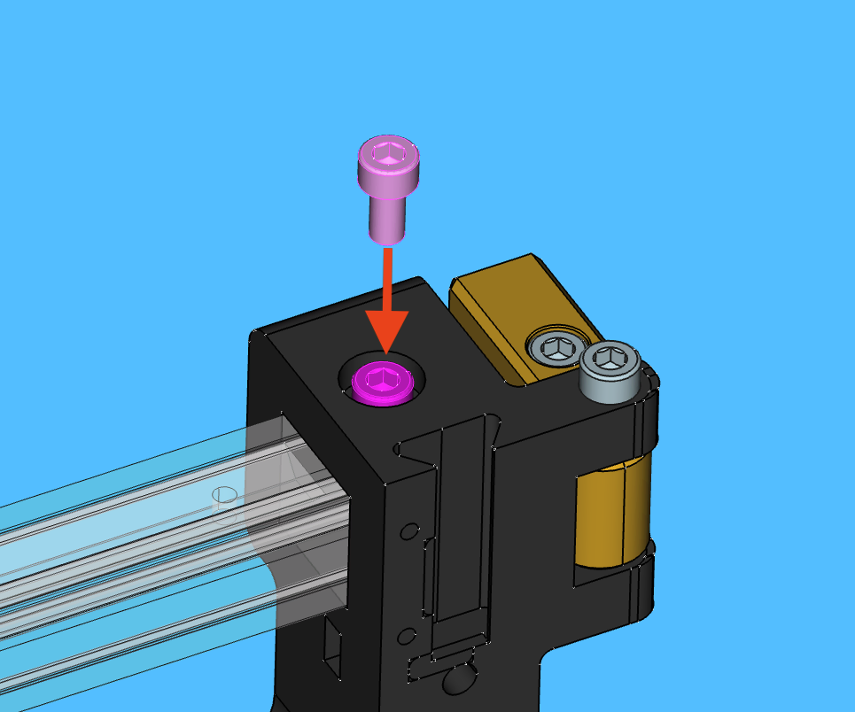
-
Slide 2x
M5-t-nutinto the the side channel of loweralu-extrusionand align them with the two bolt holes onfront-left-leg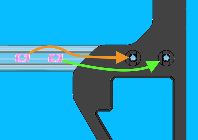
-
Insert 2x
M5x10-boltinto the side bolt holes onfront-left-legand tighten each into the correspondingM5-t-nut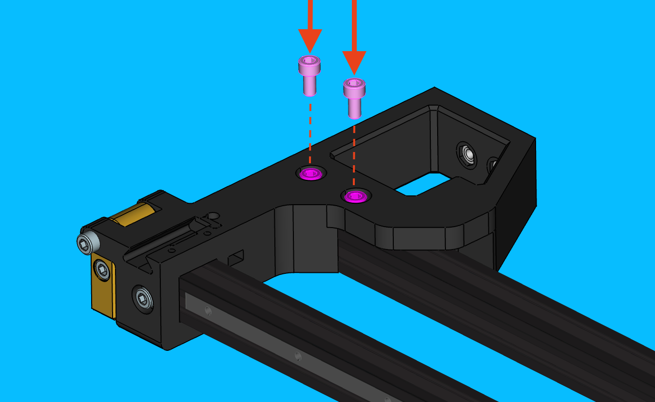
- Slide the
-
Compare the WIP
y-gantry-leftassembly to the image below after completing all previous steps, address any discrepancies as needed before proceeding onward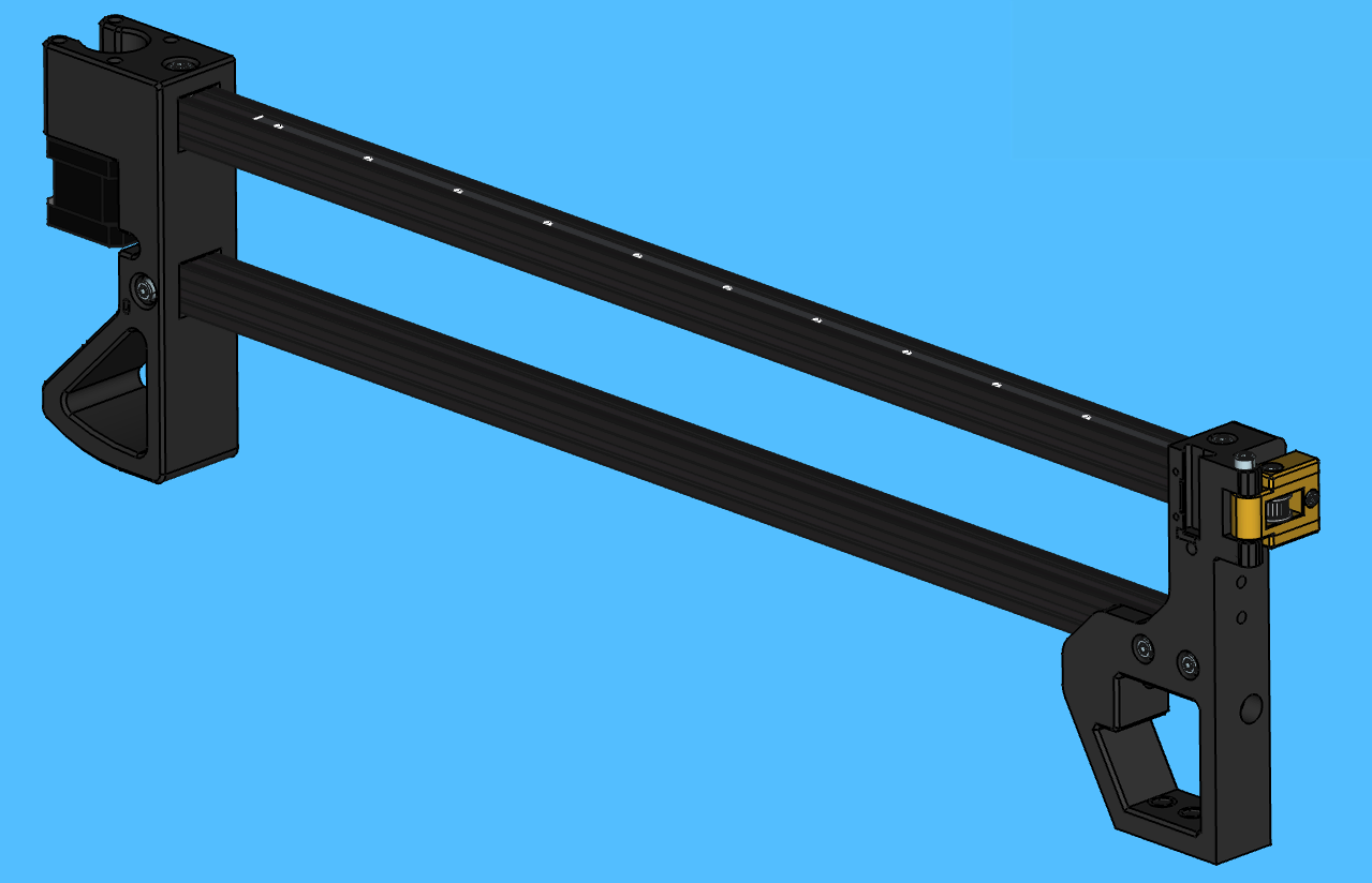
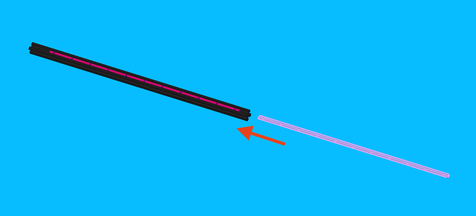
Install linear-rail-550mm
-
Roughtly position
linear-rail-550mmonto top-side of uppermostalu-extrusion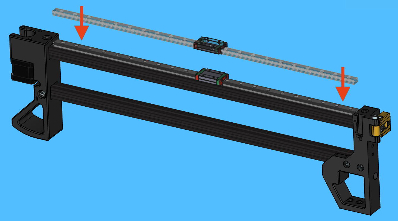
-
Place a
linear-rail-2020-alignment-jigon both ends oflinear-rail-550mm- Do not cover any bolt holes with the jig
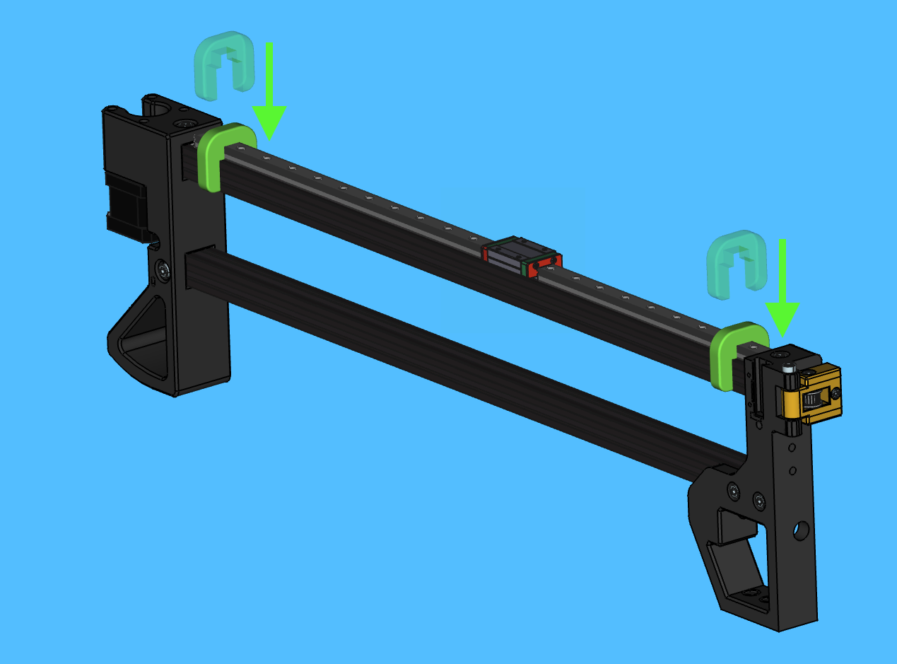
-
Visually center the
linear-rail-550mmbetween theback-legandfront-left-leg - Slide the
M3-t-nut-barto line up with the linear rail's bolt hole pattern -
Starting from the
front-left-legside, lightly snug aM3x8-boltinto every other bolt hole onlinear-rail-550mm- Move the
linear-rail-carriageout of the way as needed
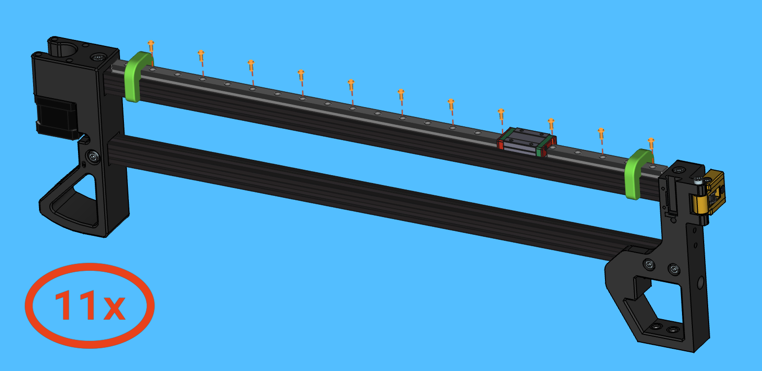
- Move the
-
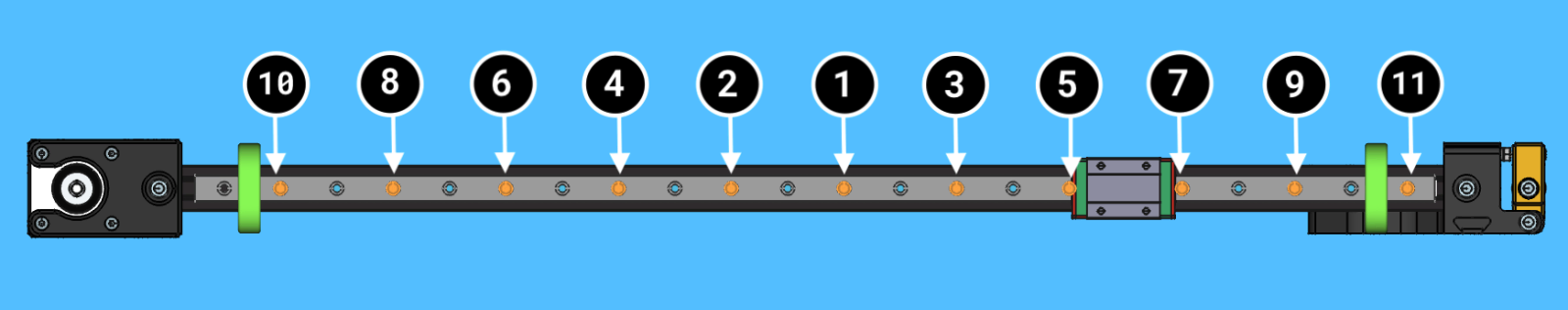
Torque the rail mounting bolts to specification in sequence beginning with the bolts at the center of the rail and working towards each end
- A torque wrench should be used to set the specified bolt torque
- The torque specification for these
M3x8-boltsis0.5N/M
-
Remove the
linear-rail-2020-alignment-jigfrom both ends oflinear-rail-550mm - Slide the linear-rail-carriage back and forth a few times, checking to see that it travels smoothly and consistently
Halfway Checkpoint
-
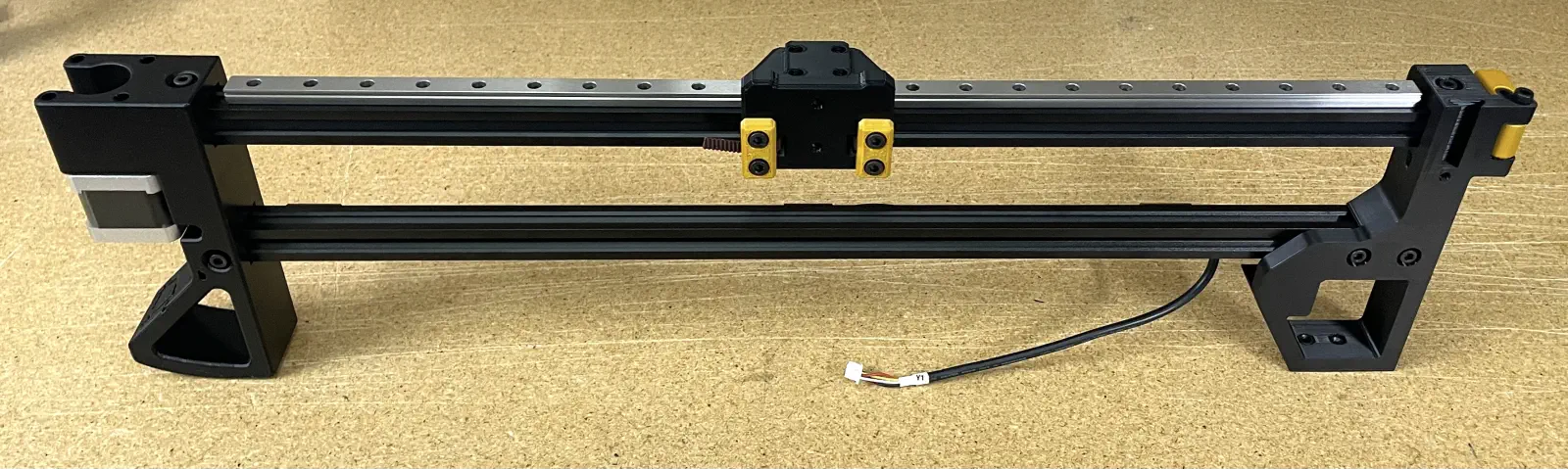
Verify that
y-gantry-leftmatches the following photo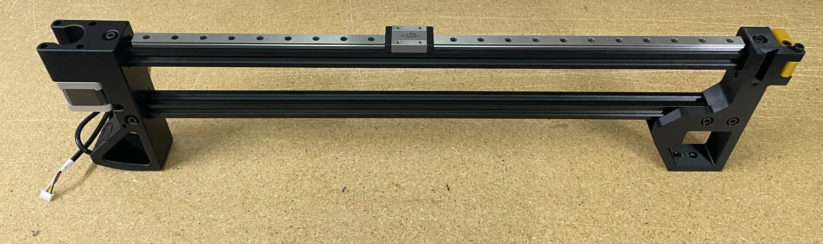
If y-gantry-left matches the photo, proceed to the next section
If y-gantry-left does not match the photo, correct discrepancies before proceeding to the next section
Install GT2-belt
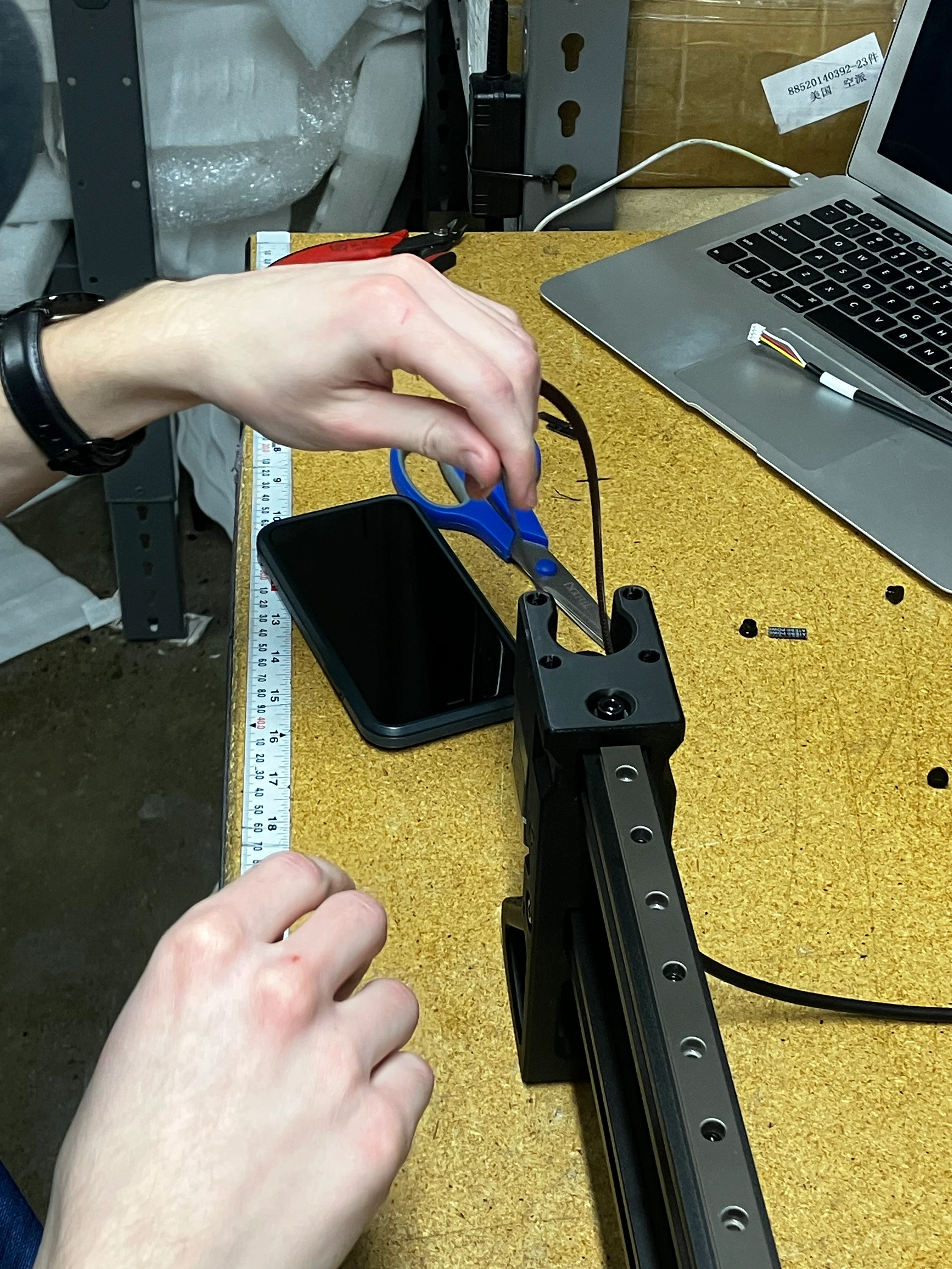
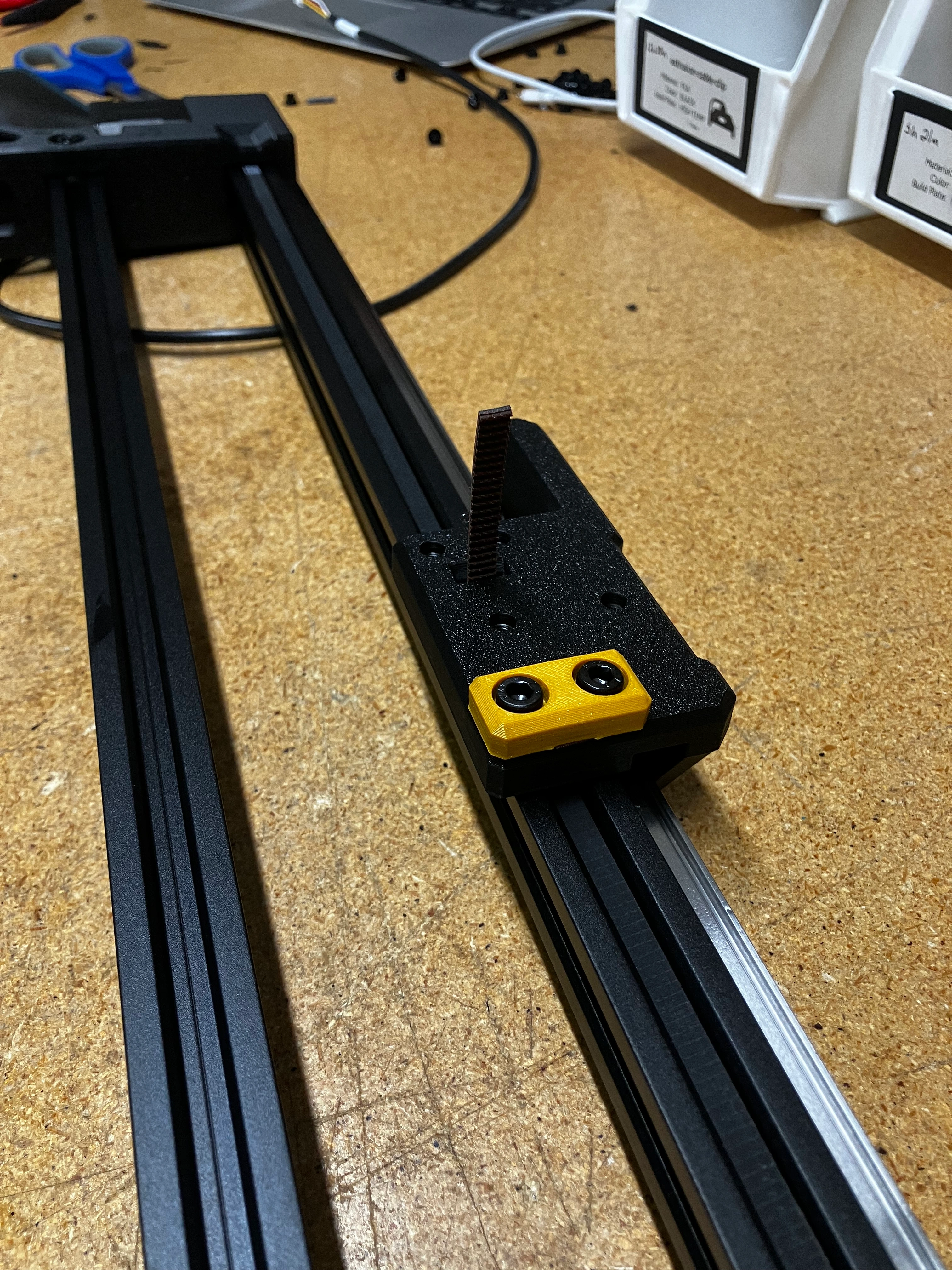
- First slip
GT2-beltthroughy-gantryitself. -
Work it through the end that is closer to the
belt-tension-arm. (The side that DOES NOT have the long end with the two holes on top)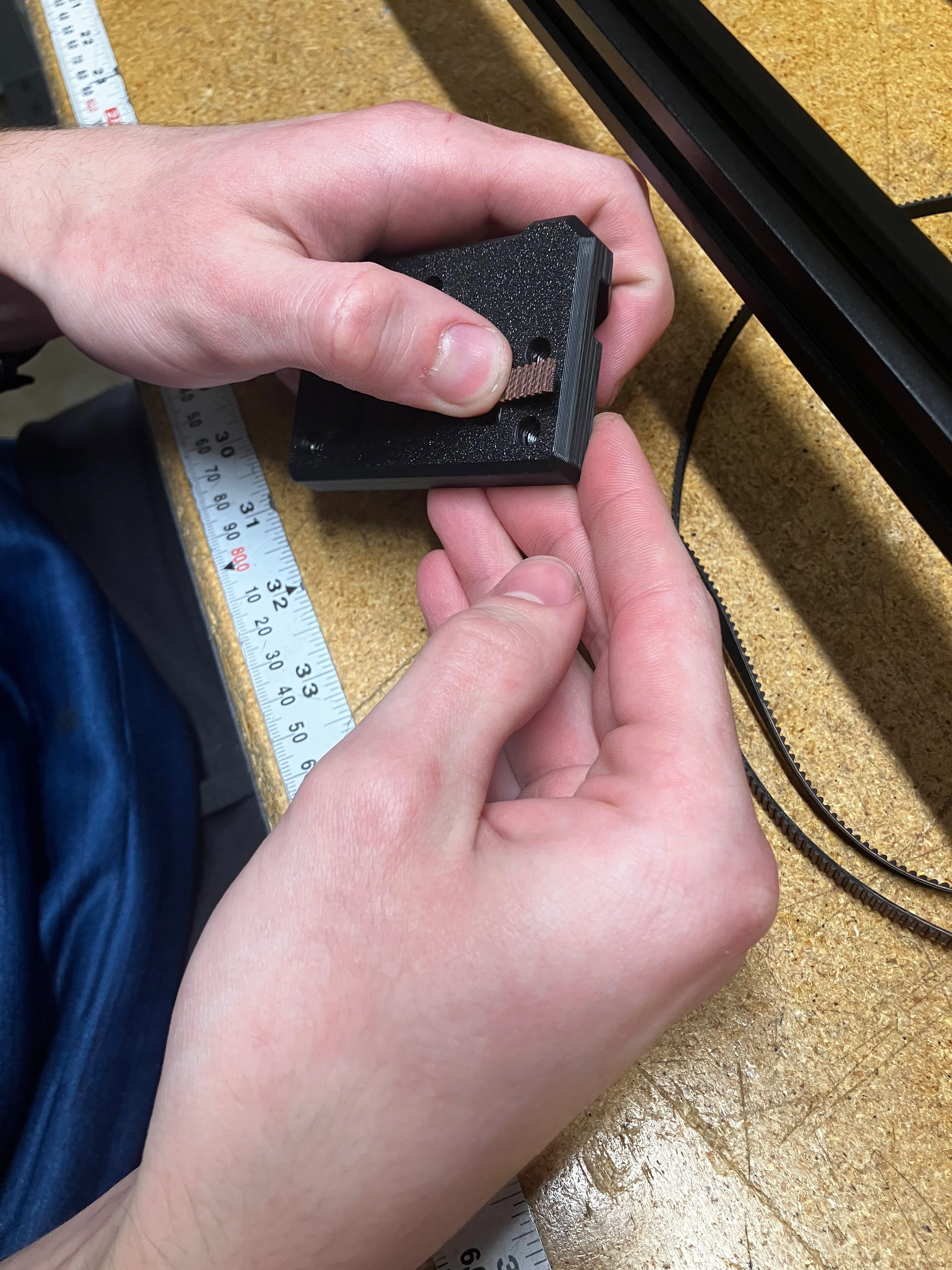
-
Grab a
belt-clamp, have theGT2-belt&belt-clampbe flushed to the edge of gantry as much as possible. Screw it down with 2xM5x10-bolt.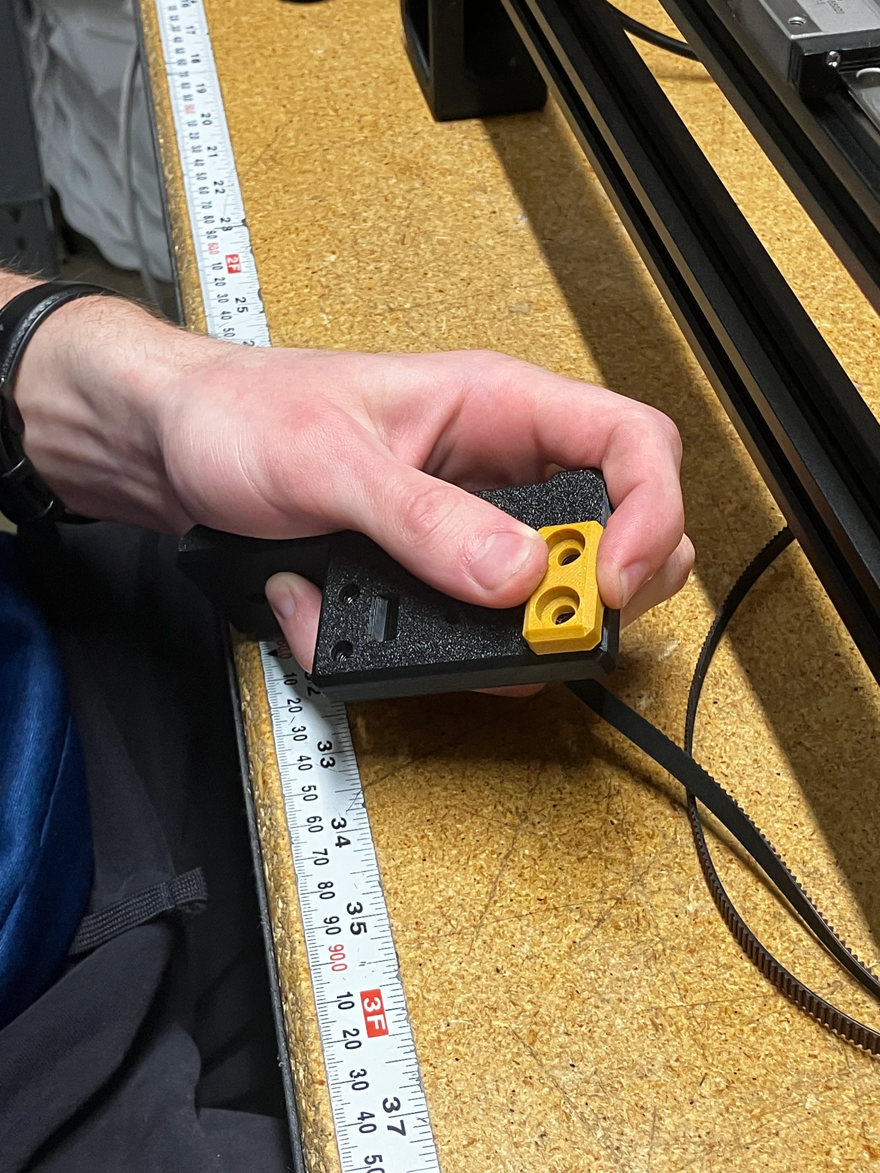
With the other end of the GT2-belt
- Snake it through the
extrusion-railon thebelt-tension-armside first. Front to back. - Wrap it around the
idler-pulleyin thebelt-tension-arm, then snake it through the back of theextrusion-rail. - Pull it all the way to the other side of the rail, into the open channel, around the
timing-pulleyon theNEMA-17. - Then bring the working end of the
GT2-beltto the gantry and snake the belt from back to front in the open section for the belt.
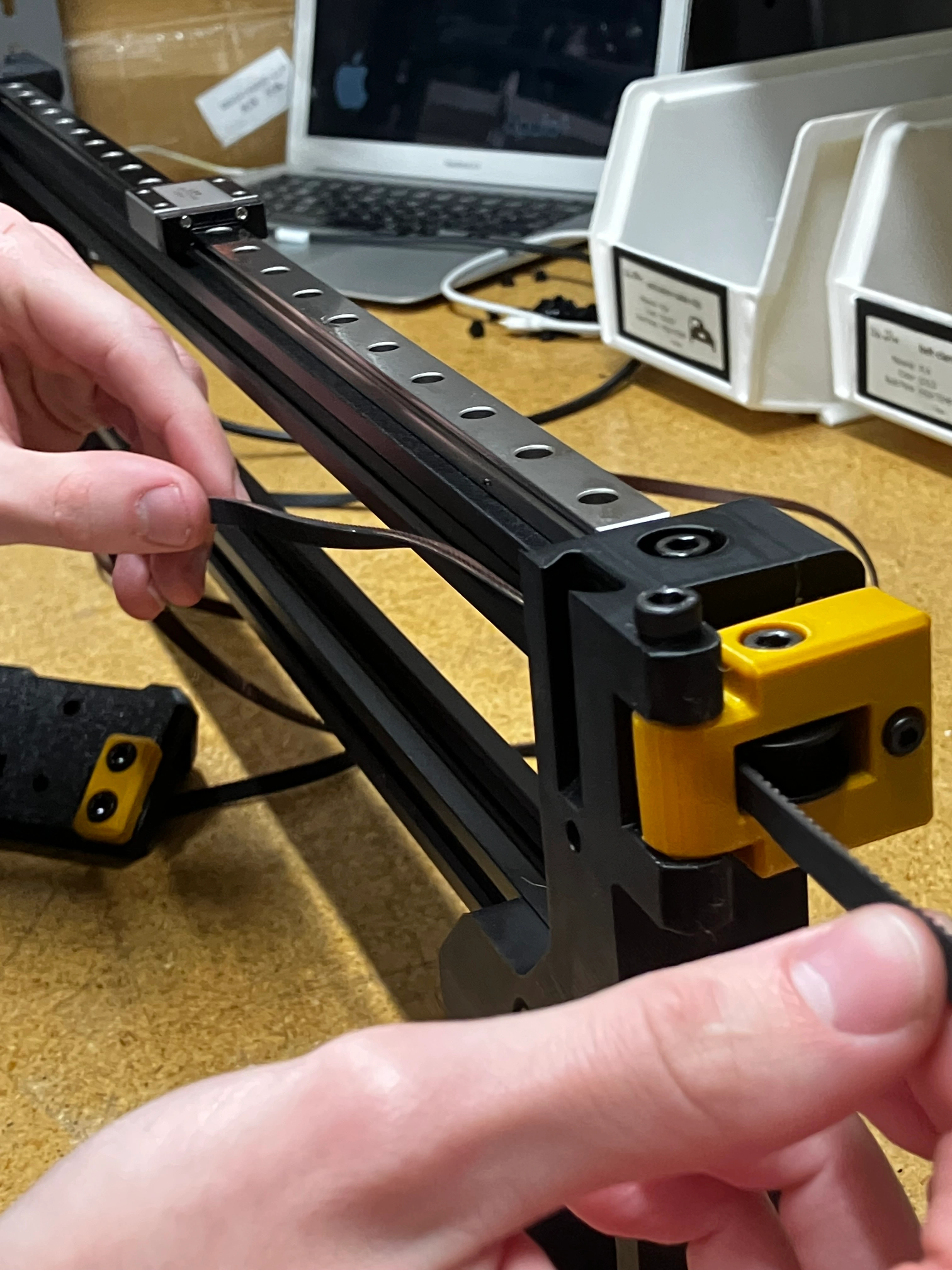
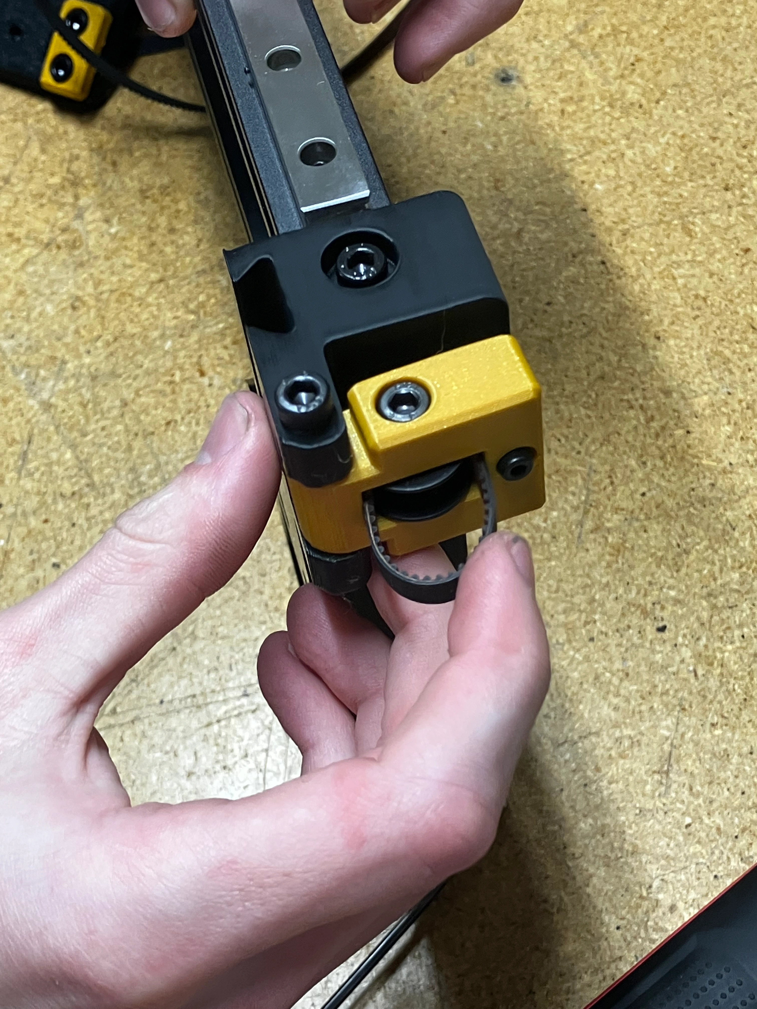
While tightening in the next step, make sure that the belt does not twist in the extrusion-rail and stays flushed on the angles on the back of the gantry.
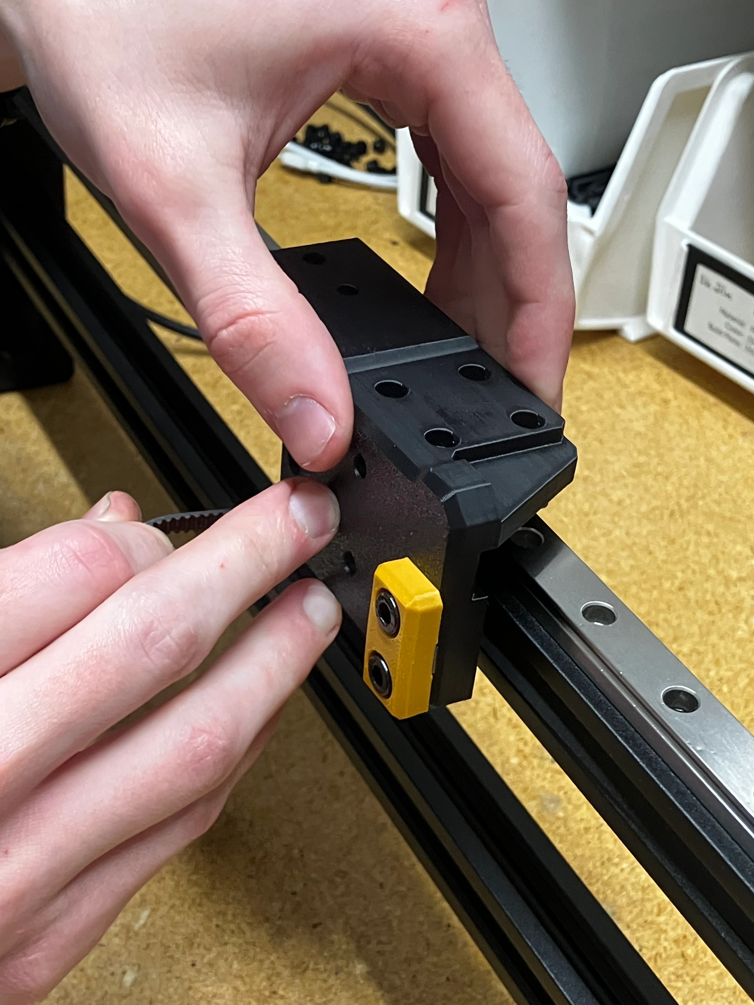
- Bolt
y-gantryto thelinear-rail-carriagewith 4xM3x8-bolt- Use threadlocker for each bolt
- Tighten each bolt to 0.7 N/M
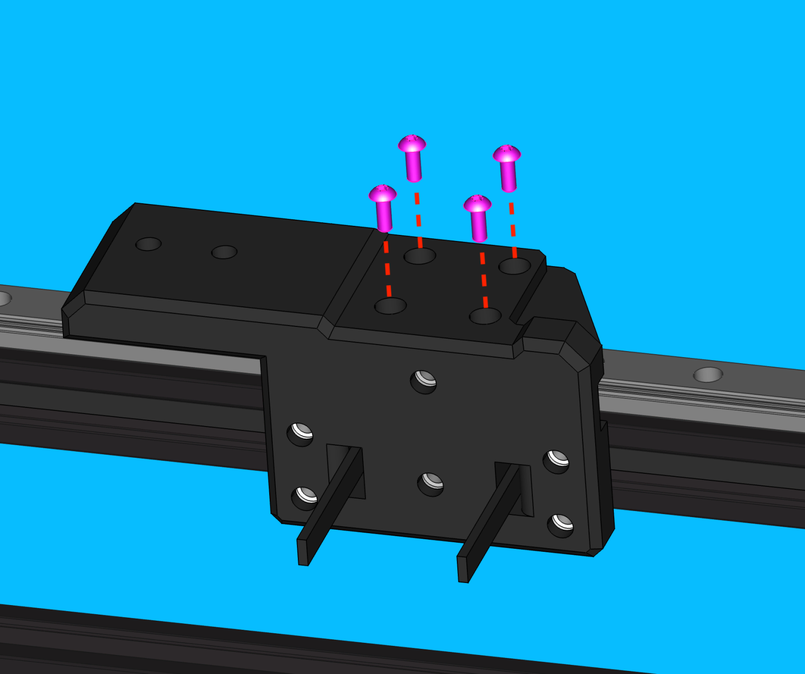
Ensure that y-gantry sits flush against linear-rail-carriage without any visible gaps
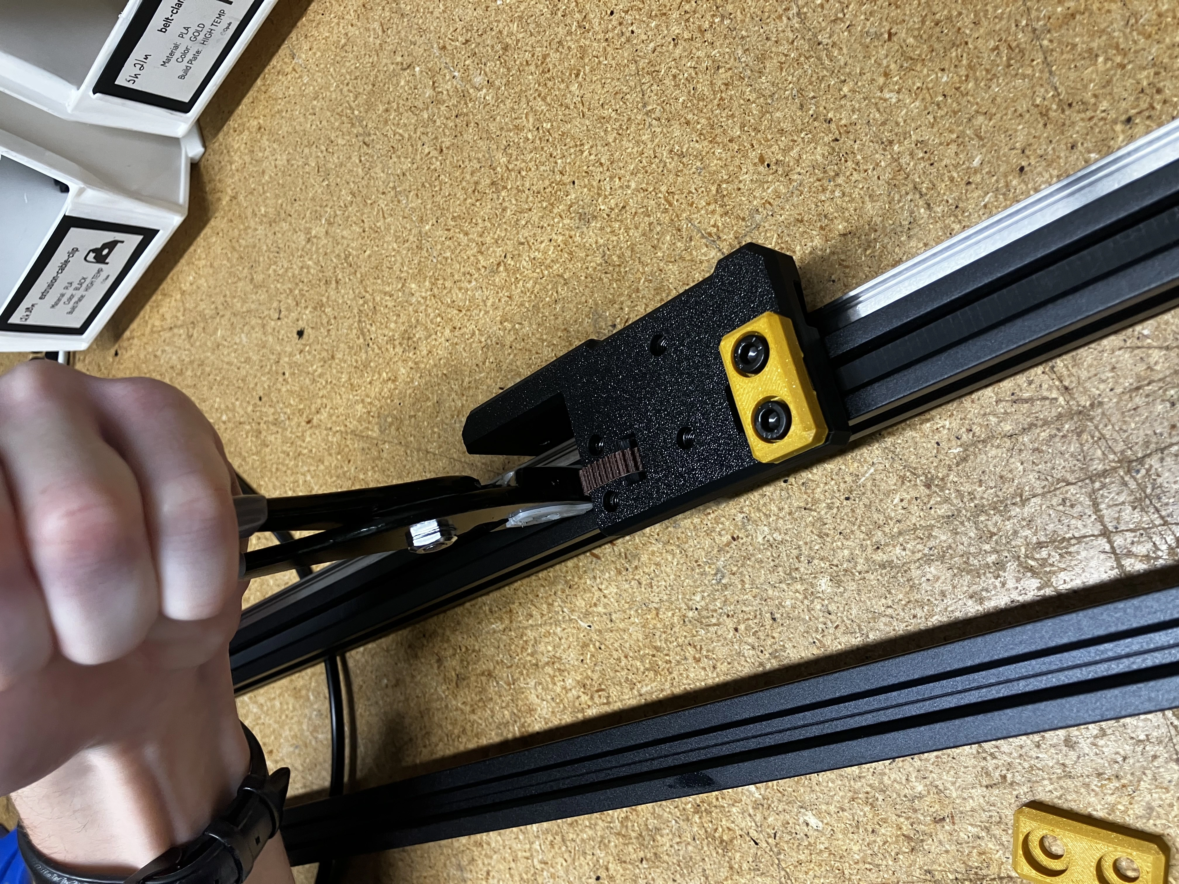
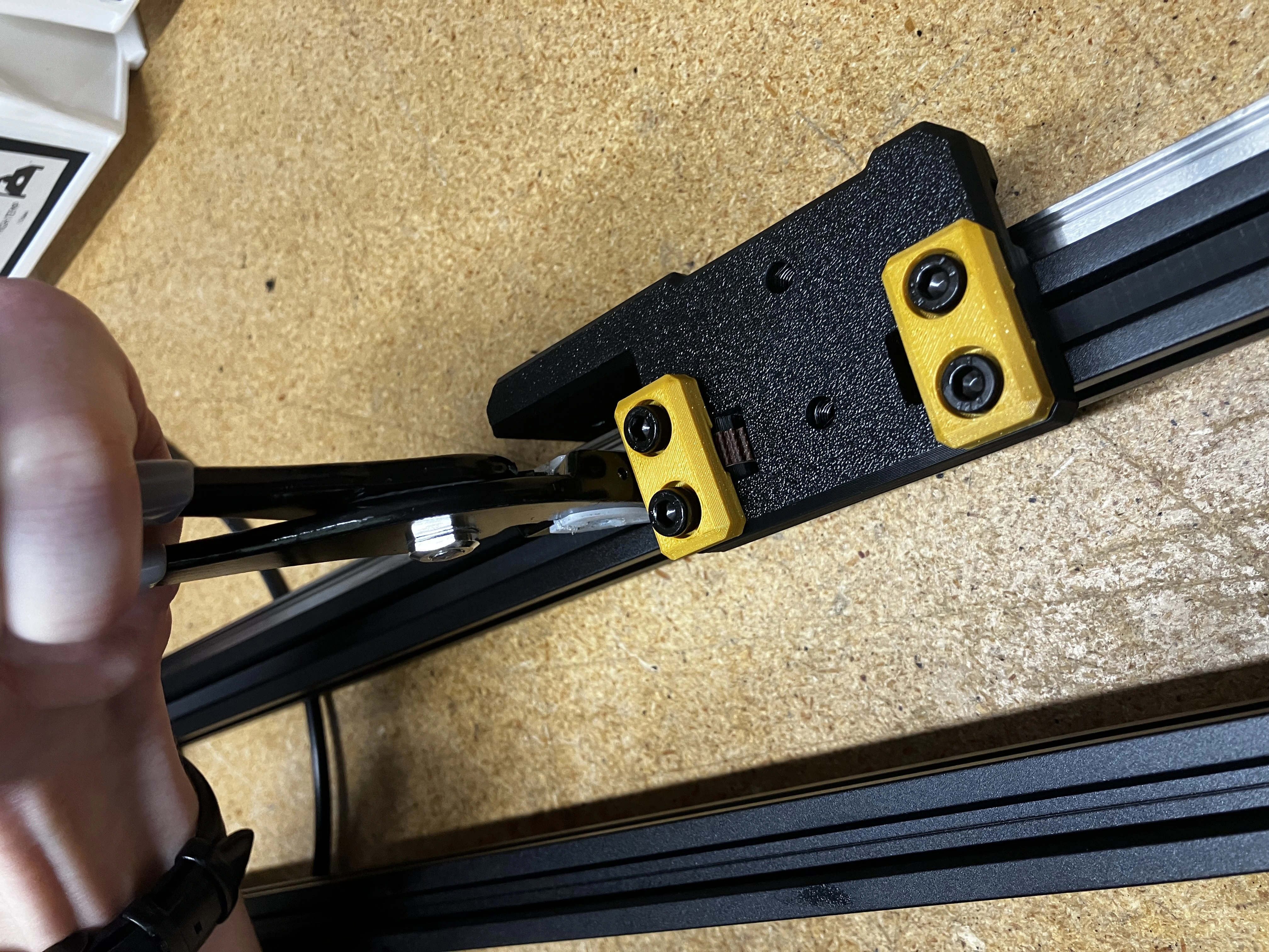
- Place the partially assembled leg on its side so the gantry face and the
GT2-beltare facing up. This will make it so much easier for tightening without the gantry moving so much.
- Either with your fingers or the soft jaw pliers, you will pull that working end of the
GT2-beltto tighten it to theextrusion-rail. Once you have tensioned it, screw it into place with abelt-clampand 2xM5x10bolts.
Add cable management
-
Use 3x
extrusion-cable-clipto secure theY1-stepper-motor-cableto the inner side of the loweralu-extrusion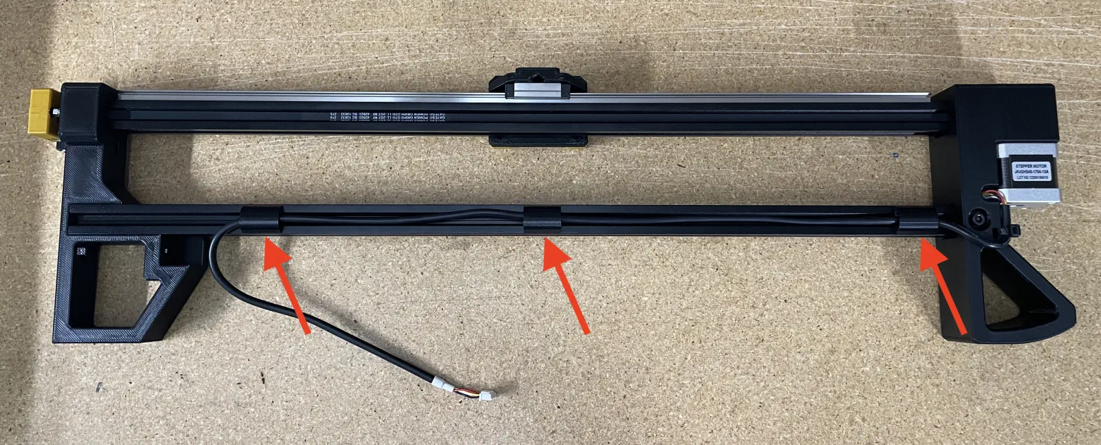
-
Position the right-most
extrusion-cable-clampand the cable to match the following image: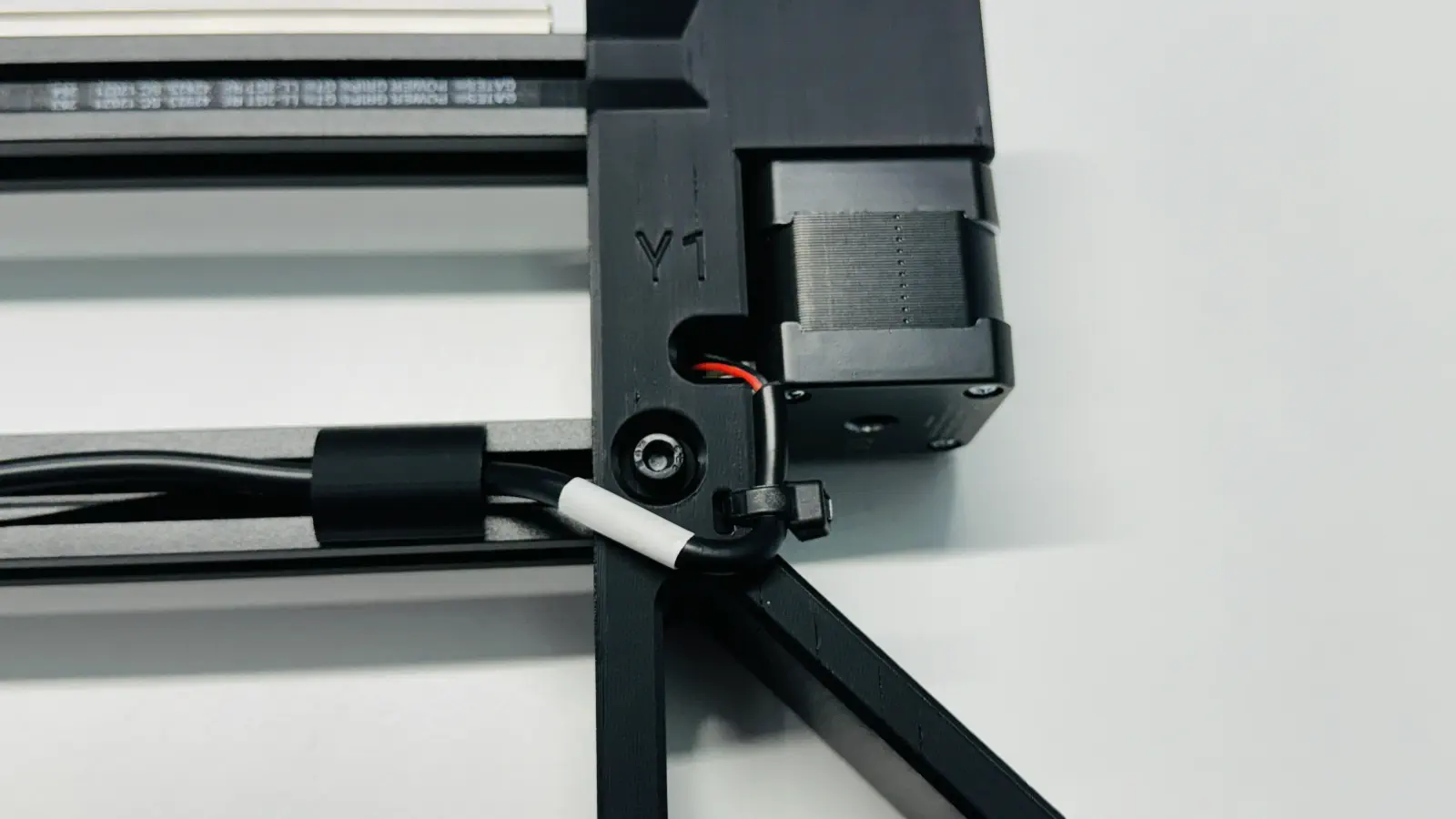
Quality Checks
A y-gantry-left that was built while following the above steps will match the following image.
Confirm this by inspecting the completed y-gantry-left assembly with the following QC checklist:
- Confirm M5 bolts are installed in every counterbored region
-
M5-hex/square-nutinstalled where required:- 2x
M5-hex-nutpressed into bottom offront-left-leg -
1x
M5-square-nutpressed into side offront-left-legfor use withy-limit-strikerThis is only applicable when building y-gantry-left
Please ignore this QC check when building y-gantry-right.
-
1x
M5-hex-nutpressed into bottom ofback-leg - 2x
M5-hex-nutpressed intoy-gantry
- 2x
-
GT2-belthas been trimmed to appropriate length:- Flush on
front-left-legside - Approx. 15mm on
back-legside
- Flush on
GT2-belthas been correctly tensionedGT2-beltlays flat in thealu-extrusionchannelstiming-pulleyis tightened down and at proper heighttensioner-armis installed onfront-left-legin the correct orientation (IE acorn-nut facing touches leg)linear-railis centered atopaluminum-extrusiony-gantry-leftsits flat onlinear-rail-carriagey-gantryfeels smooth and free of friction across the y-min to y-max travel range when actuated by hand- 3x
extrusion-cable-cliphave been installed onto the loweralu-extrusion Y1cable is secured with a zip-tie and exits the port labeledY1
Stay vigilant for new failure modes not listed above and report them to a production lead when found
If all checks pass
Set the finished y-gantry-left aside for Buddy QC testing