Peel Motor Assembly
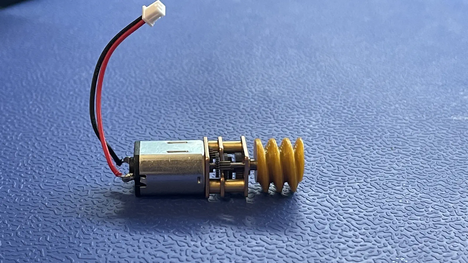
This section will guide the reader on how to properly glue the worm-gear onto the shaft of a peel-motor to create peel-motor-asm.
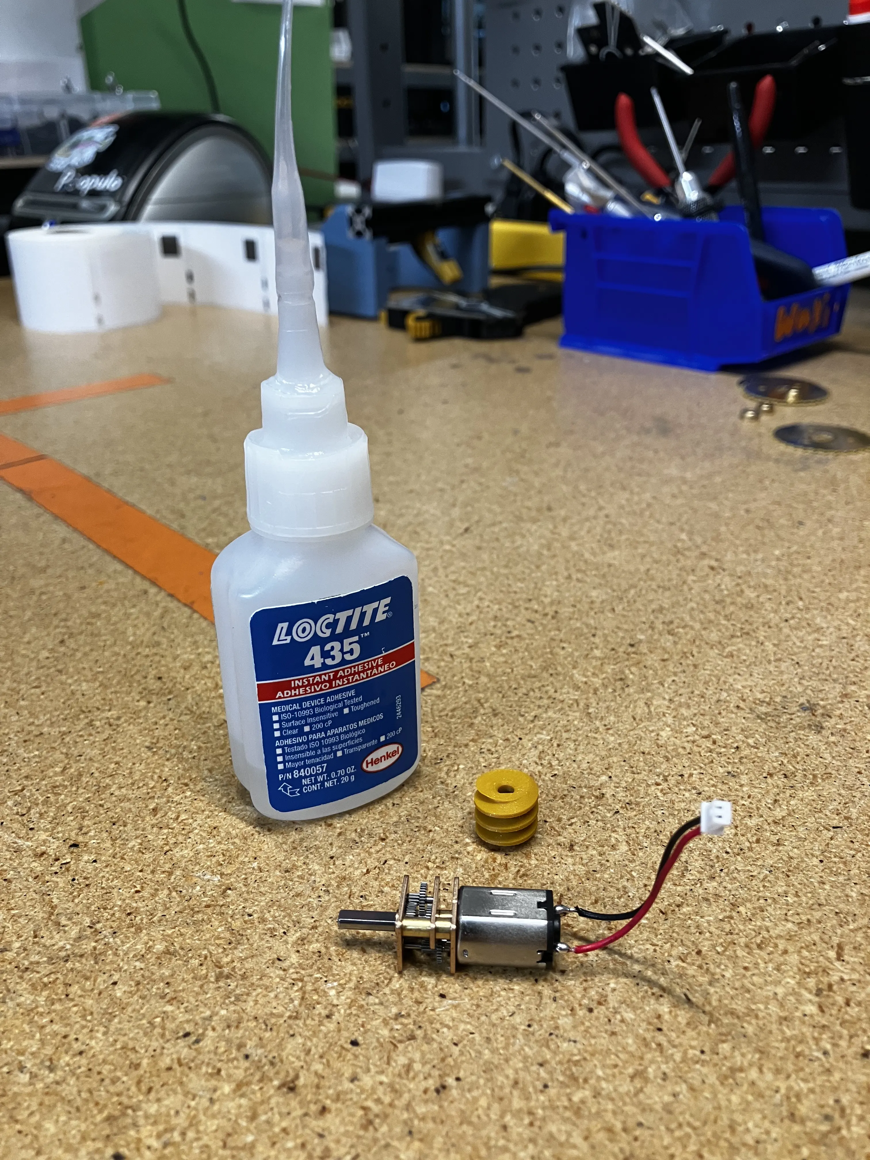
Materials
LOCTITE 435worm-gearpeel-motor
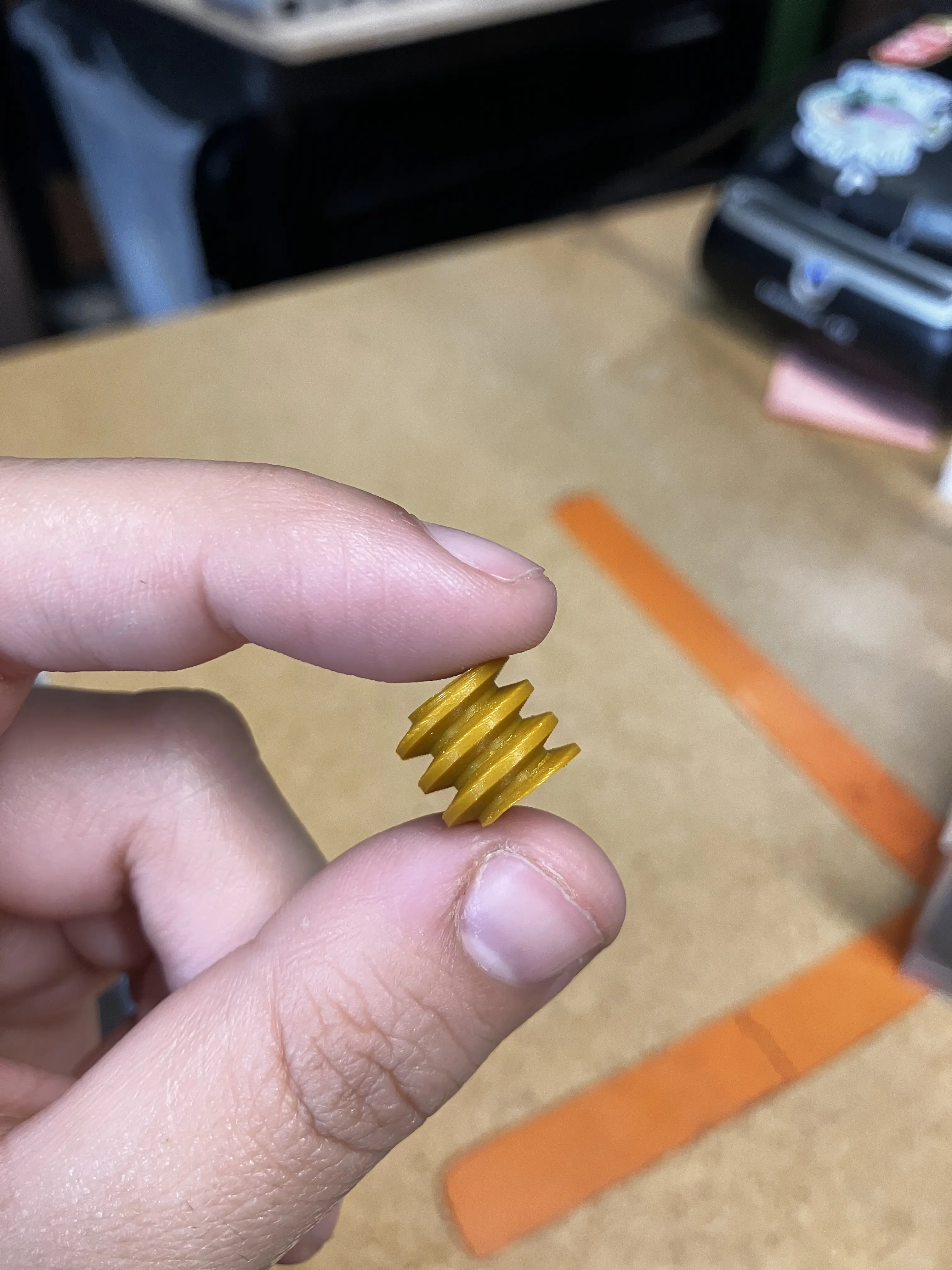
QC Worm Gears
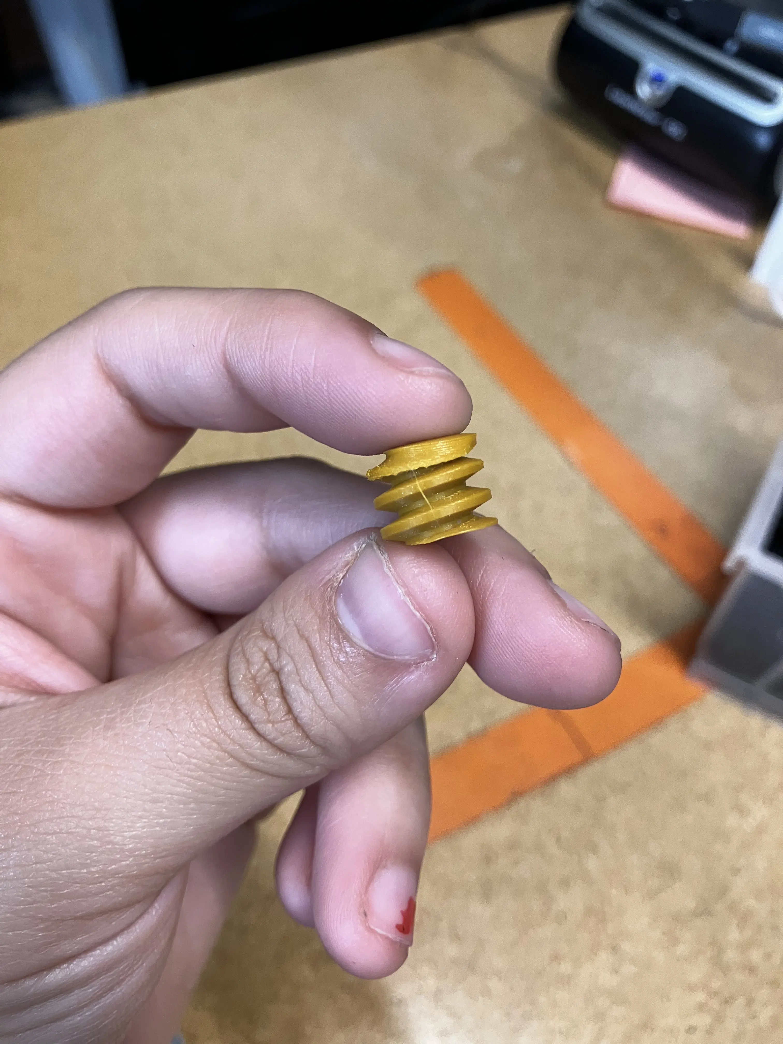
worm-gearsshould have a consistent even spiral throughout. It is to make sure that thepeel-gearteeth can move within theworm-geargrooves.
A beautiful worm-gear!
Nasty boy worm-gear!
-
run a
peel-gearmanually through the grooves of theworm-gearto confirm that in can run through without resistance.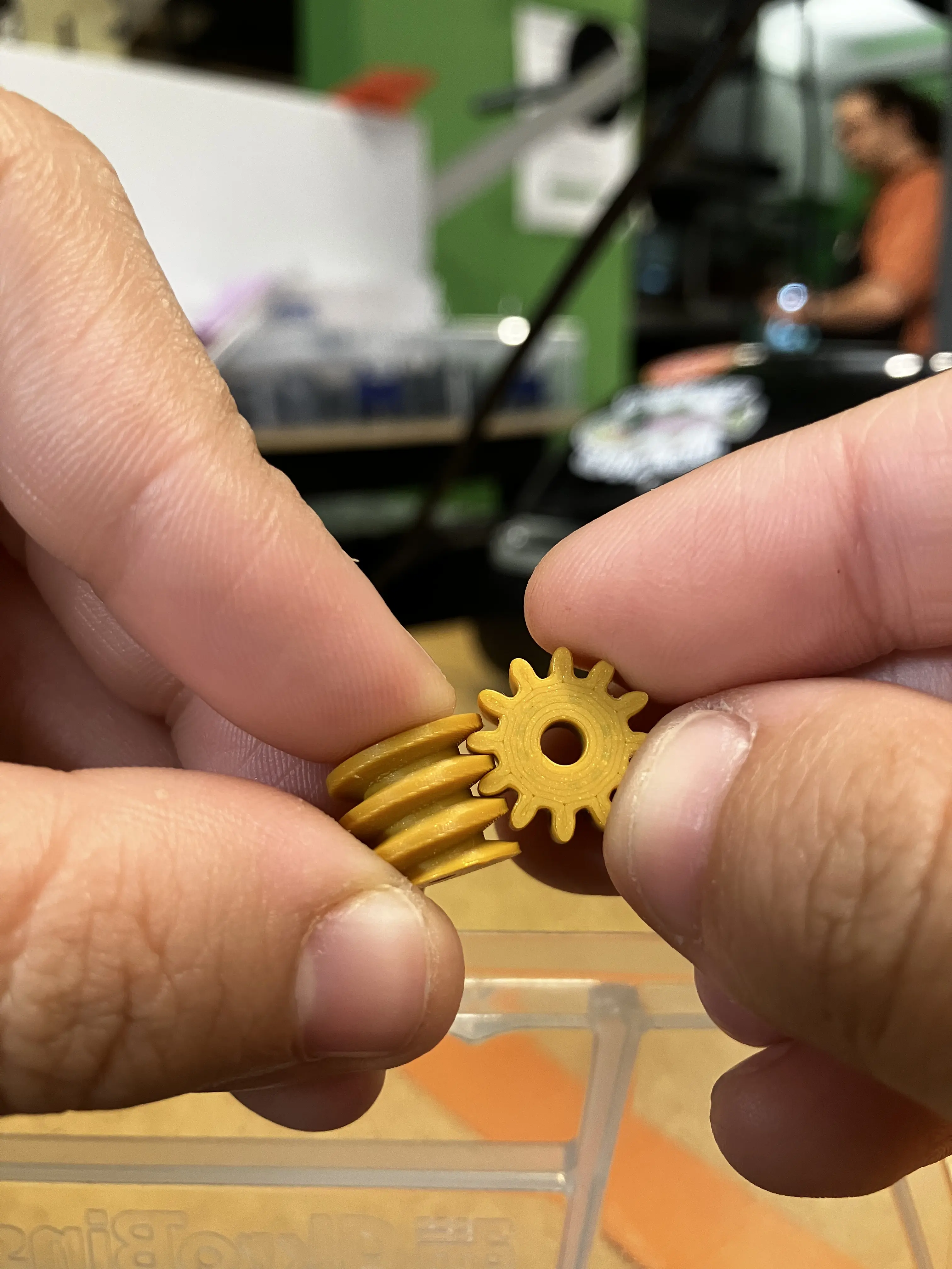
-
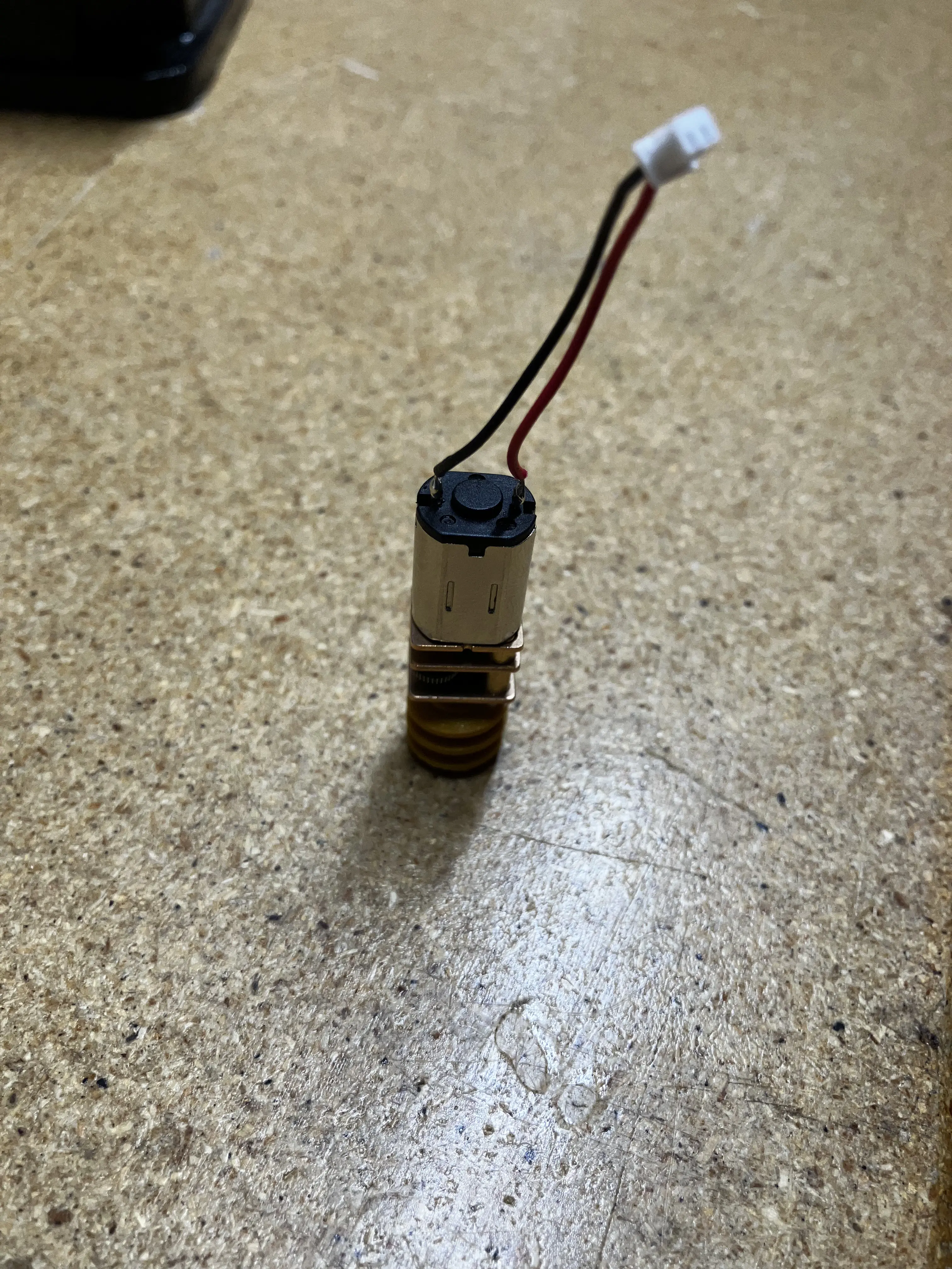
Without applying glue, slide a worm gear onto the shaft of a peel motor.
- Worm gear should fully seat onto the shaft. If not, discard the worm gear.
-
With the worm gear still on the shaft, spin the peel motor in both directions.
- Peel motor should spin smoothly with minimal effort. No clicking or grinding should be heard.
-
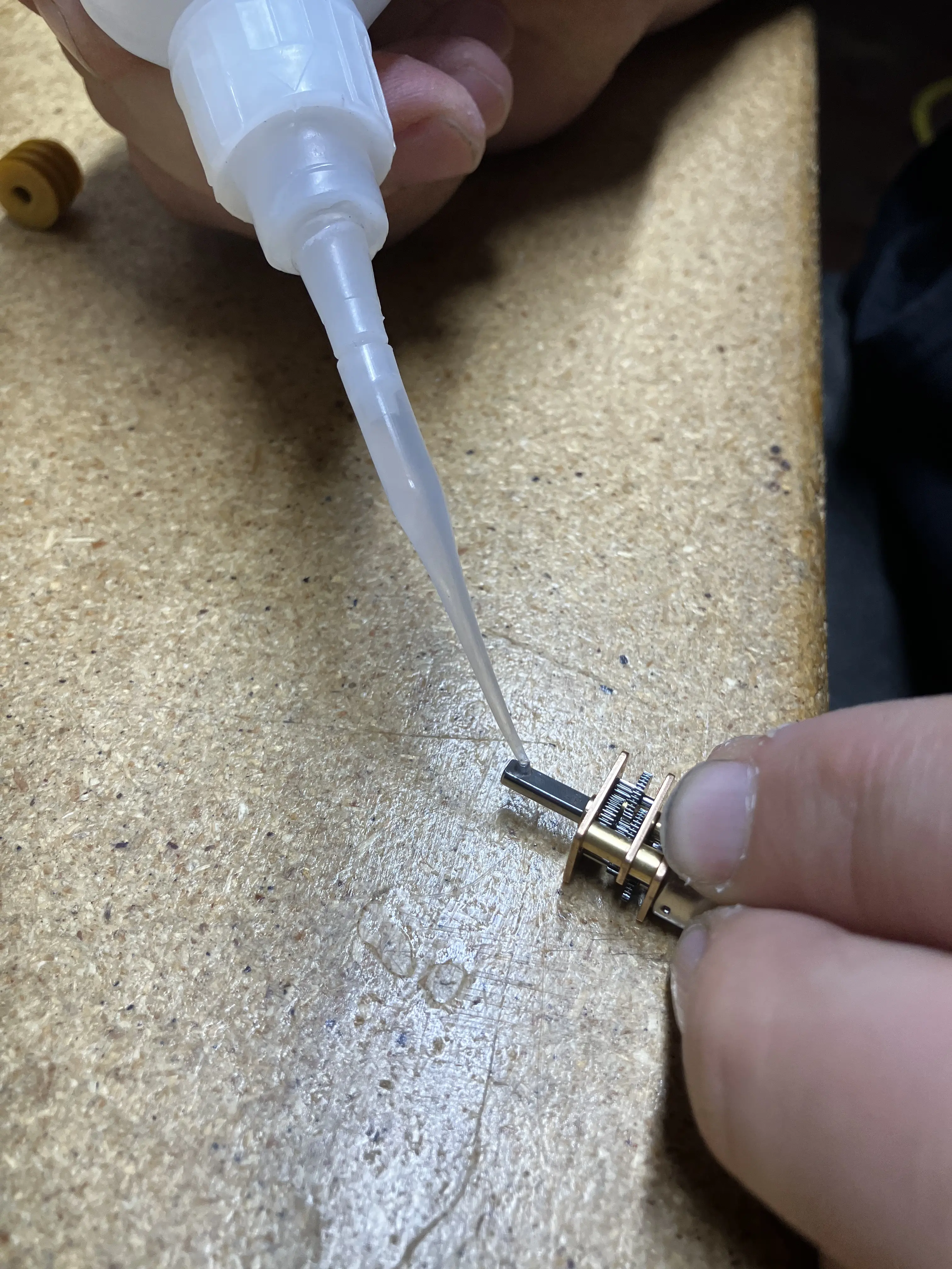
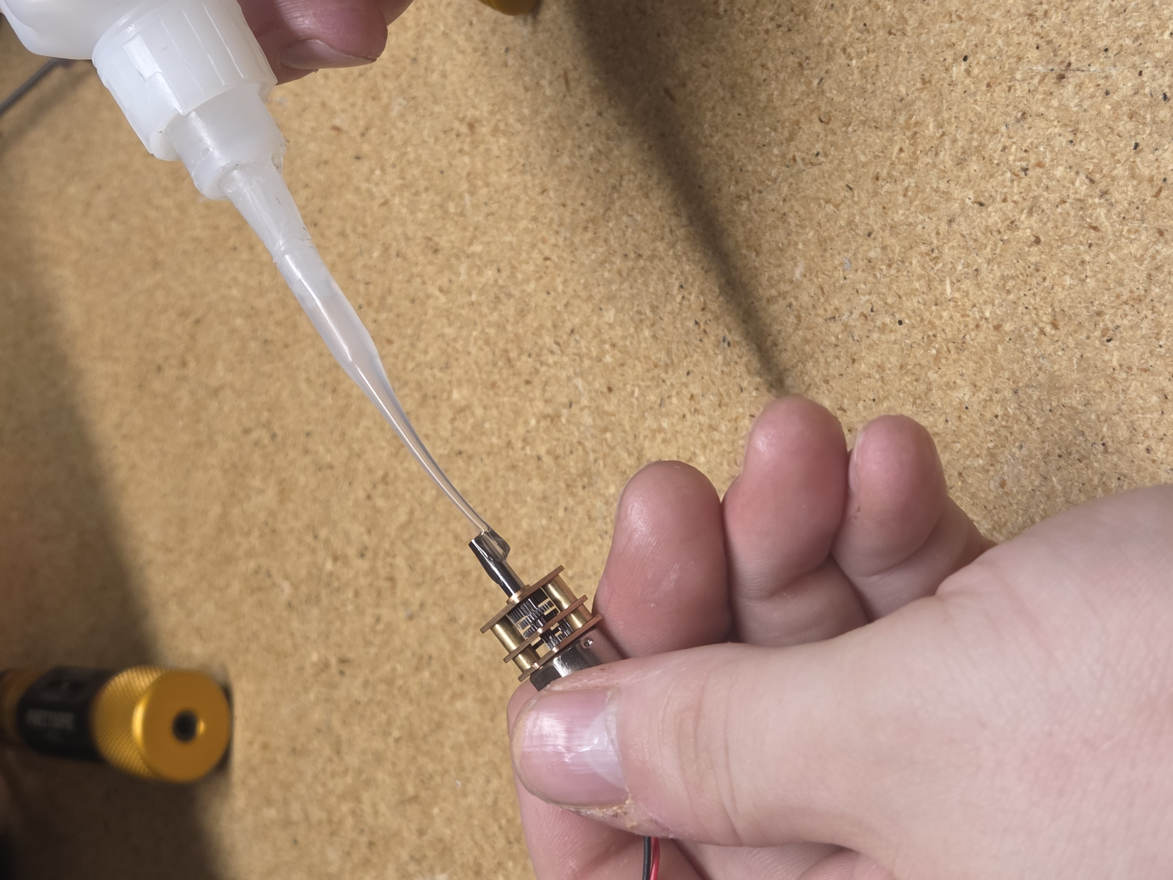
Dispense a 1-2 drops of
LOCTITE 435to the end of shaft onpeel-motor.Start light with the glue because it can get messy
-
Use the tip of the dispenser to spread the glue around the motor shaft.
-
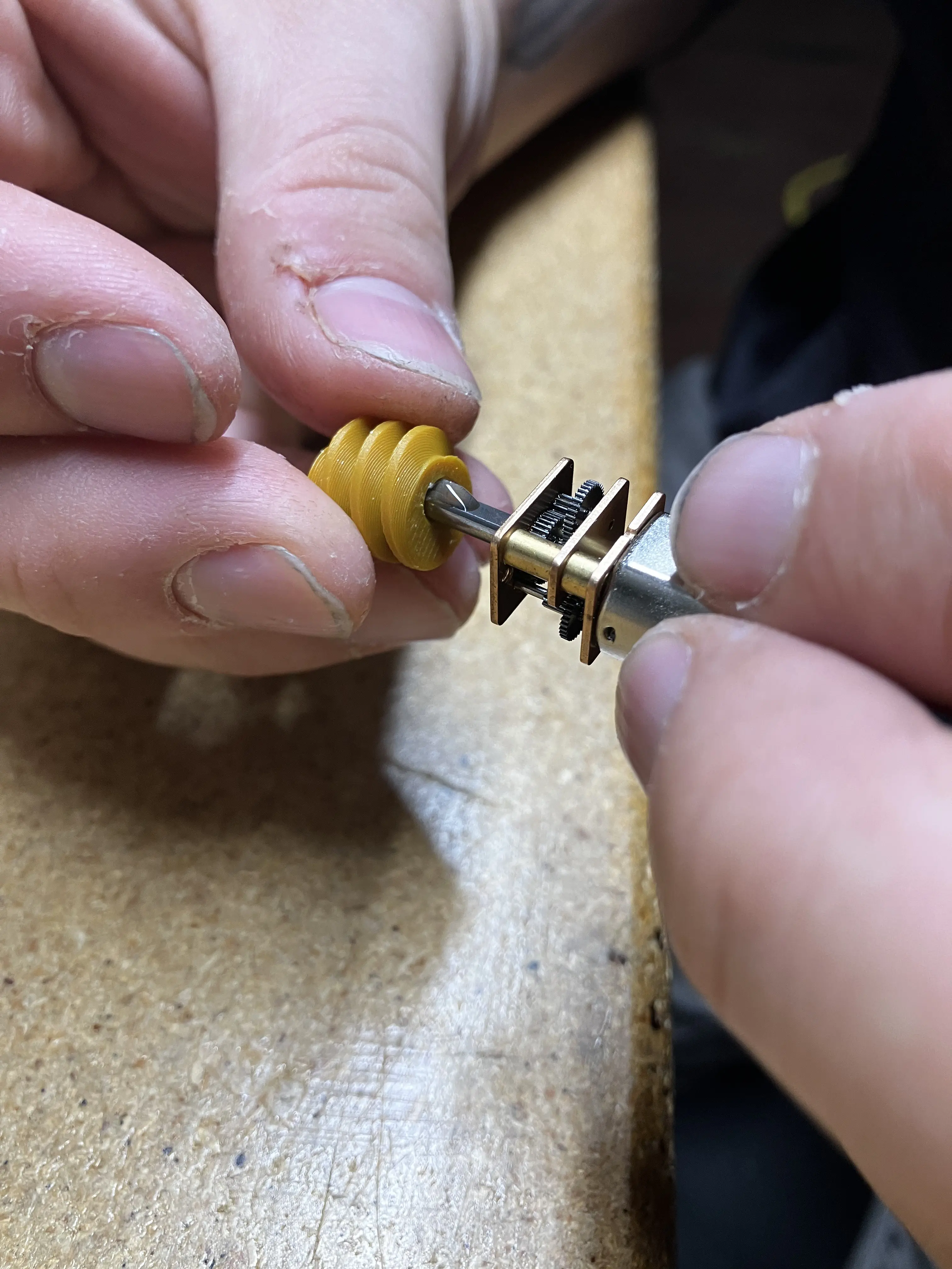
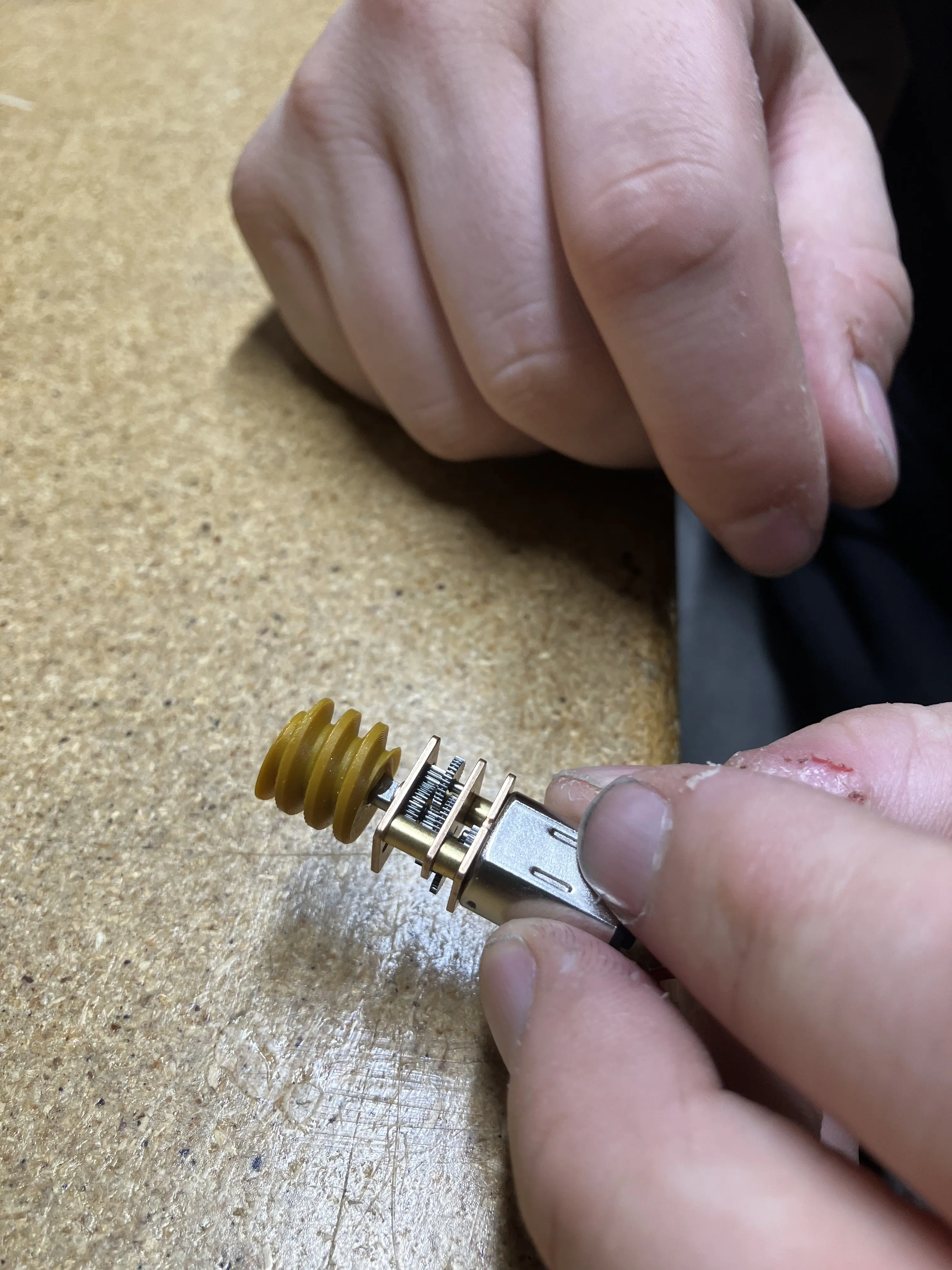
Slide the worm gear all the way onto the shaft of the peel motor.
Press ALL the way on. The print has a depth stop!
-
Place the peel motor assembly on its head in a slot of the foam from which the peel motor came to dry.
-
The assembly will need to dry for at least 3 hours before being installed in a feeder.
-
Once the assembly has dried, move it to the corresponding bin at a feeder assembly workstation.