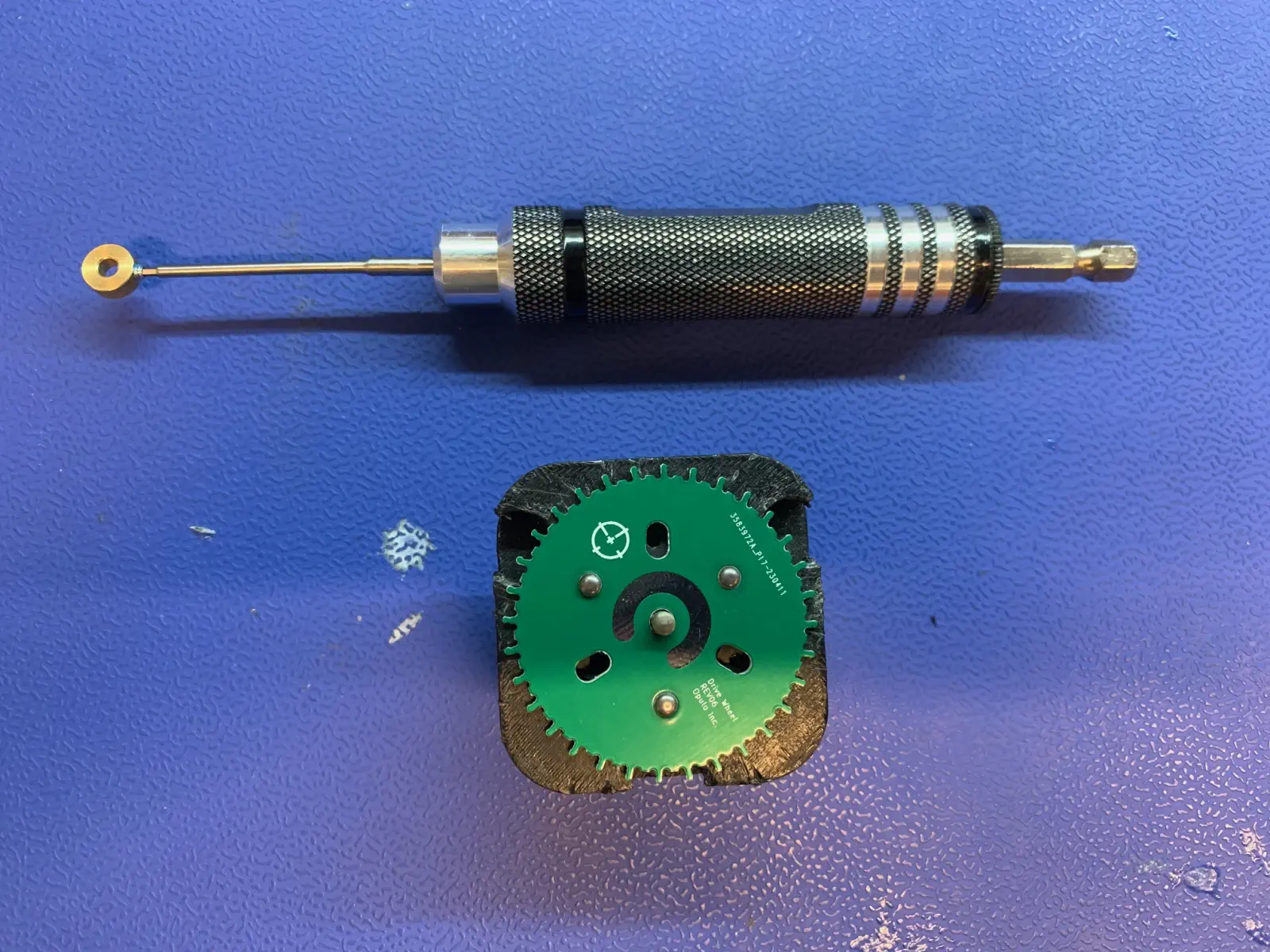
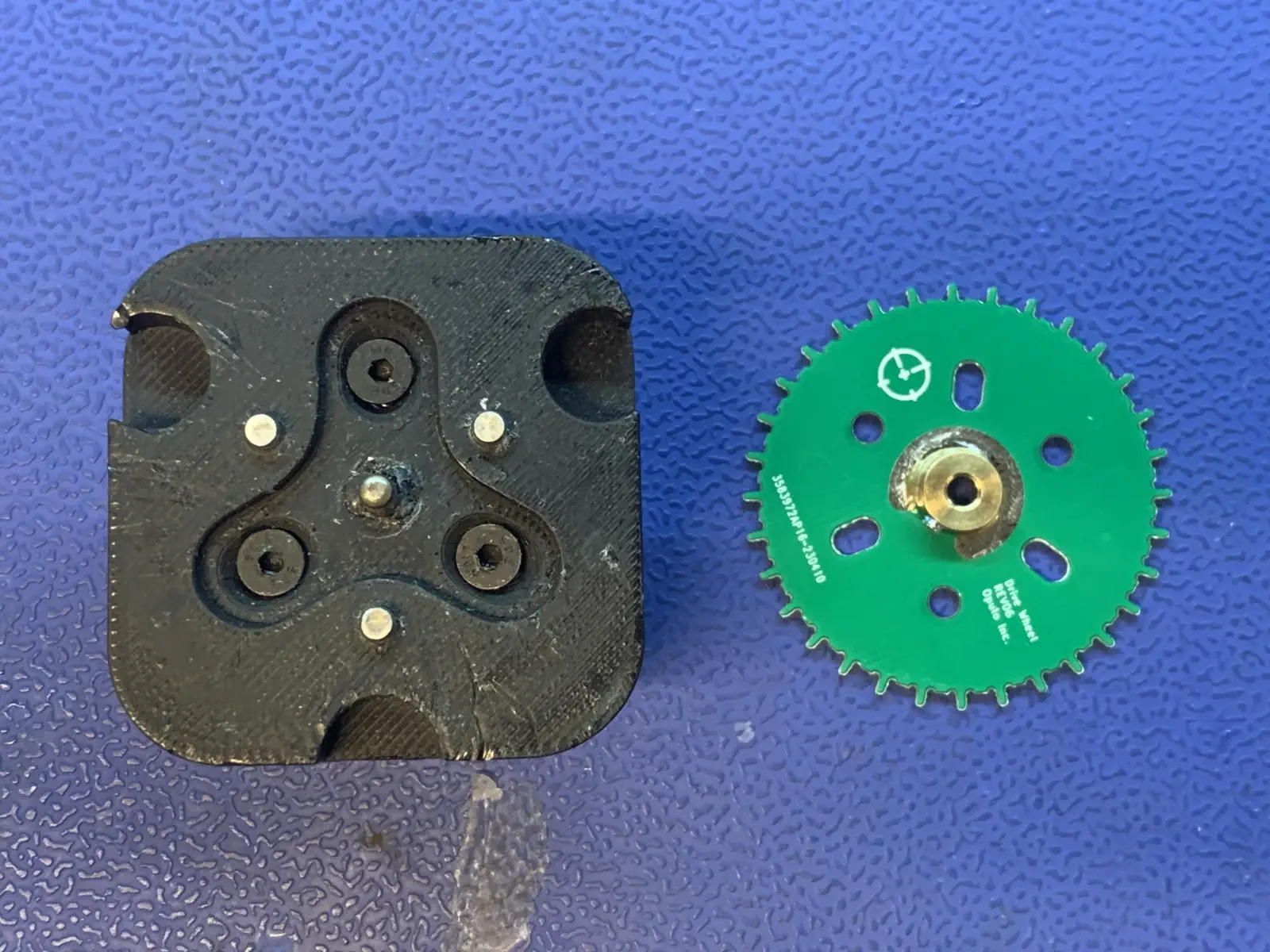
Drive Wheel Assembly
This section will guide the reader on how to prepare and glue the shaft-collar-asm onto drive-wheel to create drive-wheel-asm.
Prepare shaft-collar-asm
-
Install the
set-screwinto theshaft-collarwith a1.3mm hex driver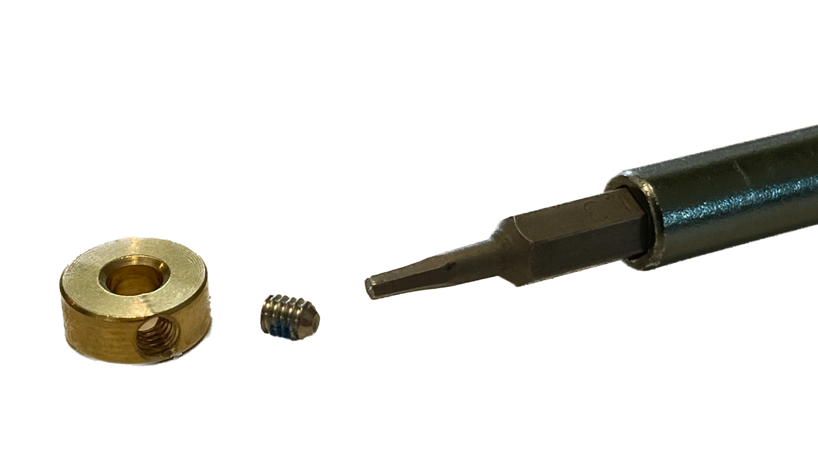
-
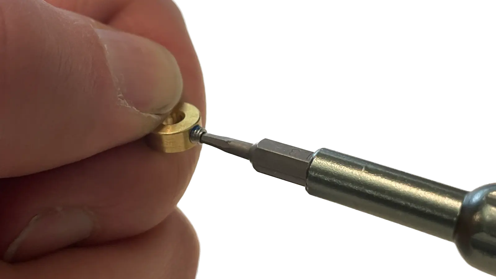
Tighten the
set-screwuntil it nearly passes into the inner bore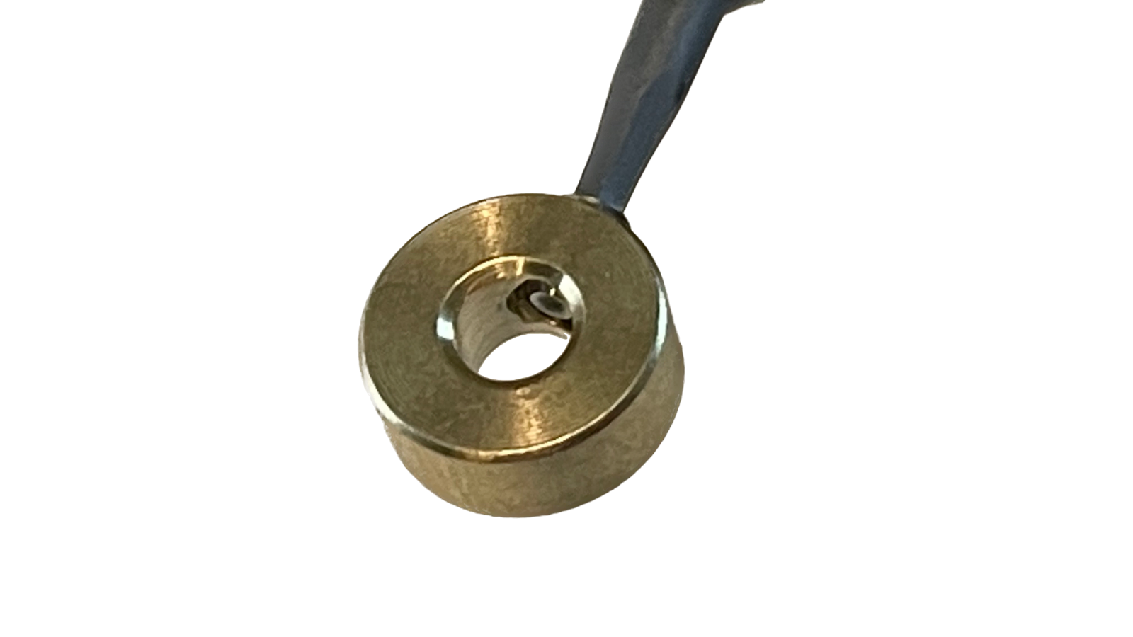
Install shaft-collar-asm and drive-wheel onto shaft-alignment-jig
-
Place
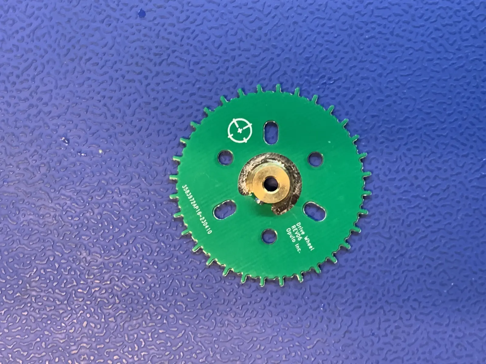
drive-wheelonto theshaft-alignment-jig- Let the 3 slotted pins help align the
drive-wheelinto position - Push the
drive-wheeldown firmly to ensure it is fully seated onshaft-alignment-jig
- Let the 3 slotted pins help align the
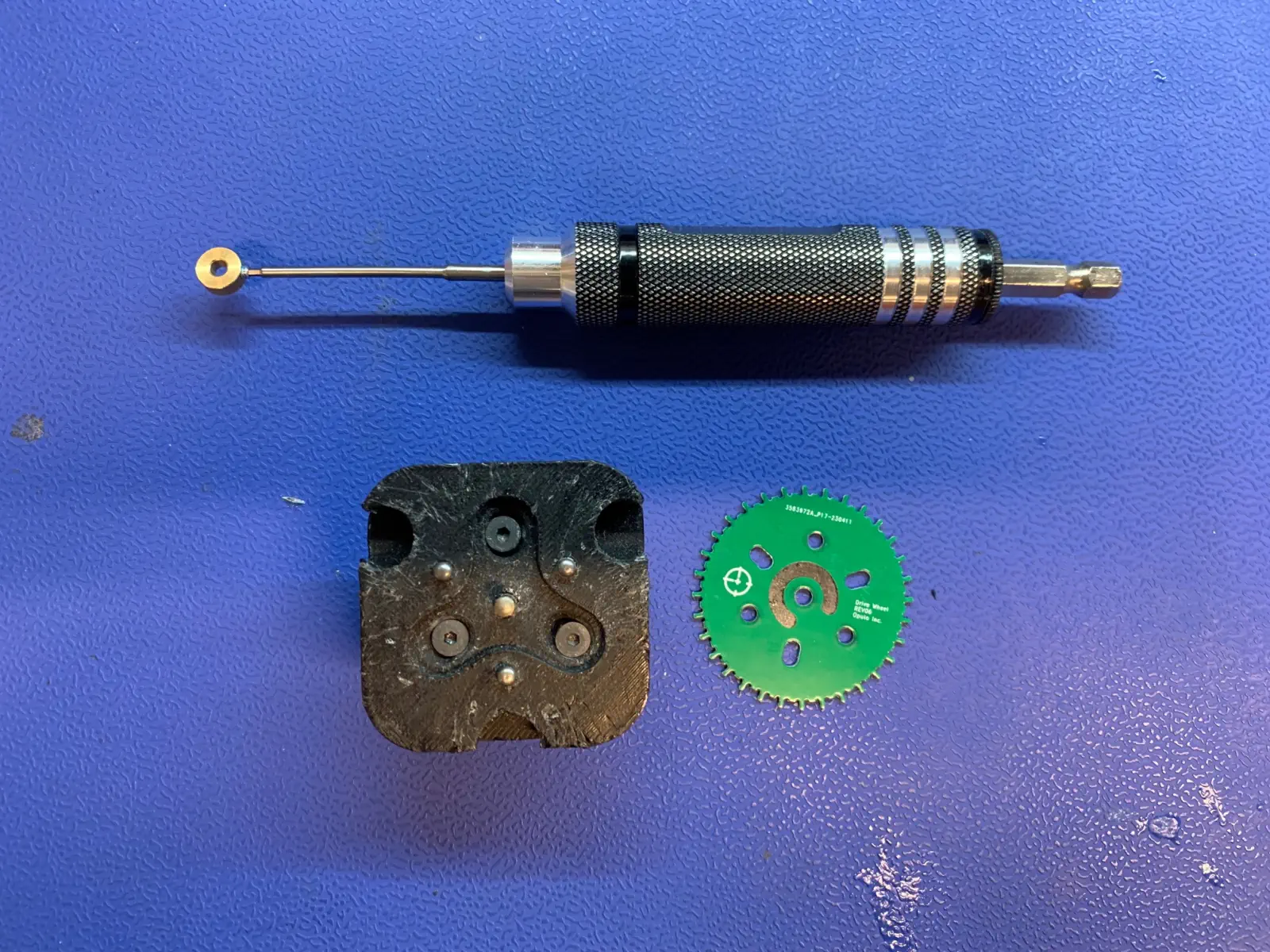
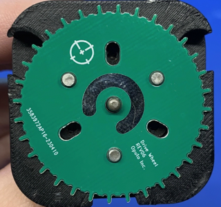
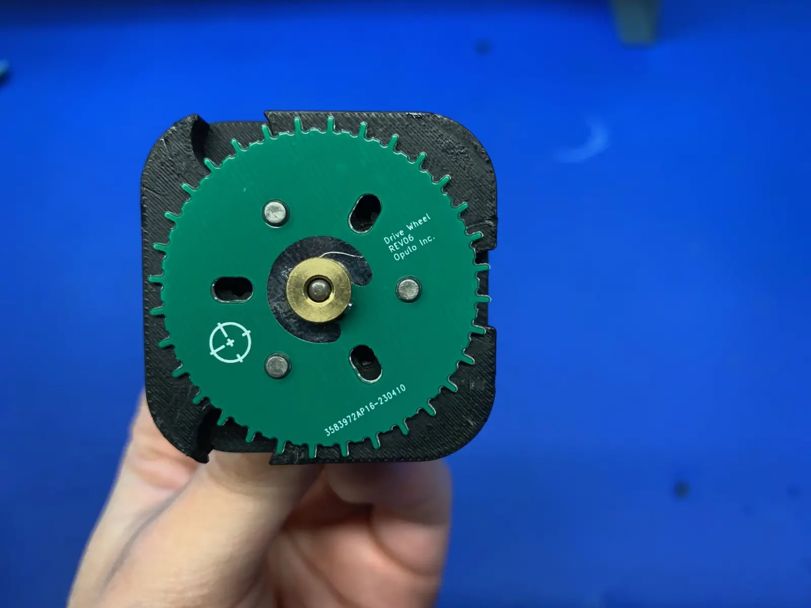
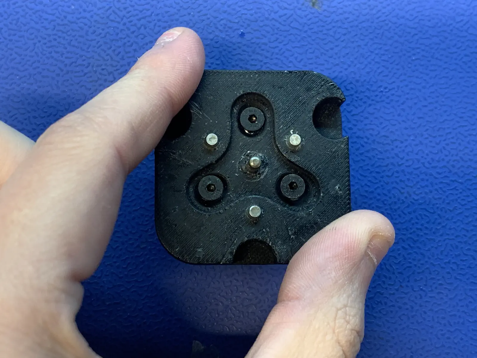
Make sure that no part of drive-wheel is touching the center post of shaft-alignment-jig
* Otherwise, something may become misaligned or unintentionally glued together
* The image below shows a `drive-wheel` with OK clearance from the center post of `shaft-alignment-jig`
-
Place
shaft-collaronto the center post ofshaft-alignment-jig- Orient
shaft-collarso theset-screwis above the green soldermask ondrive-wheel
- Orient
-
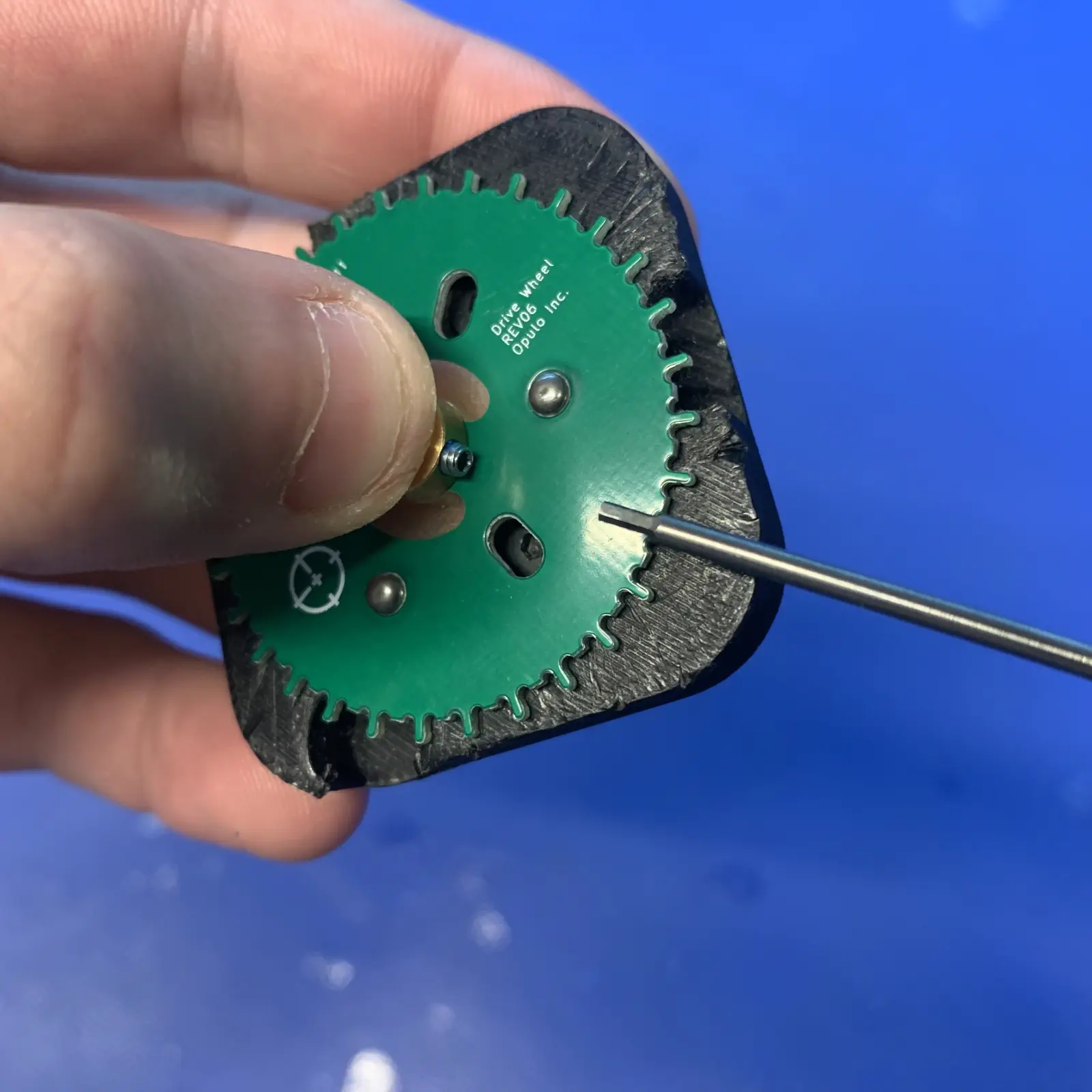
While firmly pressing
shaft-collar-asmdownward, tighten the set-screw to0.2 N/MWarning
Make sure that the shaft-collar-asm does not lift up as you tighten the set-screw
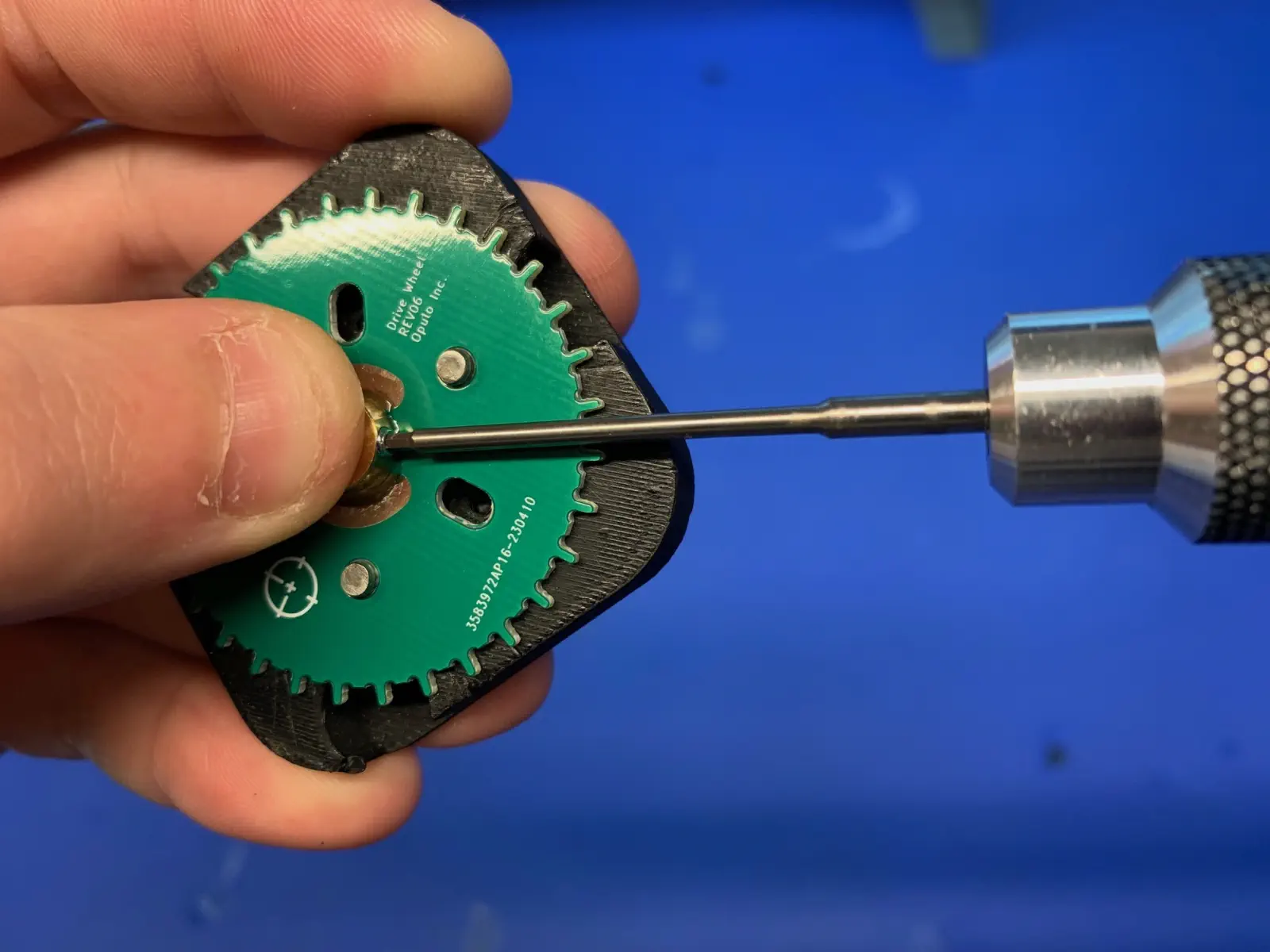
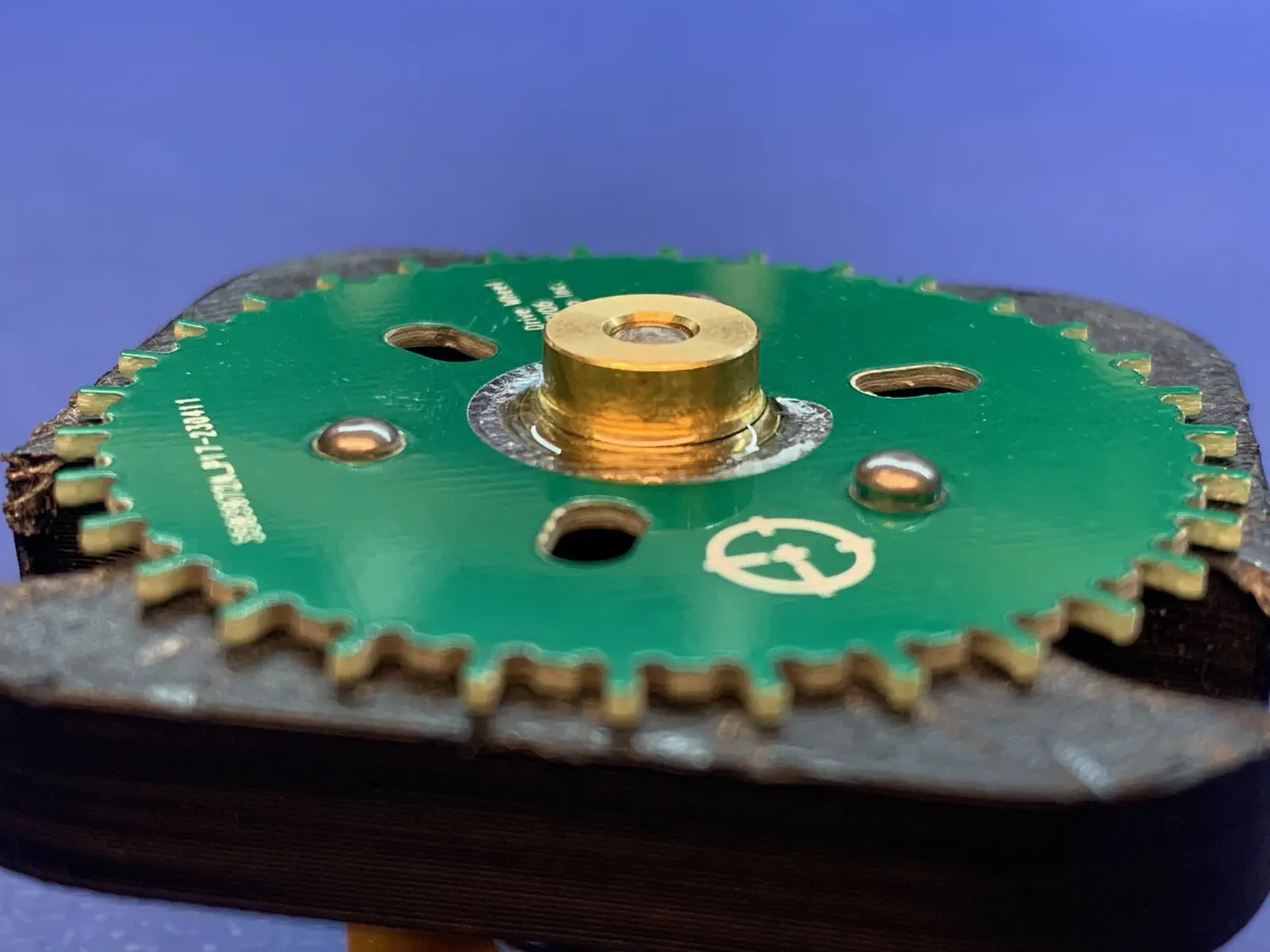
Inspect the WIP assembly for visible daylight between drive-wheel and shaft-collar-asm
If there is a noticeable gap between these two items, adjust and retighten shaft-collar-asm as needed.
-
When the above steps are completed, the WIP assembly should match the image below -
Glue shaft-collar-asm and drive-wheel together
-
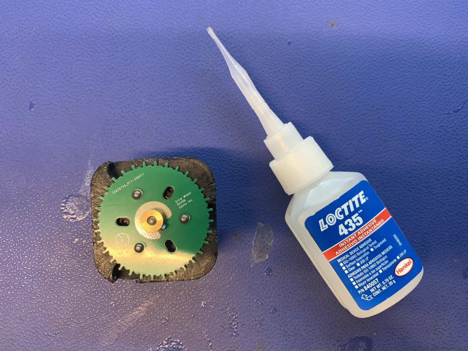
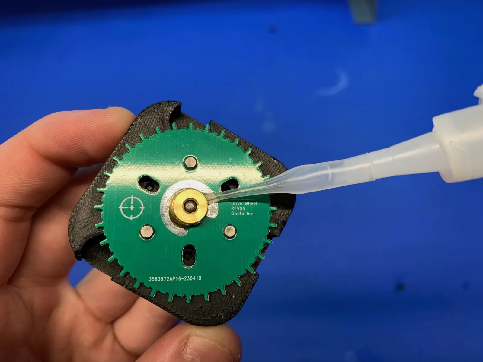
Apply
LOCTITE 435to the seam betweenshaft-collar-asmanddrive-wheel- Rotate around the
shaft-collar-asmwhile slowly dispensing glue - Only apply glue to the C-shaped region of
drive-wheel, being sure to avoid getting glue anywhere near theset-screw
Note
If you accidentally dispense too much glue initially, stop and follow the note below
- Gently swirl the
shaft-aligment-jigwith affixed WIPdrive-wheel-asmaround to spread the glue around the silver C-shaped pad - As usual, be sure to avoid getting glue anywhere near the
set-screw
- Rotate around the
-
Allow the
LOCTITE 435to dry for 180 seconds before proceeding -
Remove the completed
drive-wheel-asmfrom theshaft-alignment-jig- Loosen the
set-screwwhile pinching down on theshaft-collar- This will help to avoid unneeded stress to partially cured glue
- Remove the
drive-wheel-asmby pressing the outer-edges ofshaft-collar-alignment-jigdownward to actuate the jig's ejector pins
- Loosen the
-
Allow the completed
drive-wheel-asmto dry for 1 hour before using it in further processes- The
drive-wheel-asmshould sit flat on a table while it finishes drying
- The
-
Once an hour has passed, check that the
shaft-collaris glued on firmly by nudging it laterally- Note that the outer surface of the glue bond may remain tacky for several more hours
If the shaft-collar moved when testing the glue bond strength, scrap the drive-wheel-asm and record the wasted material
If the glue strength is OK, move the completed drive-wheel-asm to its corresponding storage bin at the feeder assembly workstation