Drag Chain Assembly
This section will guide the reader on how to properly assemble the LumenPNP v4 Drag Chain Assembly.
QC Harnesses
Before assembling the drag chain, QC the individual cable harnesses from the manufacturer.
- Head Harness
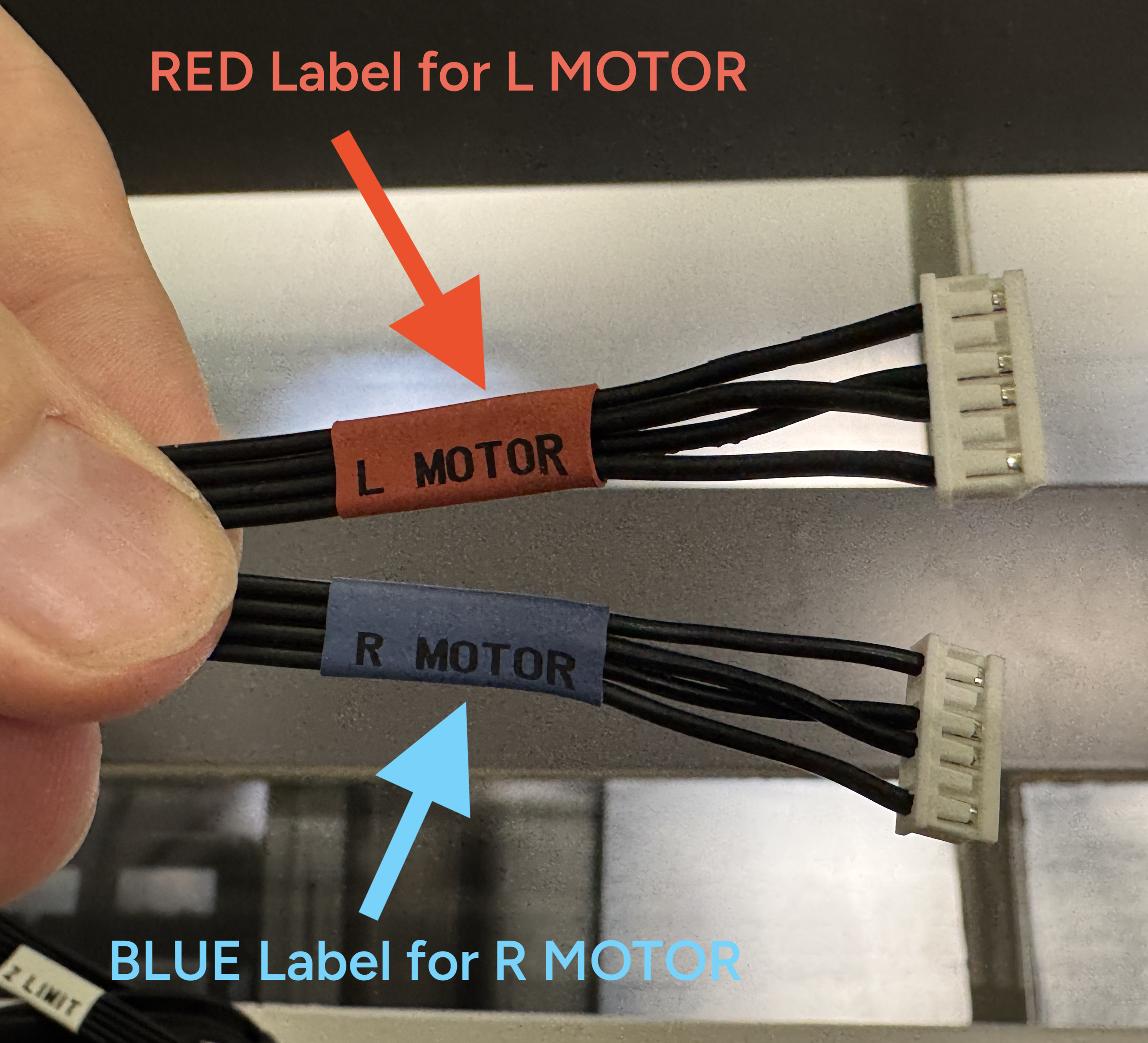
- Labels are all correct
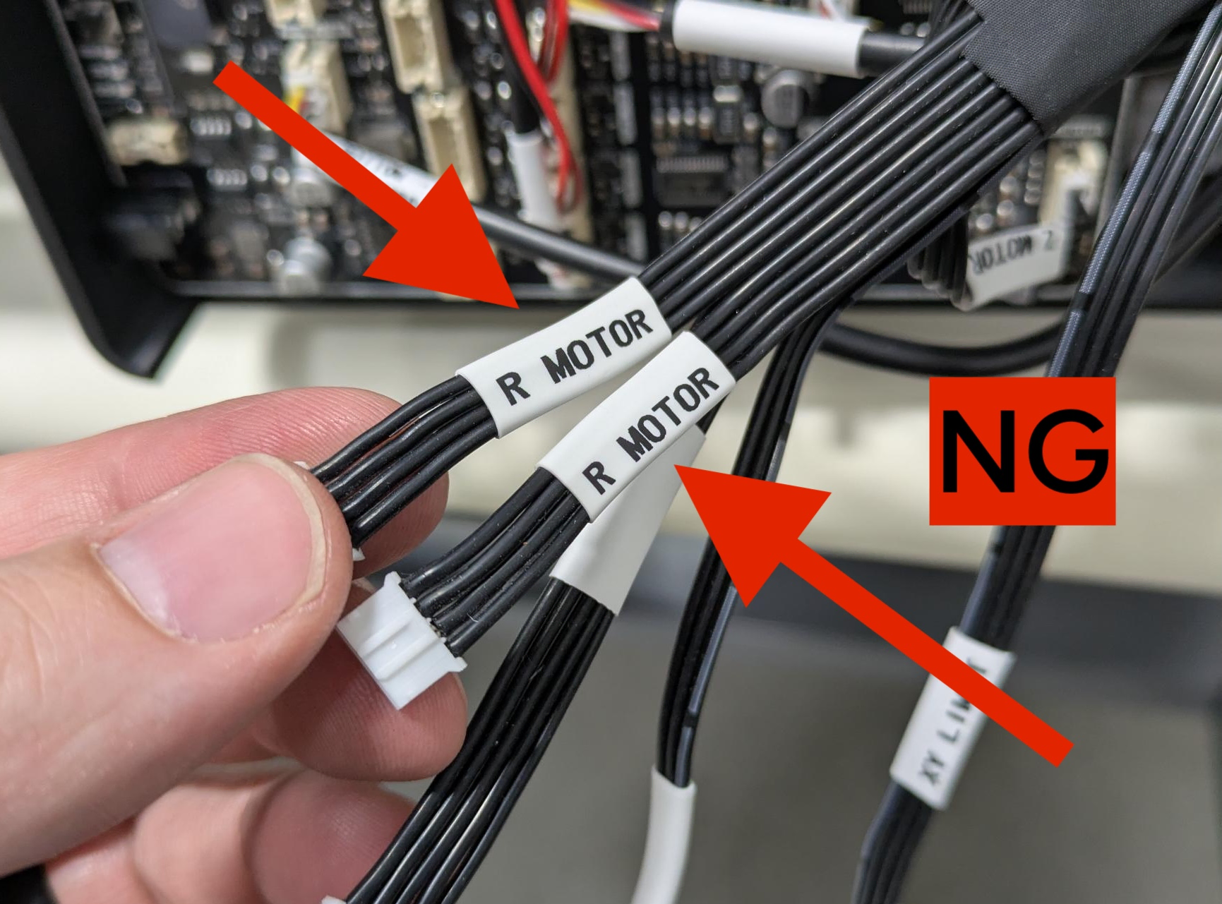
- Colors on head side are correct
Z MOTOR,L MOTOR, andR MOTORcables have inner conductors swapped on the head side only.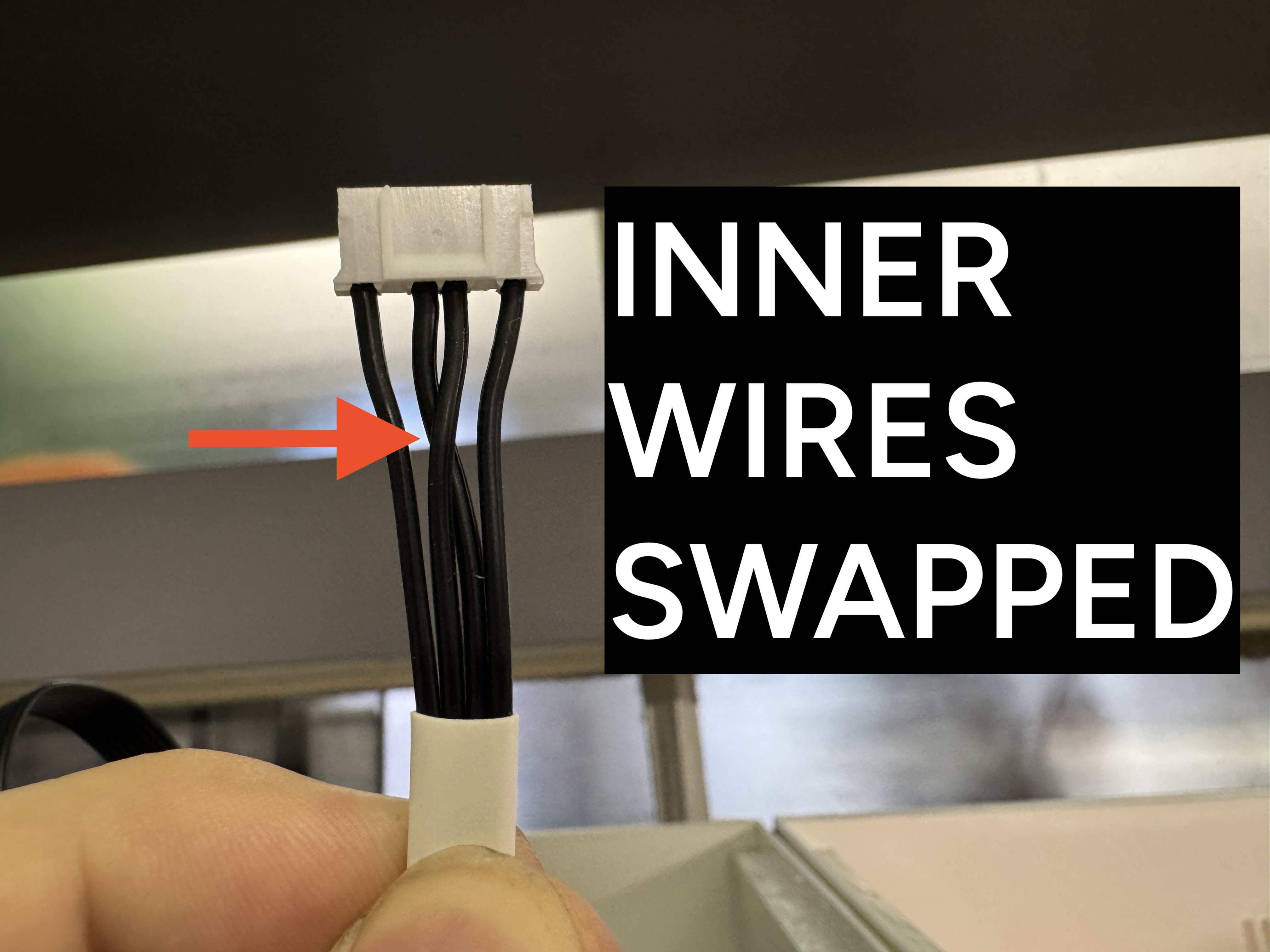
Z MOTOR,L MOTOR, andR MOTORconnectors skips positions 2 and 5 on the head side only.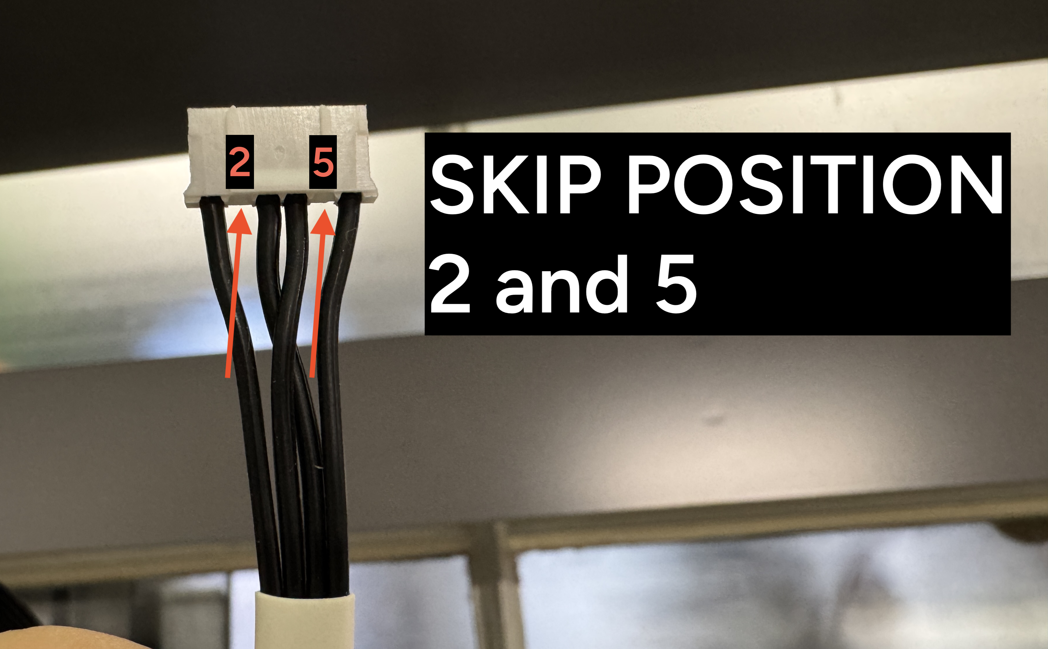
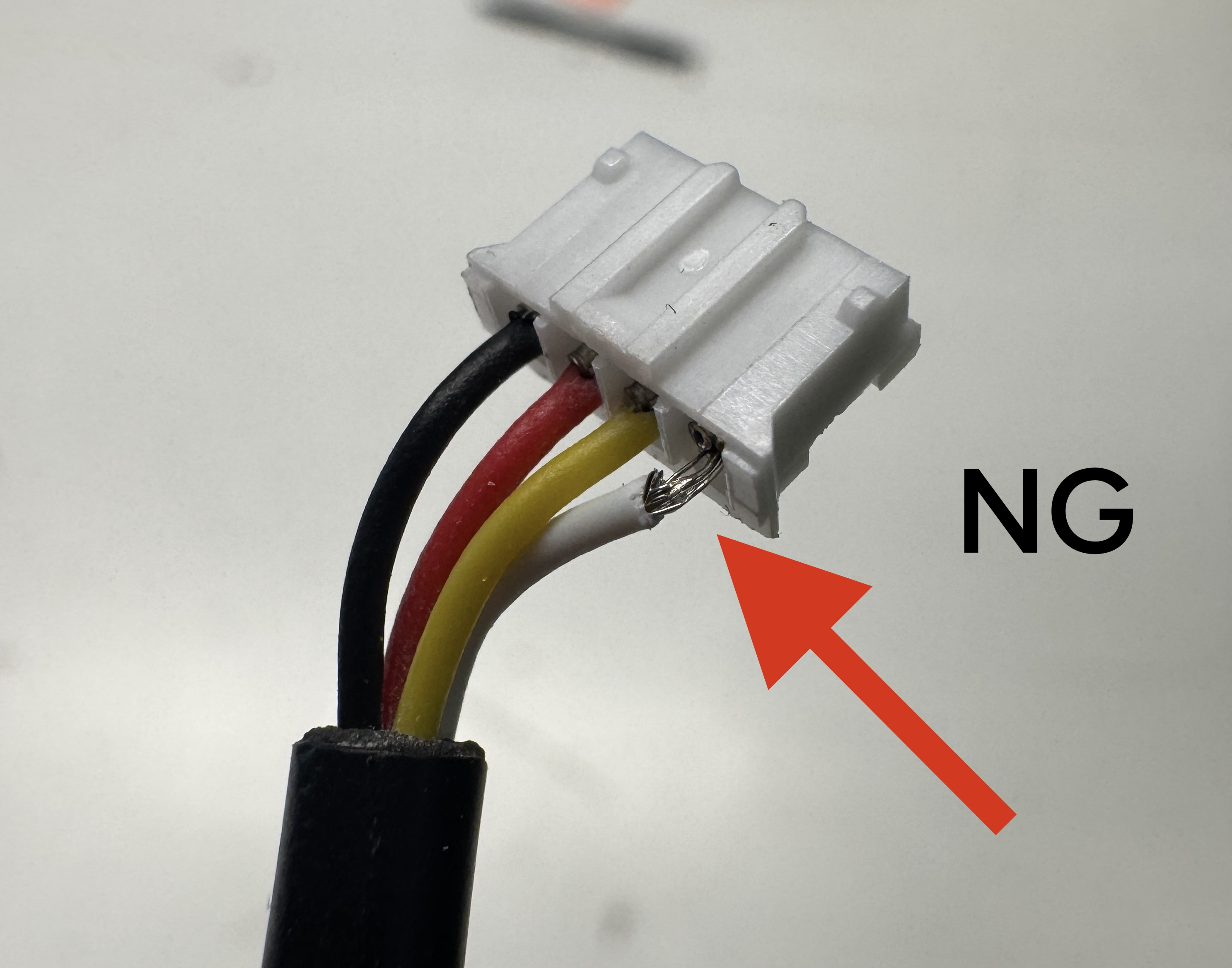
- All crimps are fully loaded
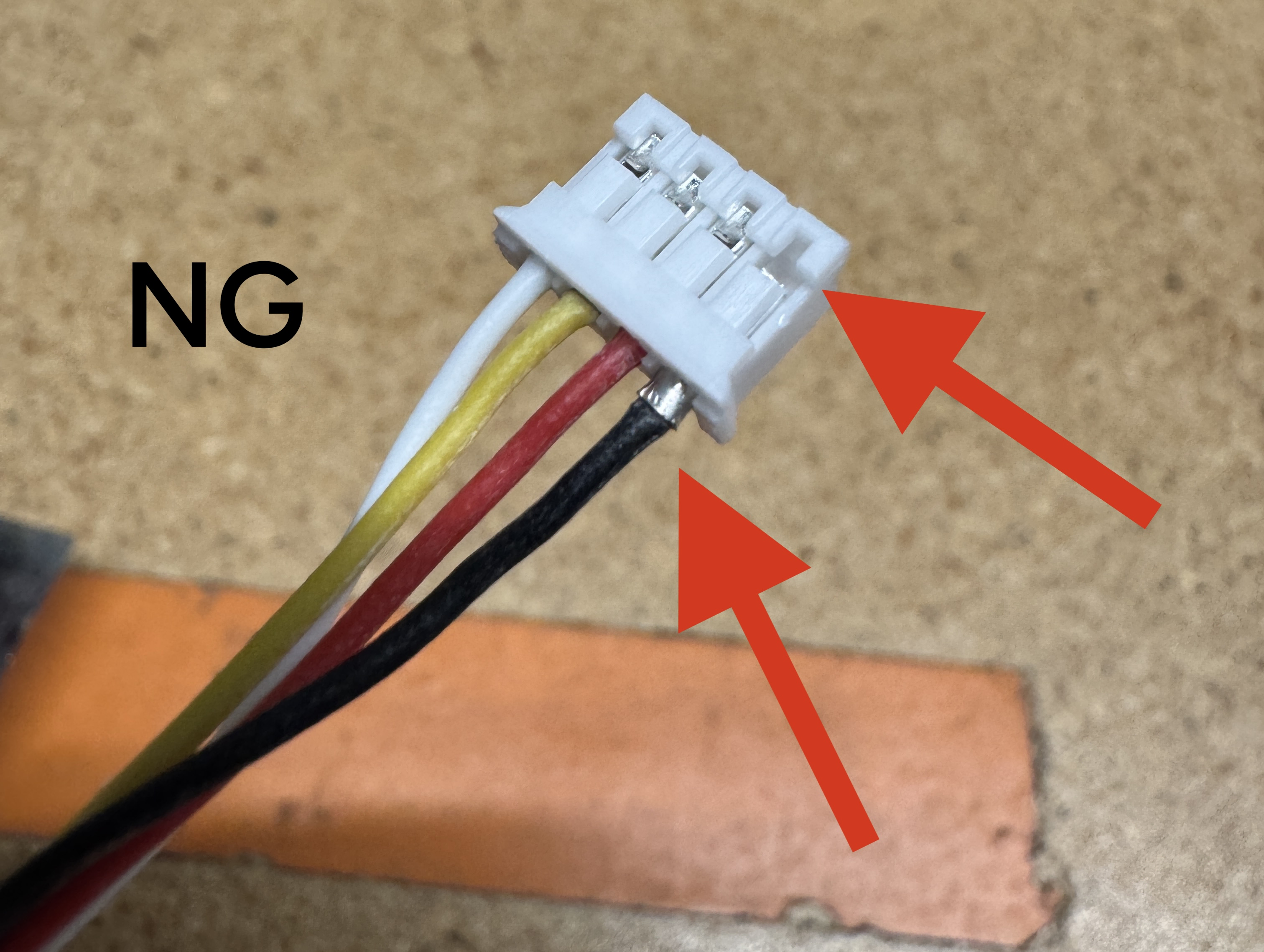
- No loose conductors/Exposed wire
- Labels are all correct
- X Gantry
X MOTORconnector has inner conductors swapped gantry side only.X MOTORconnector skips positions 2 and 5 on the gantry side only.- Labels are all correct
- All crimps are fully loaded
- No loose conductors/Exposed wire
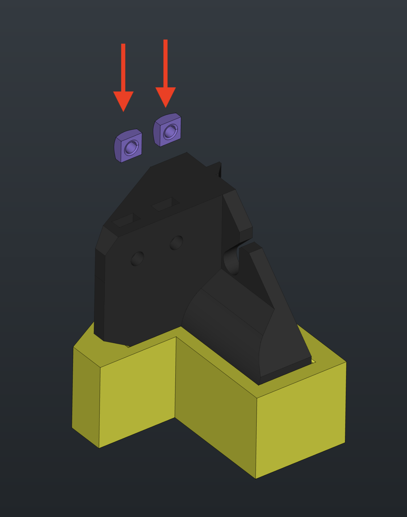
Prepare cable-splay
-
Insert 2x
M5-square-nutintocable-splay- Glue is not required even if the fit is loose
Assemble Drag Chain
-
Insert
cable-splayintobij-jigafter 2xM5-square-nutare inserted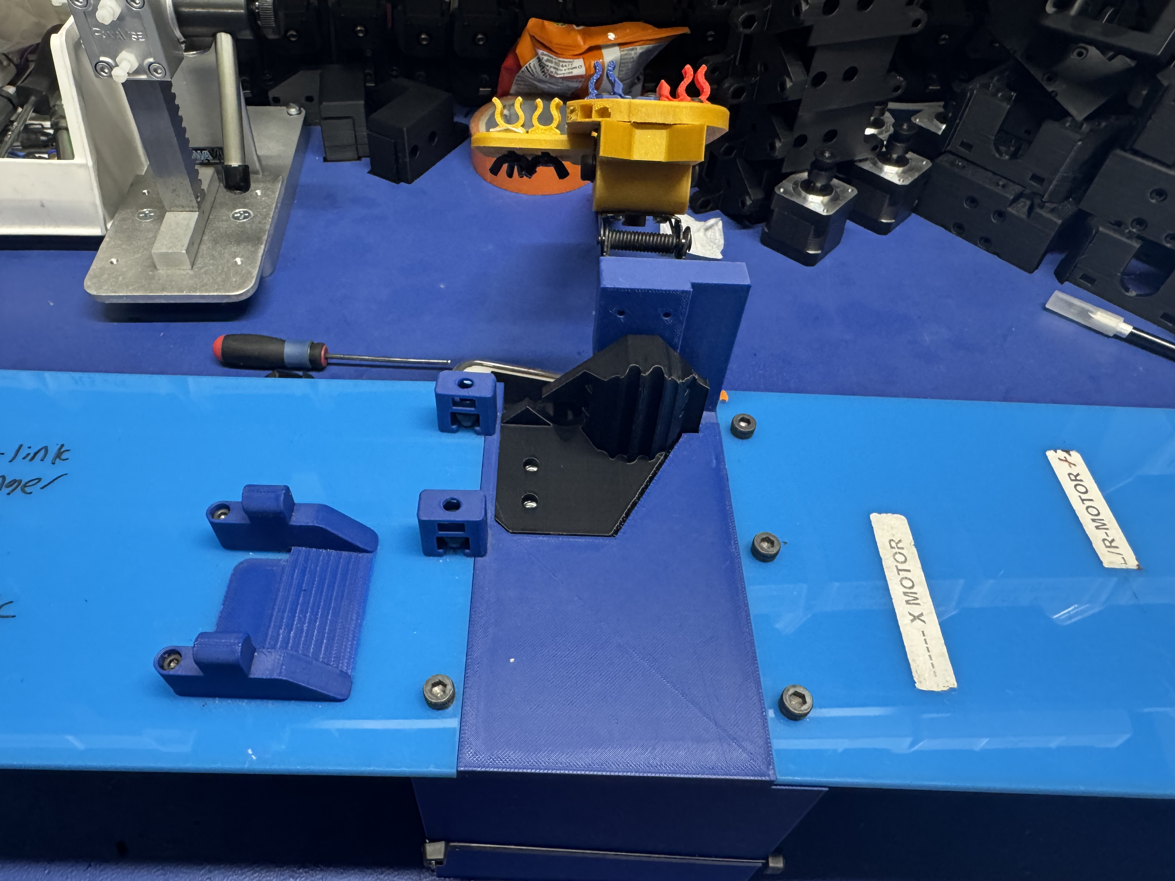
-
Place
34-link-chainand30-link-chainindrag-chain-jigwith the flat side resting on the red area of the jig
-
Screw the chains in place
-
Pop open the drag chain tabs with a screwdriver
-
Open all the tabs to make assembly easier
-
Insert
x-harness-cableintodrag-chain-jig
-
Ensure that the end photographed below is on the left side of the jig
-
-
Insert
top-camera-cableand feed throughdrag-chain-jig
-
Feed
top-camera-cablearound this piece ofdrag-chain-jigas shown below and pull taut
-
Take
pneumatic-tubing(one of each color) and insert into the adapters ondrag-chain-jig
-
Feed through
drag-chain-jigand pull taut. Ensure the twopneumatic-tubingtubes don't cross over each other when feeding arounddrag-chain-jig
-
Insert
pneumatic-tubingin opposite order on the bottom end ofdrag-chain-jig
-
Prepare
head-harnessand ensure that mobo side ofhead-harnesshas proper spacing. Inspect the cables for any loose crimps, reworking as needed, before continuing
-
Pull
head-harnesstaut
-
With the thinner cable facing you, feed
head-harnessthroughdrag-chain-jiguntil the first ring of tape on the toolhead side ofhead-harnessis at the beginning of34-link-chain
-
Pull
head-harnessall the way through and ensure the cable is taut
-
Close all of the tabs on
34-link-chainand30-link-chain
-
Use
presser-toolto secure the tabs
-
Disconnect
pneumatic-tubingand the usb side oftop-head-cam.
-
Unscrew
34-link-chainand30-link-chainfromdrag-chain-jig
-
Remove
34-link-chainfromdrag-chain-jigfirst. Bring it to the bottom side of30-link-chainwhile keeping it face up
-
Remove
30-link-chainfromdrag-chain-jig. Flip both chains upside down in preperation for placement into thebij-jig
-
Insert both chains into
bij-jig
-
Secure chains into
bij-jigwithm5x16-flat-head. Use high torque
-
Raise the rail attached to
bij-jigand insertpneumatic-tubinginto color-coded slots
-
Zip tie the tubing and cables into the grooves of
cable-splay
-
Feed
head-harnesscables underneath the cables zip tied tocable-splay
-
Seperate
top-light-cablefromz-limit-cables
-
Pull
top-light-cablethrough to line marked on the back side ofbij-jig
-
Do the same for
top-camera-cable
-
Zip tie
top-light-cableandtop-camera-cablein place
-
Pull
head-harnesscables taut. The cables should reach to or beyond the sticker onbij-jig
-
Bundle all cables and tubing together and place a rubber band to keep them together
-
Do the same for the cables at the top, making sure not to bend
pneumatic-tubing
OQC Checks
-
Inspect the cable-splay side of
drag-chainand confirm the following cables are present and installed in the correct directionLMcable: 6-pin connector with a redLMlabelRMcable: 6-pin connector with a blueRMlabel
-
Confirm the following vacuum tubes are present at both ends:
- Red
4mm-pneumatic-tubing - Blue
4mm-pneumatic-tubing
- Red
-
Confirm no vacuum tubes are pinched closed by the rubber banding
- Confirm 3x
zip-tieused incable-splayare trimmed flush and present - Confirm presence of
top-camera-cable -
Confirm presence of
x-harnessand double check thatx-harnesshas the correct orientation
If all checks pass, place the completed drag-chain into a yellow NEEDS QC bin found on the pack-out shelf while it awaits review