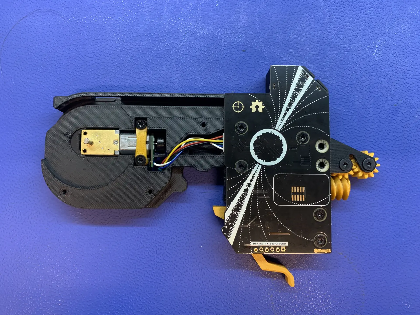
Final Assembly
Motherboard Installation
-
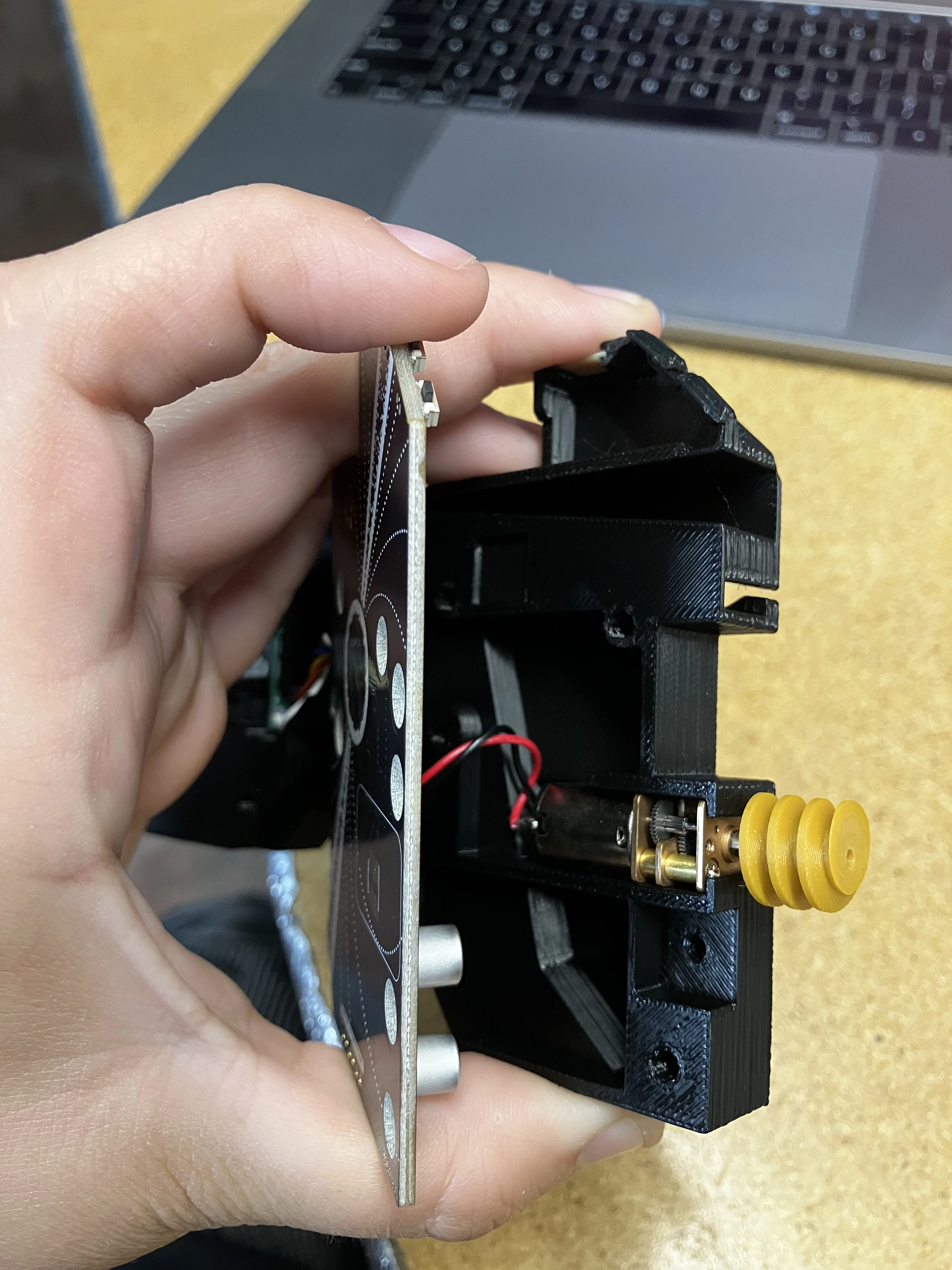
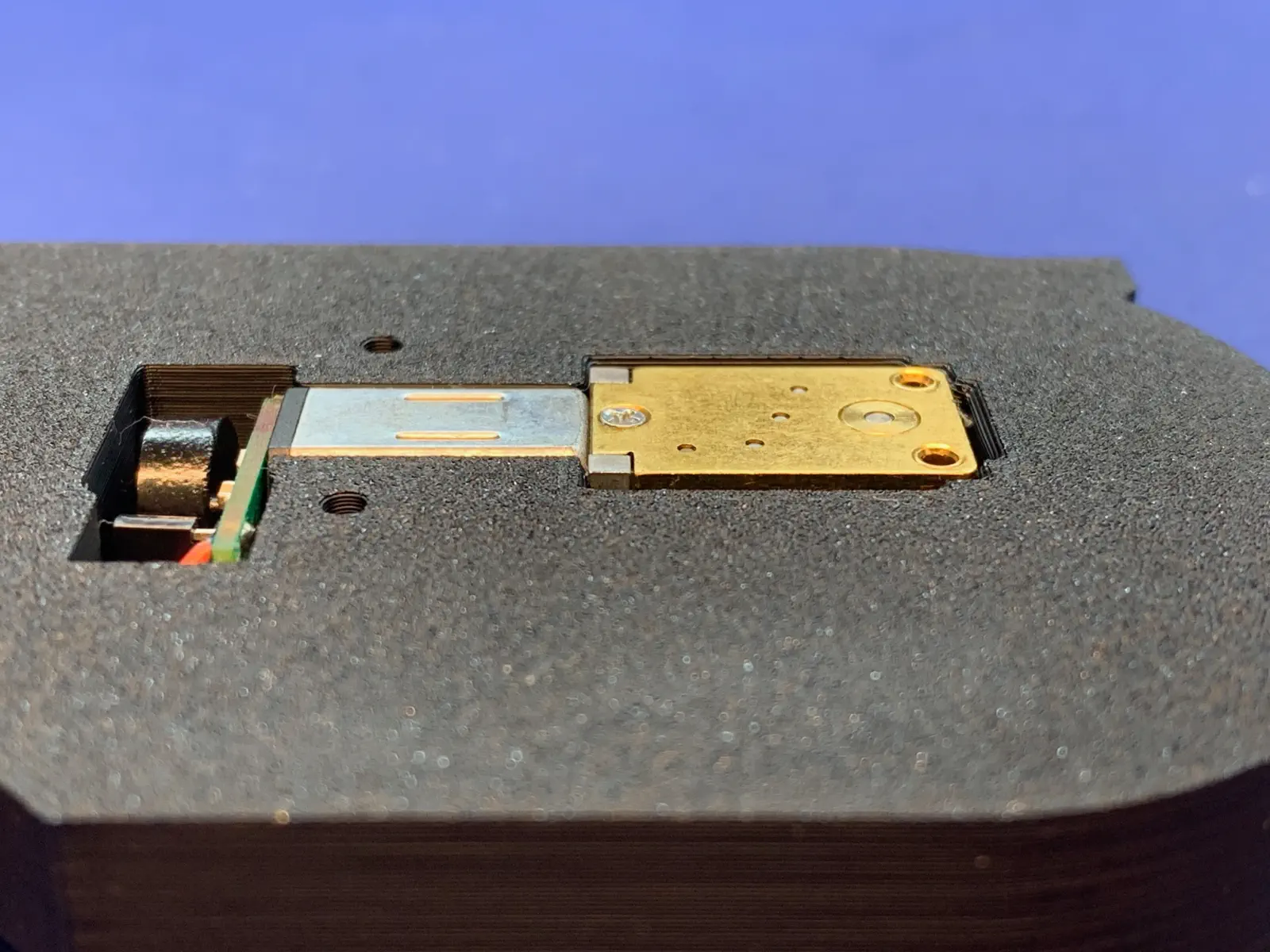
Pull on the
peel-worm-gearand ensure it's properly glued onto the peel motor shaft. Twist the worm gear to make sure it spins the motor easily.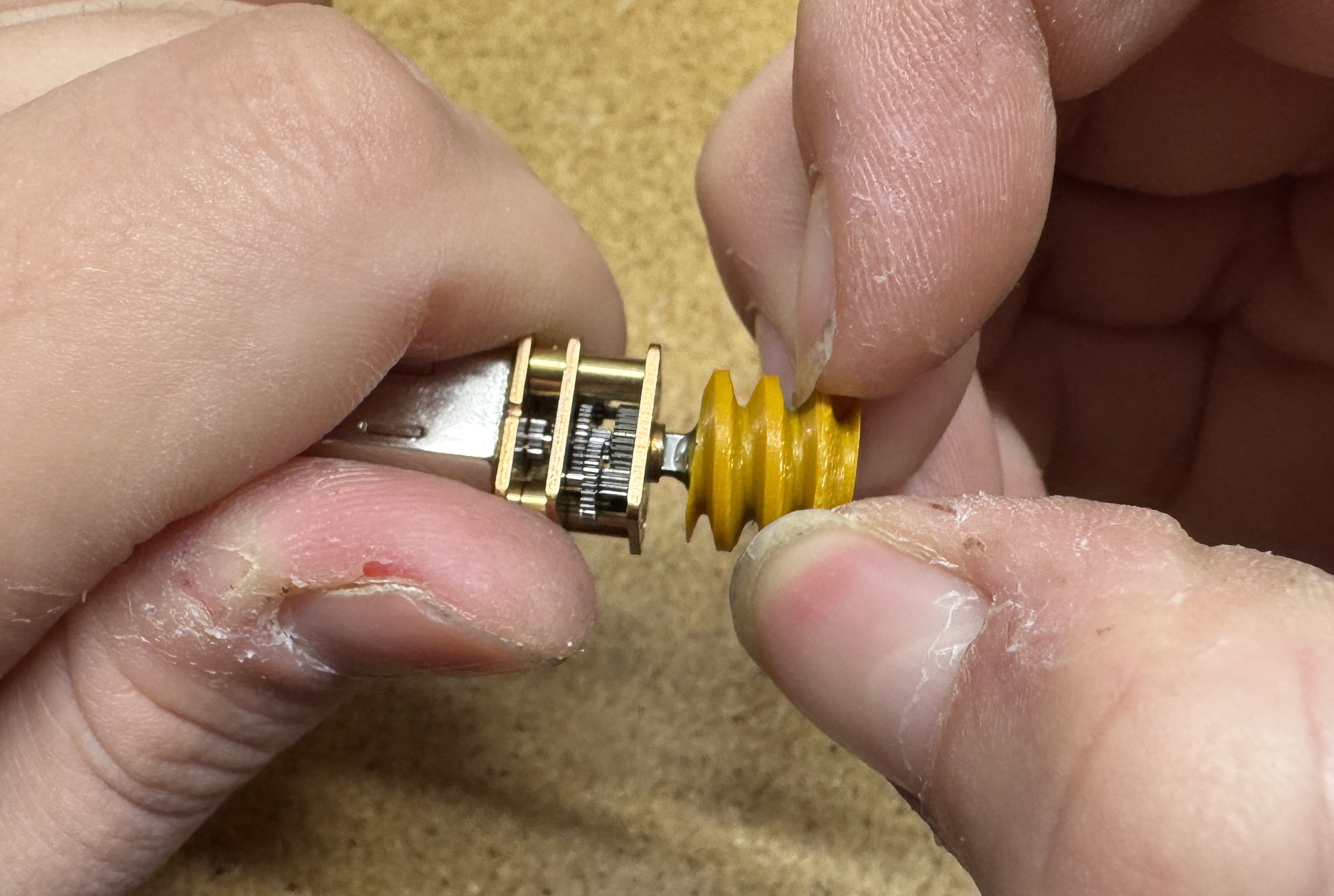
-
Plug the
peel-motor-asmanddrive-motorto their respective pins.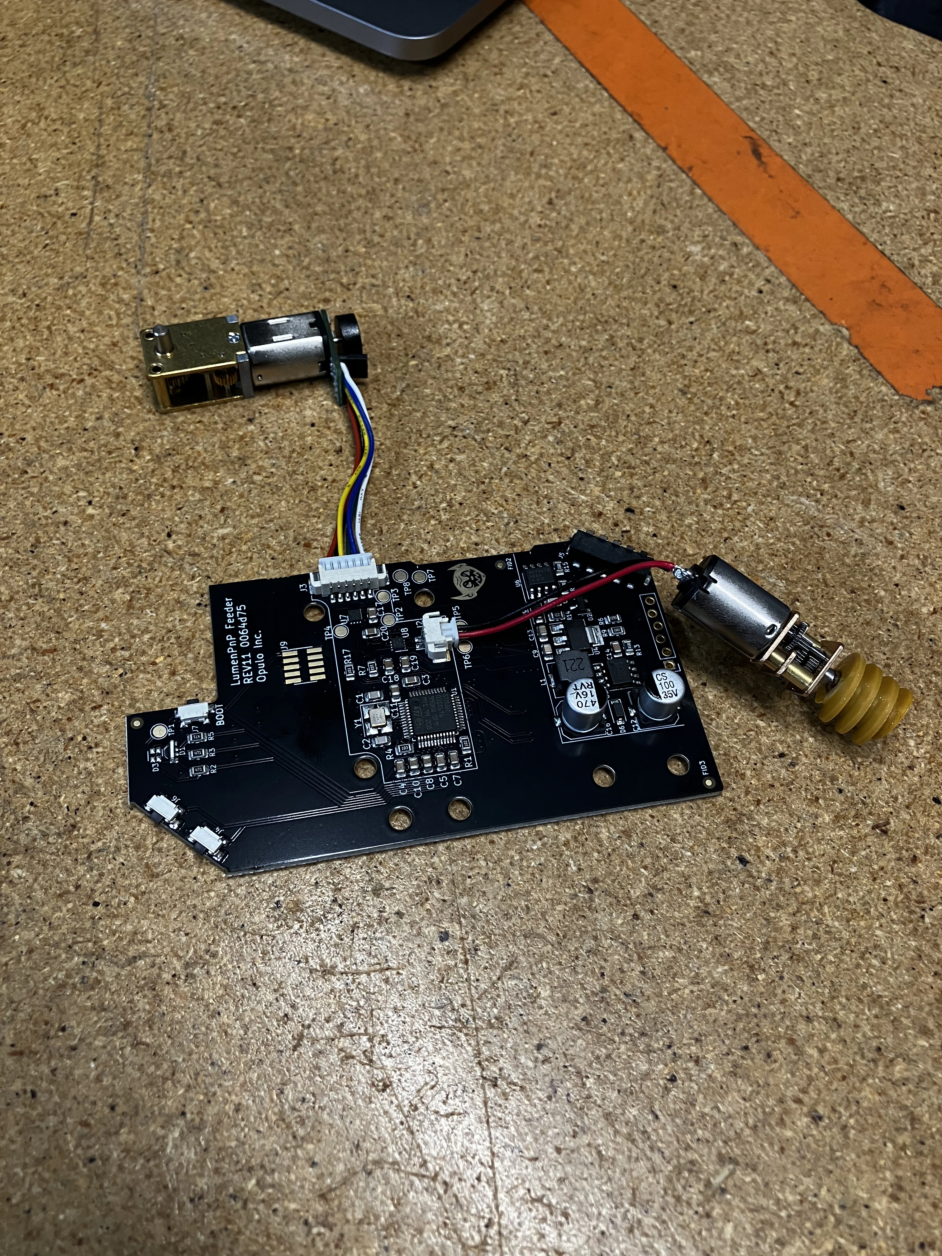
-
Press
drive-motorinto its cavity while ensuring it is flush with the back offeeder-frame. This helpsdrive-motorstay stable as we place the board into the frame.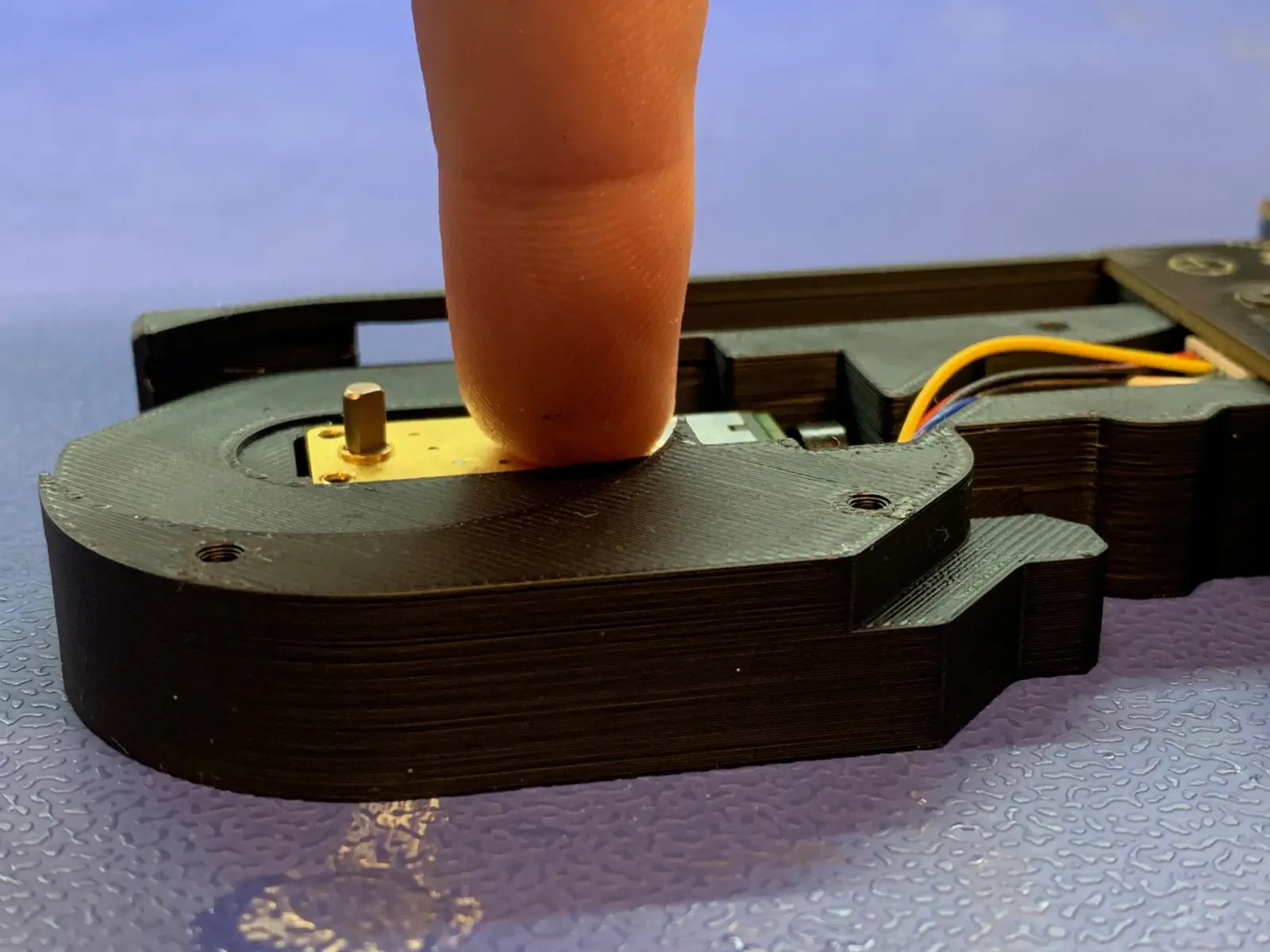
-
Do NOT twist
feeder-mobocables inside frame.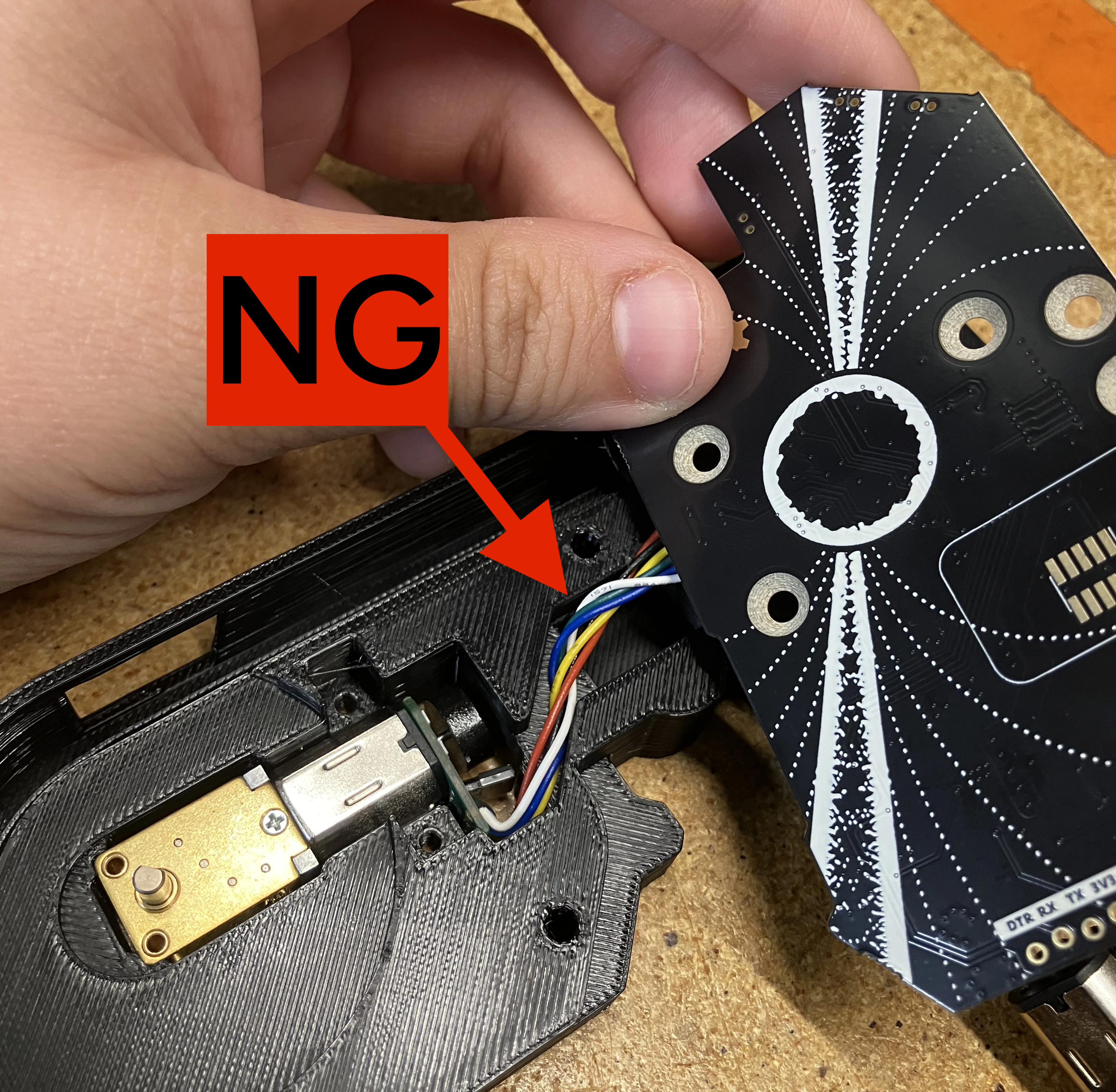
-
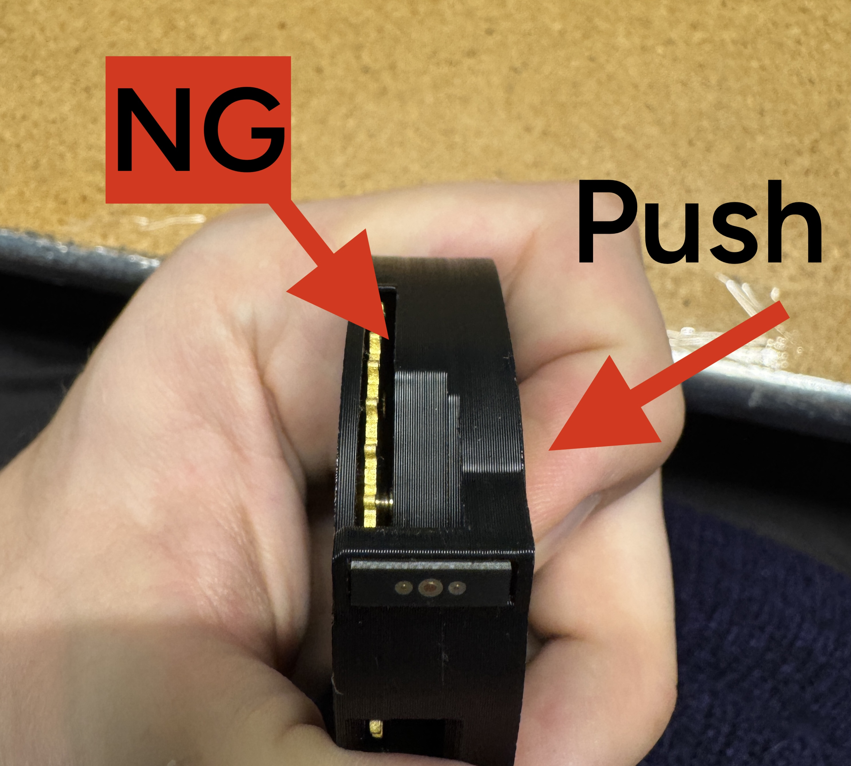
Place the peel motor assembly into its slot in the feeder.
- Orient the red wire upwards to make sure the PCB can lay flat in the frame once the wires are tucked behind the PCB.
-
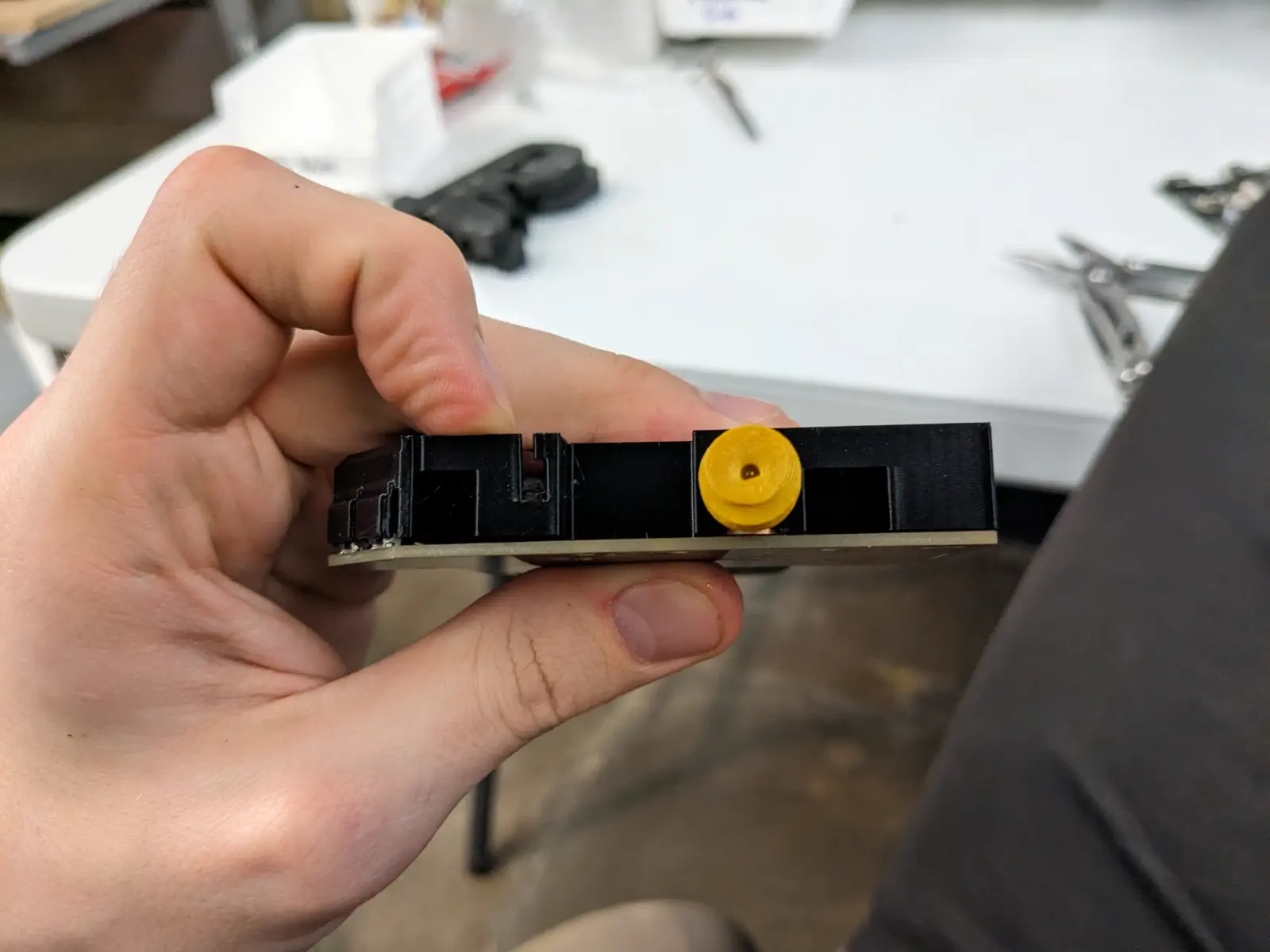
Press the PCB flat into
feeder-frame.- Make sure the cable is not caught between them - it should lay flush.
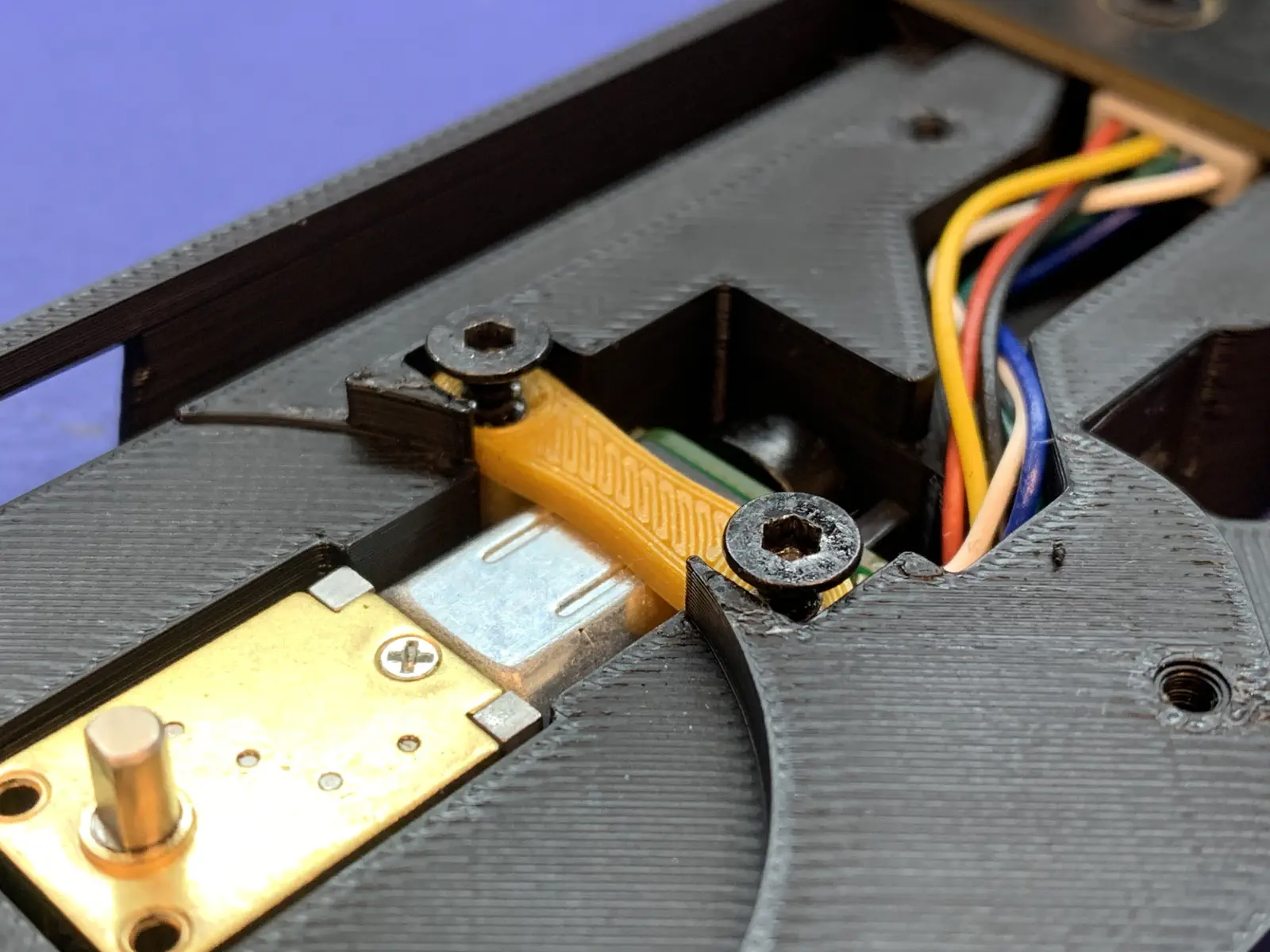
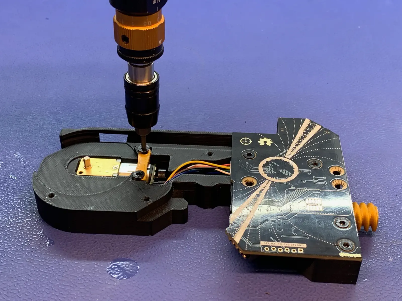
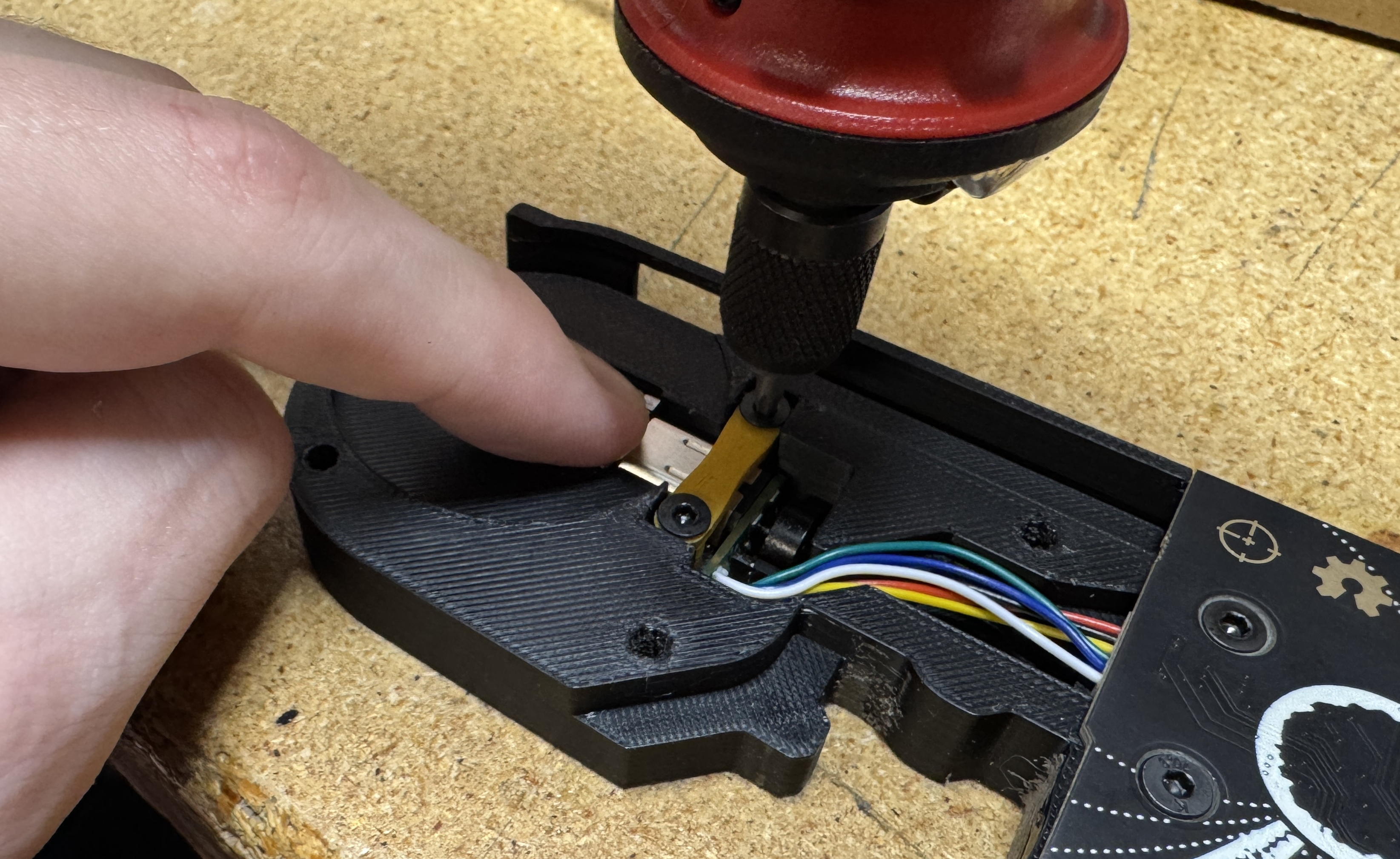
-
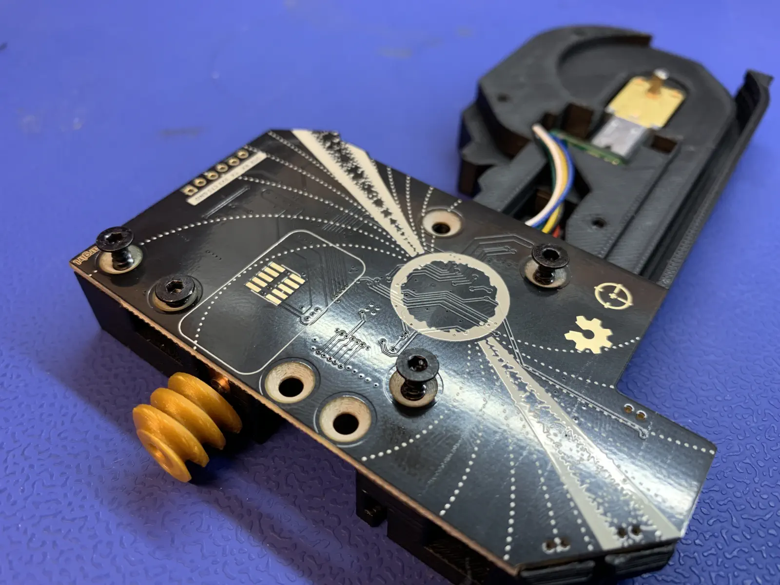
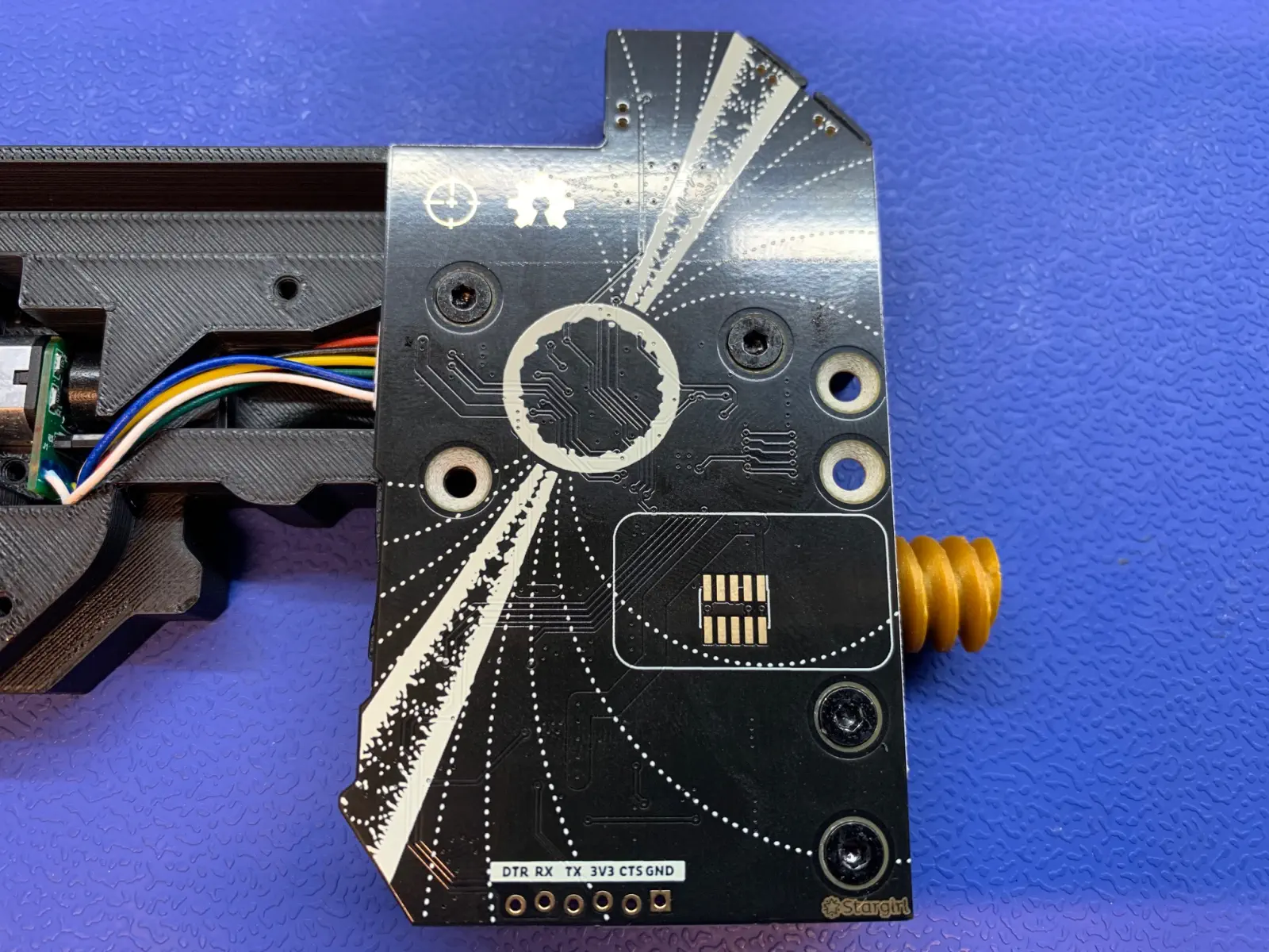
Insert 4x
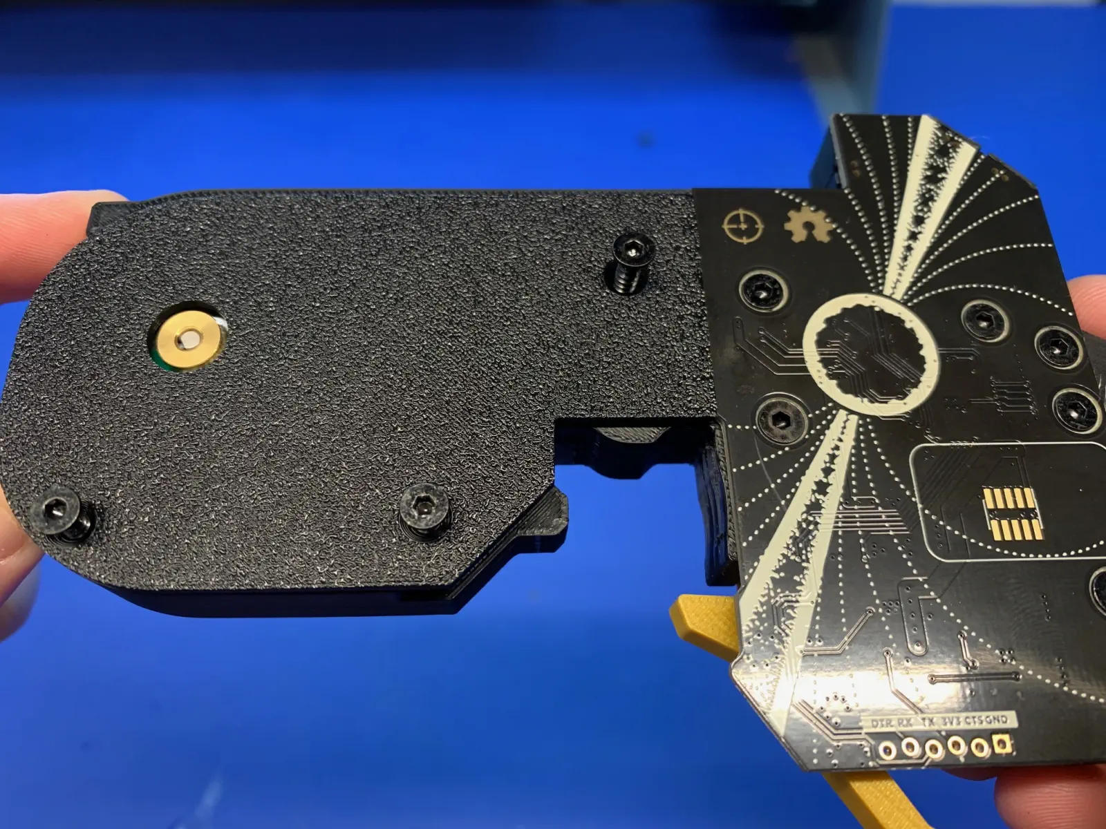
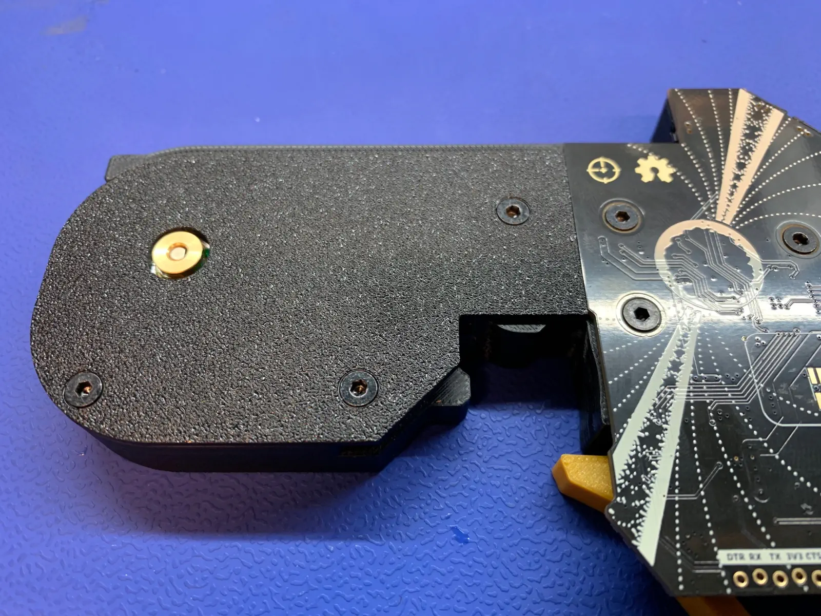
M3x12mmflathead screws into the holes in the PCB as shown below.- Use the torque driver with power set to 5.
- Use the peel worm gear gauge to ensure that the worm gear does not stick too far out from the feeder.
-
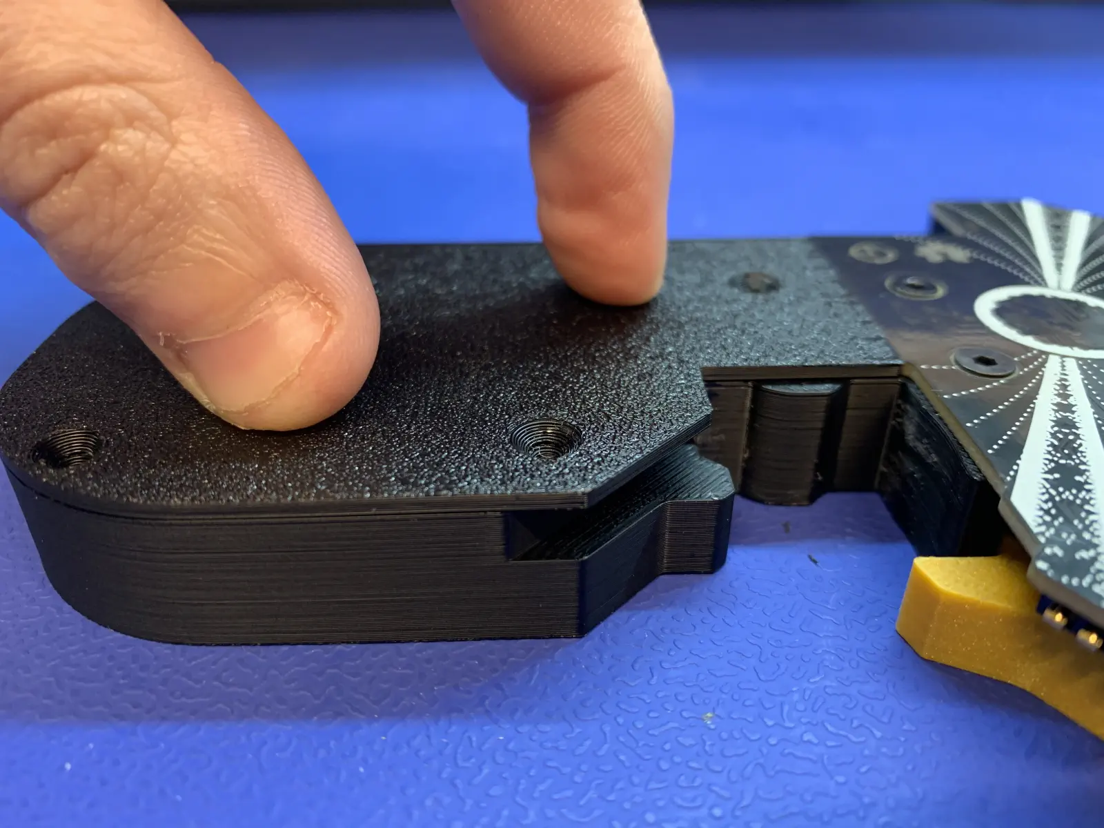
Actuate the buttons to ensure they do not have a mushy feeling.
-
Install a
drive-motor-bracket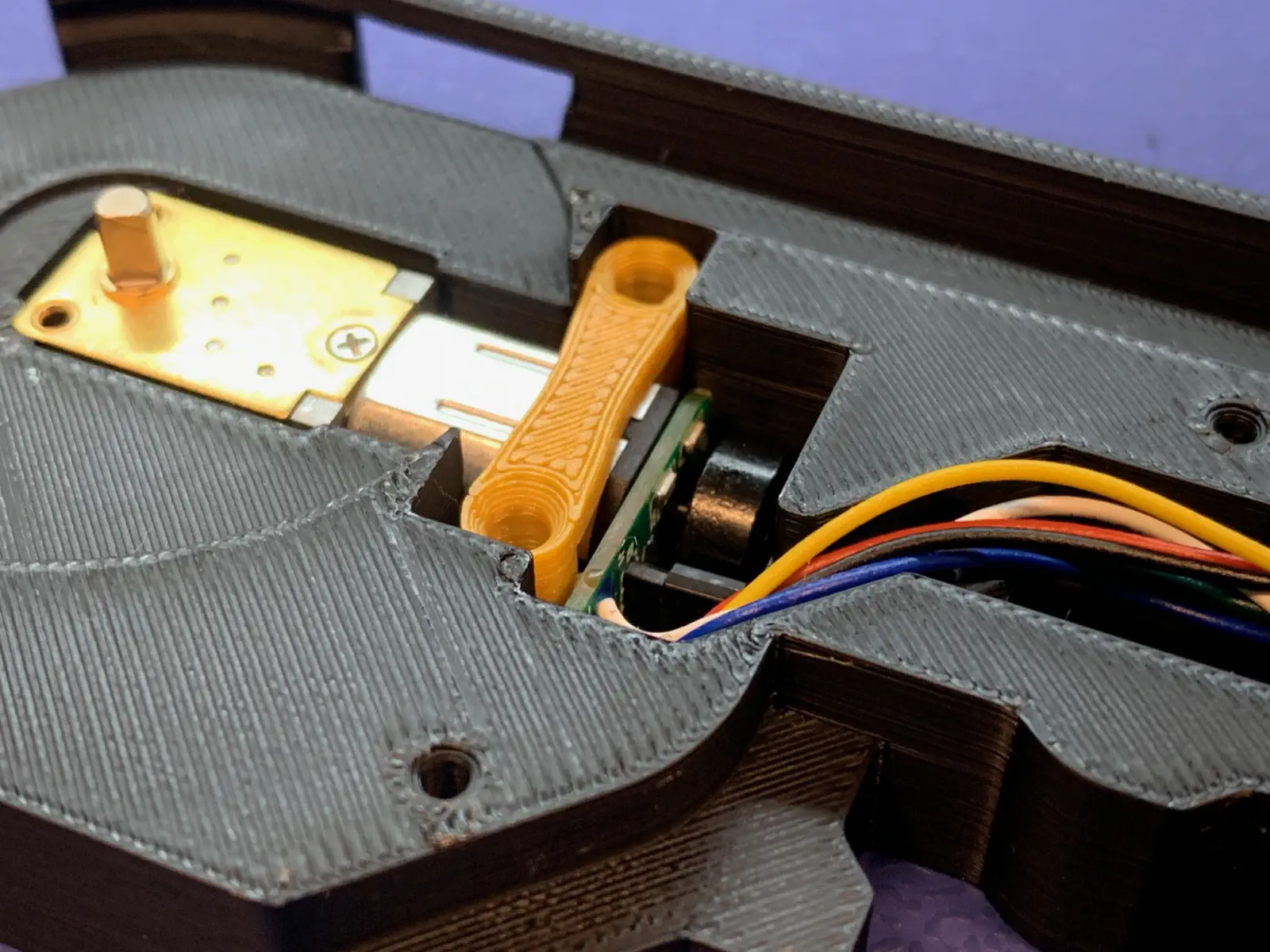
-
Insert 2x
M3x12mmflathead screws- Drive motors have a tendency to lean to the left during installation, so install the first M3X12mm flat head screw in the right side of the bracket while bracing the left side of the bracket.
- Install the second screw while bracing the right side of the drive motor.
- Gently press on the back side of the drive motor. The motor should move back to its original position and remain flush to the back of the feeder.
DO NOT OVER-TIGHTEN
Over-tightening can lead to bracket damage and motor skewing in the
feeder-frame-8mm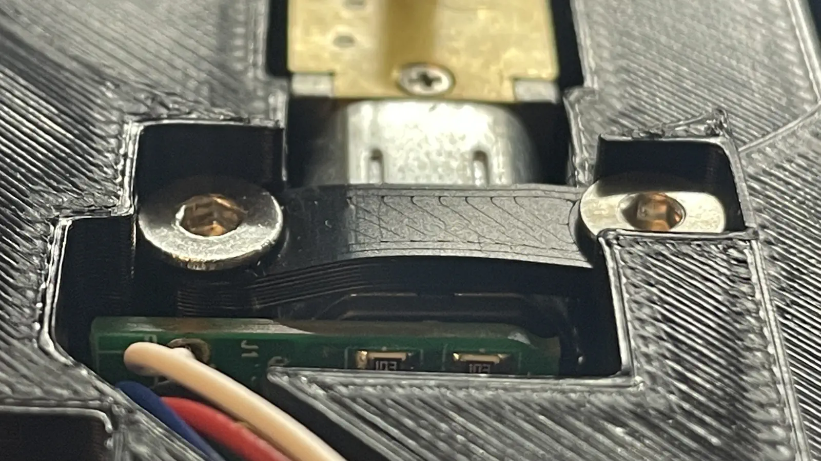
DO NOT UNDER-TIGHTEN
Undertightening can result in the motor being loose in the cavity.
-
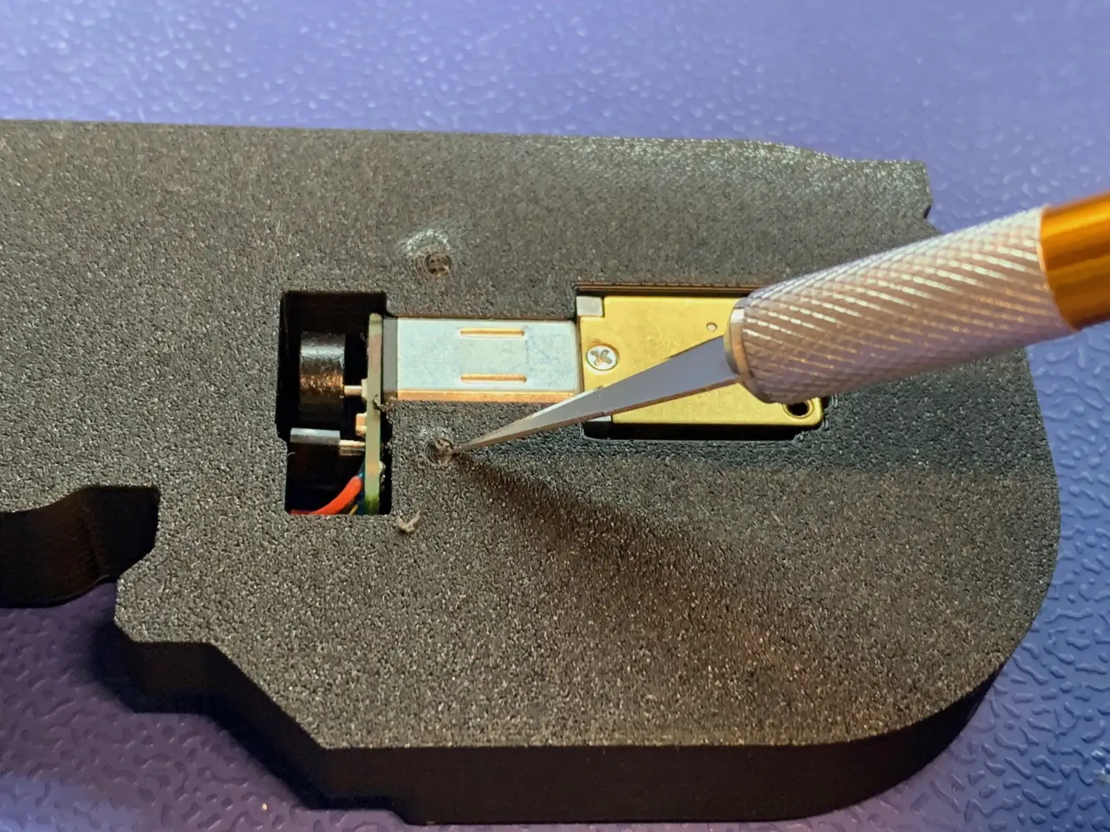
Use an X-Acto knife to remove the filament from the bracket screws.
- This will ensure that the feeder sticker can properly adhere.

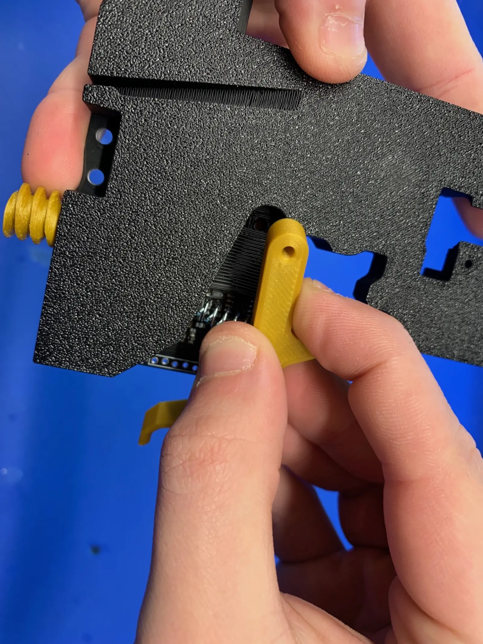
Install the release-lever
Wearing safety glasses is required while installing springs
-
Install the spring
-
Hold a spring against a release lever as shown:
-
Match the other end of the spring up with the circular cutout in the
feeder-frame-8mmprint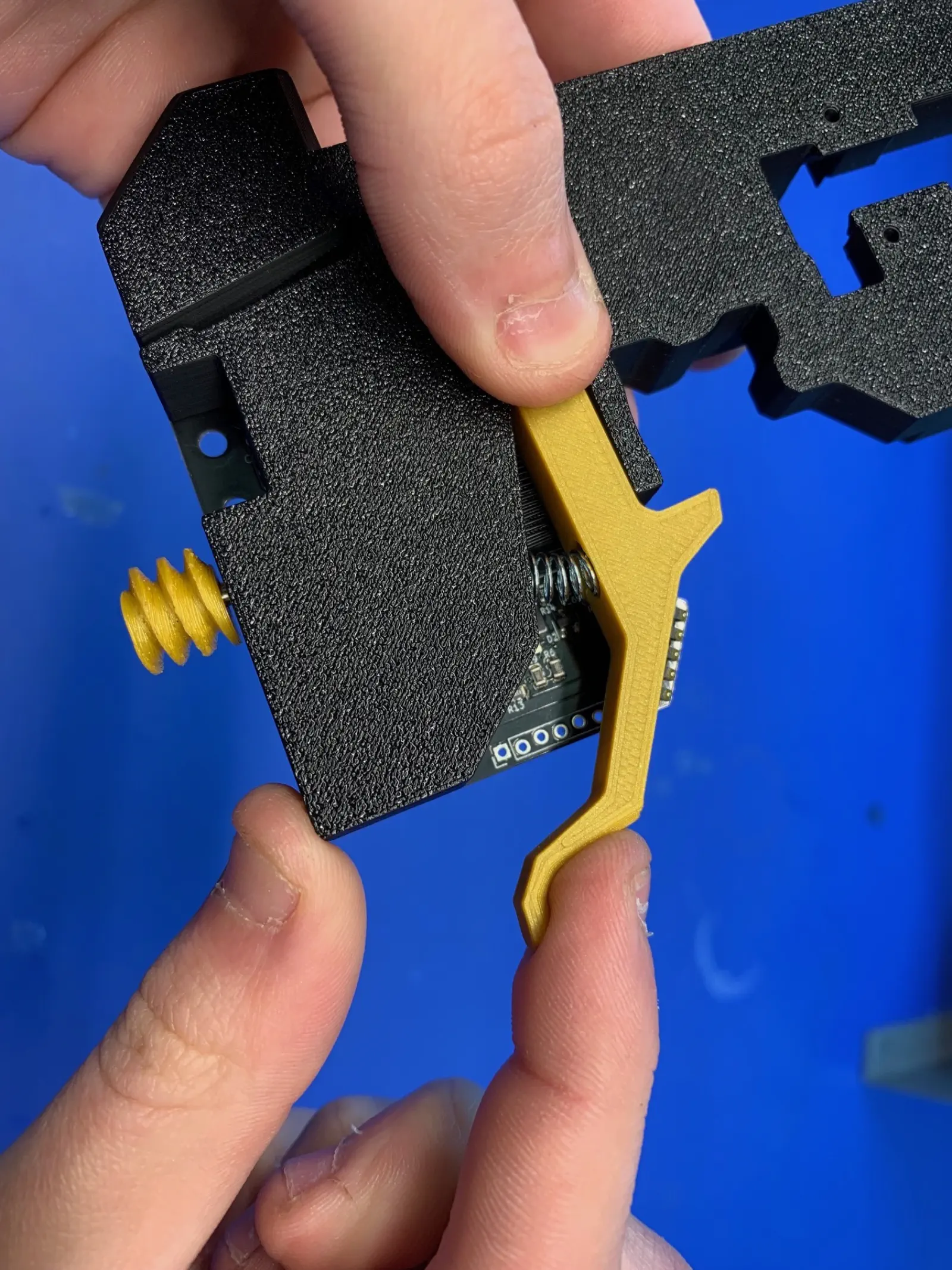
- Press the release lever into the space on the feeder.
-
-
While maintaining pressure on the back of the release lever, install a M3X15mm screw.
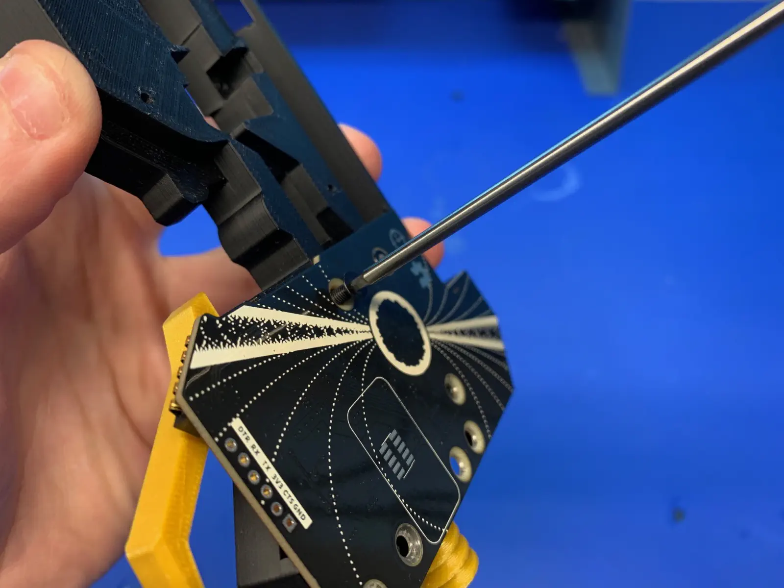
- Once installed, the release lever has no lateral movement and can swivel easily with a snappy motion.
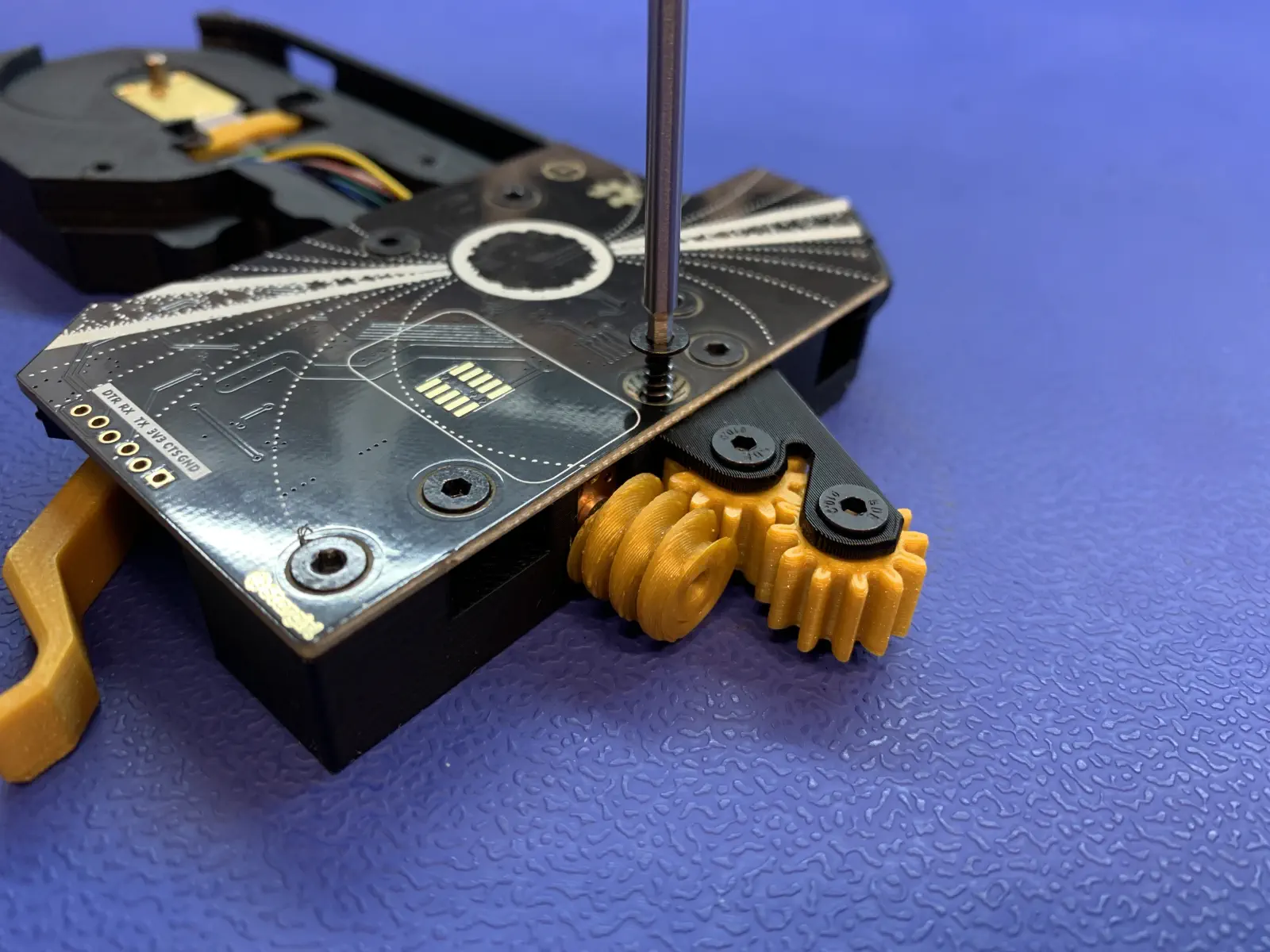
Install the peel-gear-box
-
Obtain
peel-gear-box.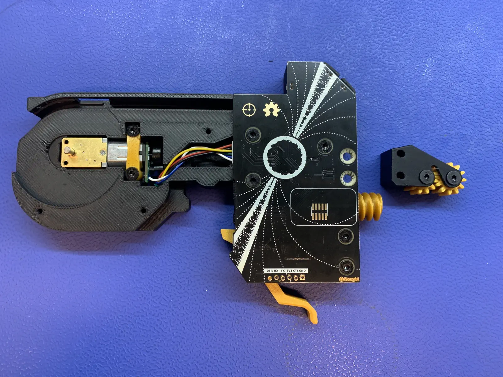
-
Place the peel gear box in place, engaging with the worm gear in the peel motor assembly.
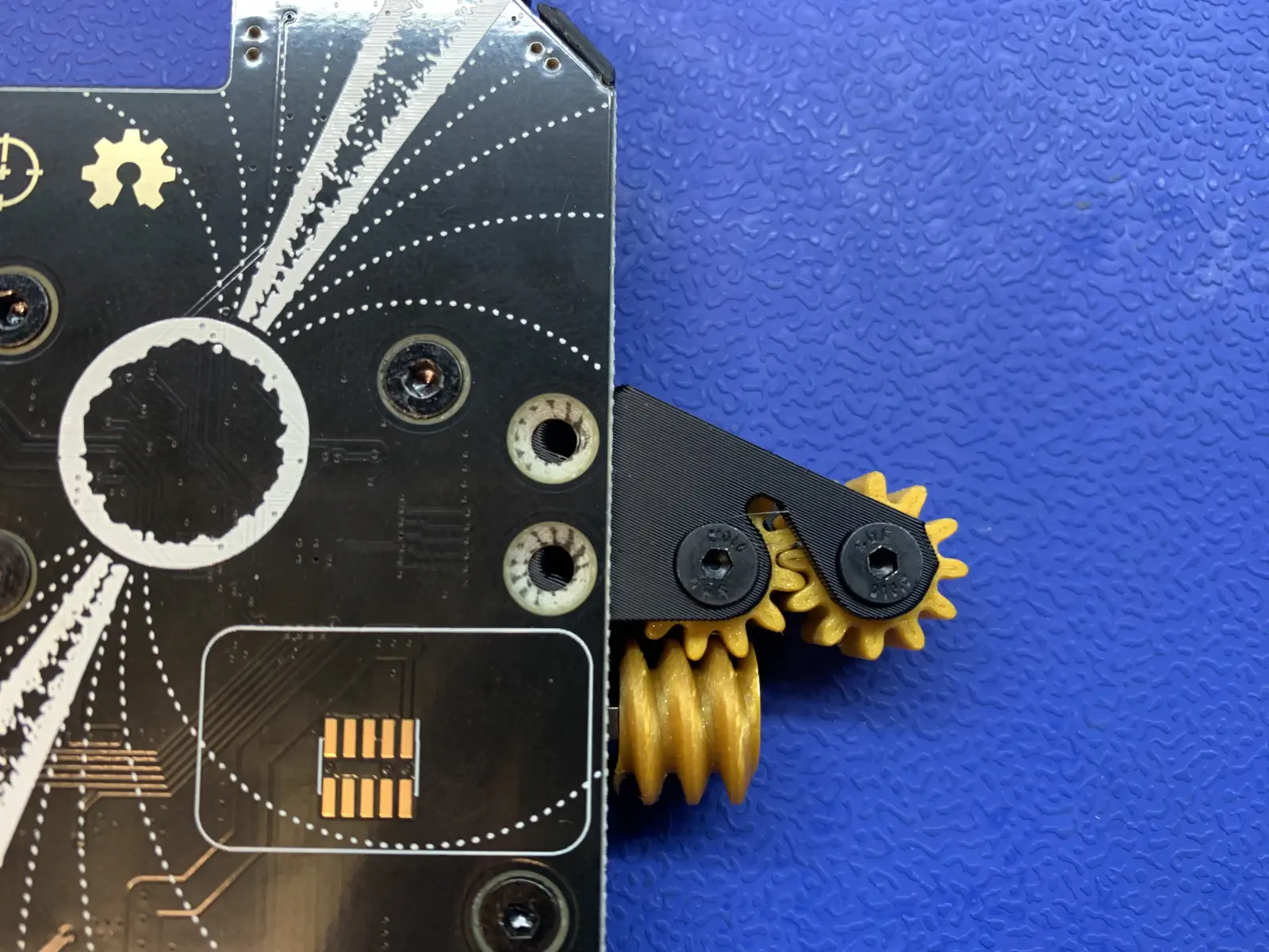
-
Install 2x M3x12mm flathead screws in the locations shown:
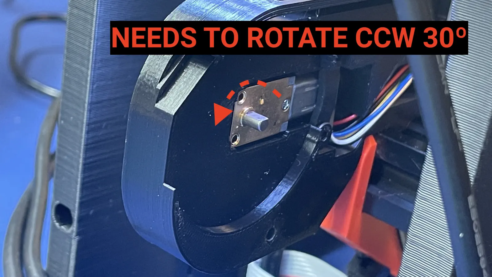
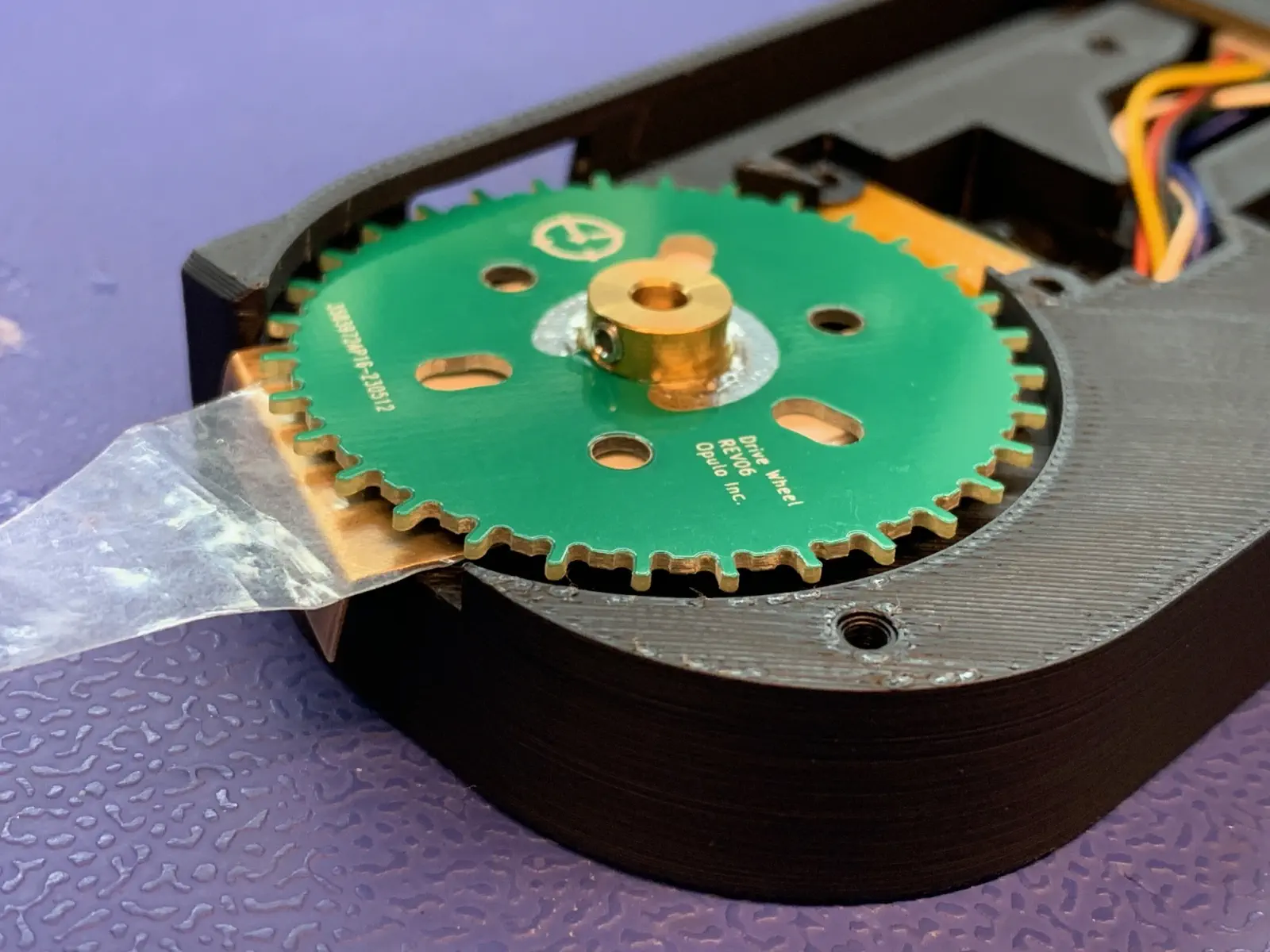
Install the drive-wheel-asm
-
If necessary, rotate the drive motor so the flat surface of the shaft faces the front of the feeder.
-
Place the drive wheel shims in the wheel cavity as shown:
-
Place the drive wheel on the shaft as shown, with the set screw aligned with the flat surface of the shaft.
-
Maintain pressure on the top of the drive wheel while tightening the set screw.
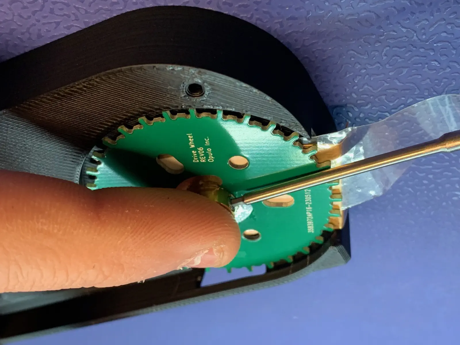
- Use a handheld torque driver with 1.27mm bit set to 30 cN.m.
-
Remove the drive wheel shims.
-
Place the feeder on the jig and drive the wheel at least one full rotation, listening for friction. If friction is heard, replace the wheel. If there is obvious wobble in the wheel, replace the wheel or reattempt installation.
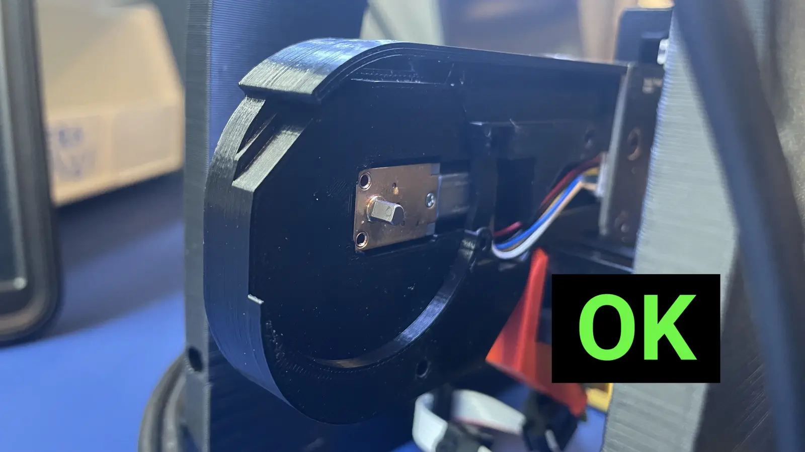
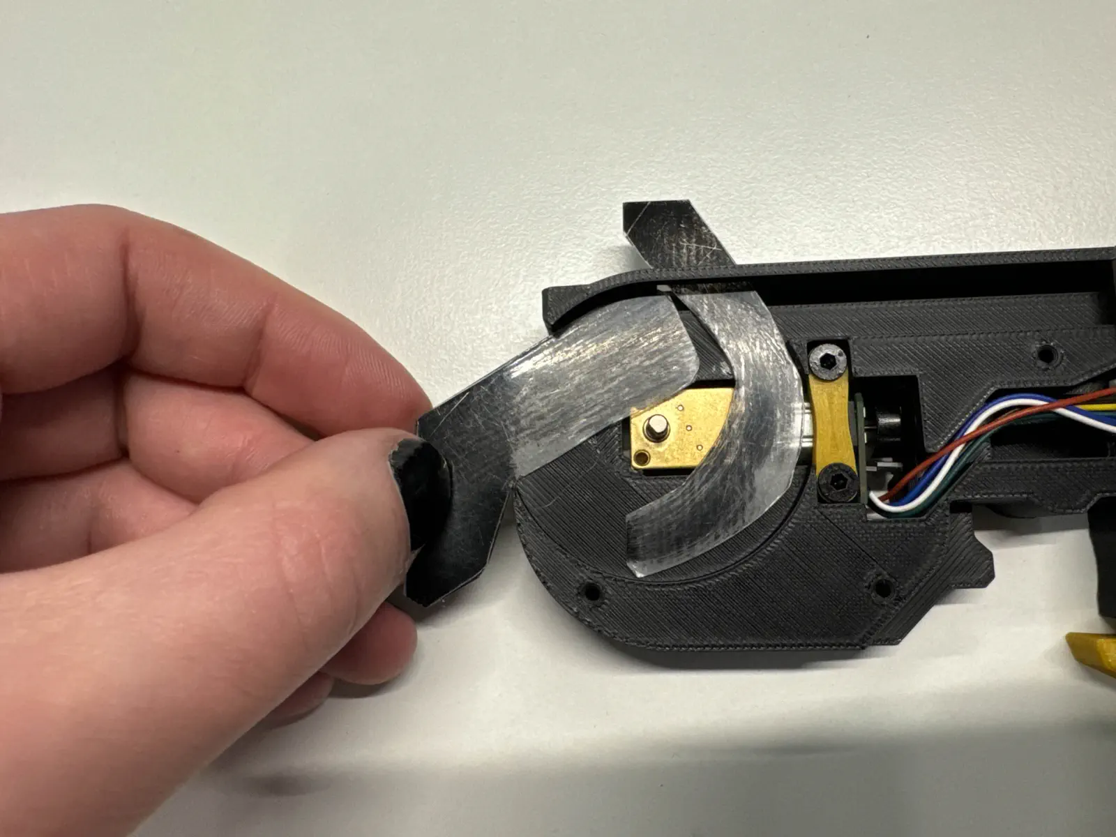
Install drive-motor-cover
-
Place a drive motor cover over the drive wheel.
- The cover should be flush, with the drive motor cables being tucked into the channel.
-
Insert 3x
M3x12mmflathead screws in the locations shown below- Use automatic screwdriver set to 5
You may now proceed to OQC