8mm/12mm Feeder Frame Assembly
This section will guide the reader through the process of installing various hardware components into feeder-frame-8mm or feeder-frame-12mm in preparation for its use in final assembly.
Materials Needed
- Frame print
- X-Acto knife
- Needle-nose pliers
- Loctite 435 super glue
- Light diffuser PCB
- 8mm fiducial board or 12mm fiducial board
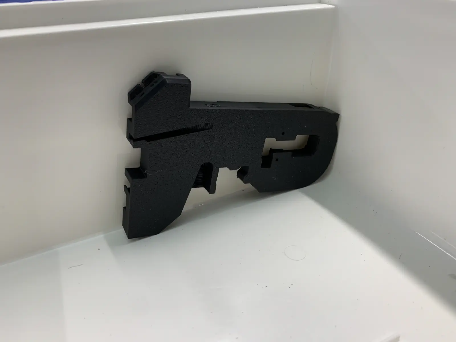
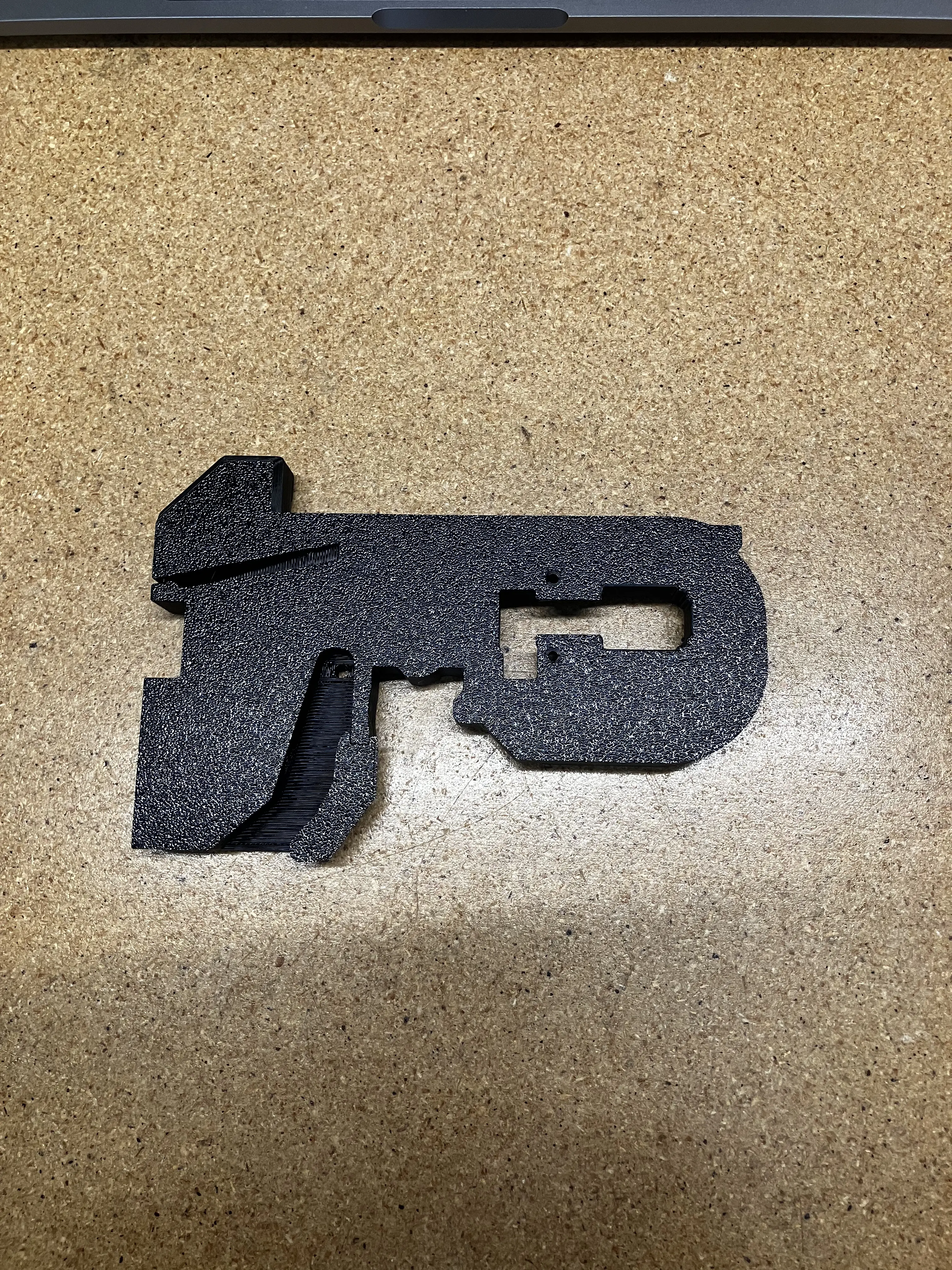
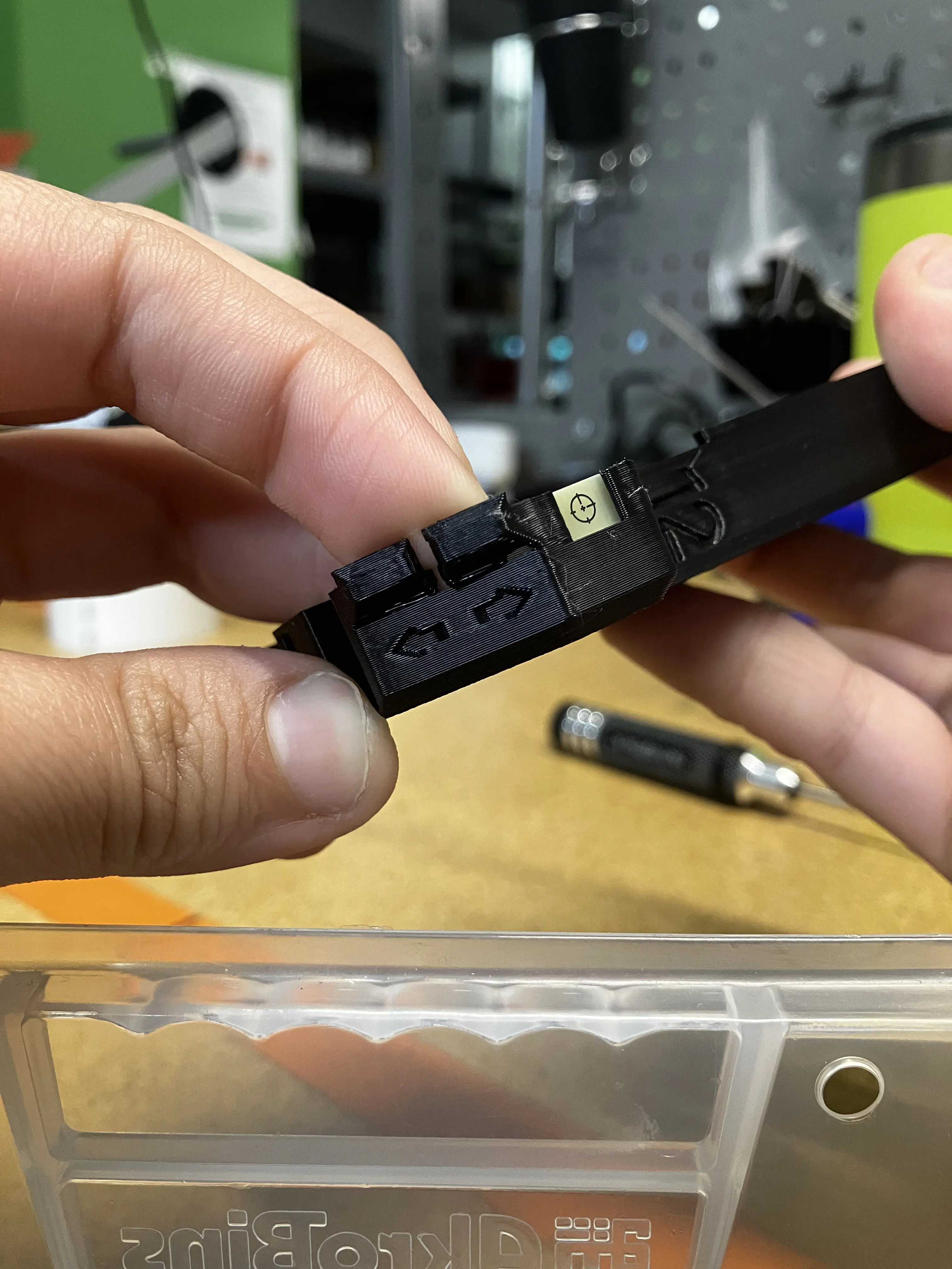
Prepare Print
-
Inspect the print for defects.
- All surfaces should be free of excess filament and be relatively flat
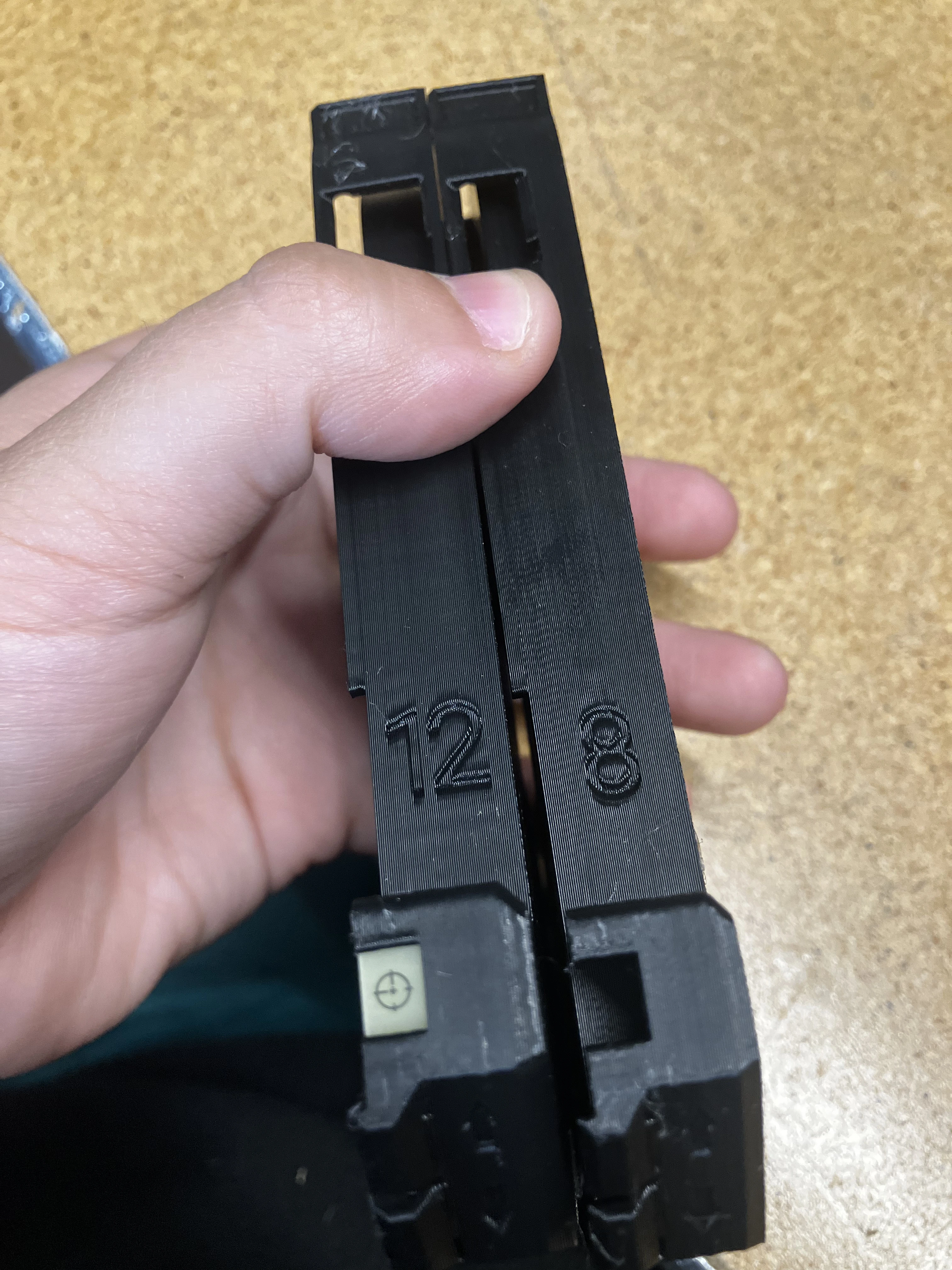
- Ensure you are working with the correct feeder frame, either 8mm or 12mm.
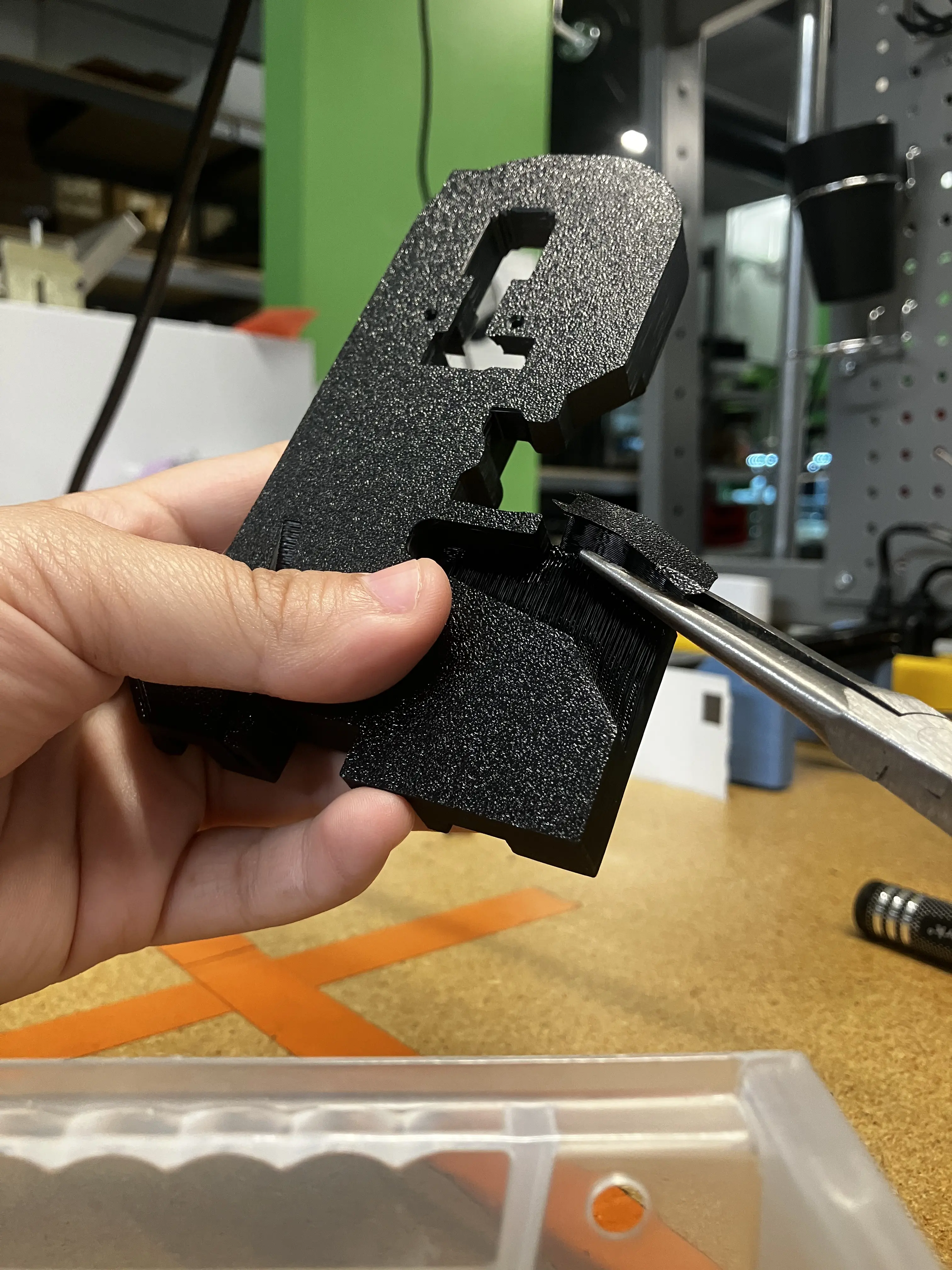
-
Remove the support from the frame with needle-nose pliers.
- The support may leave behind extra filament that will prevent proper actuation of the release lever. Remove this with an X-Acto knife
-
Use needle-nose pliers to gently pry the buttons from their support. Do not use too much force as this may cause the buttons to break off.
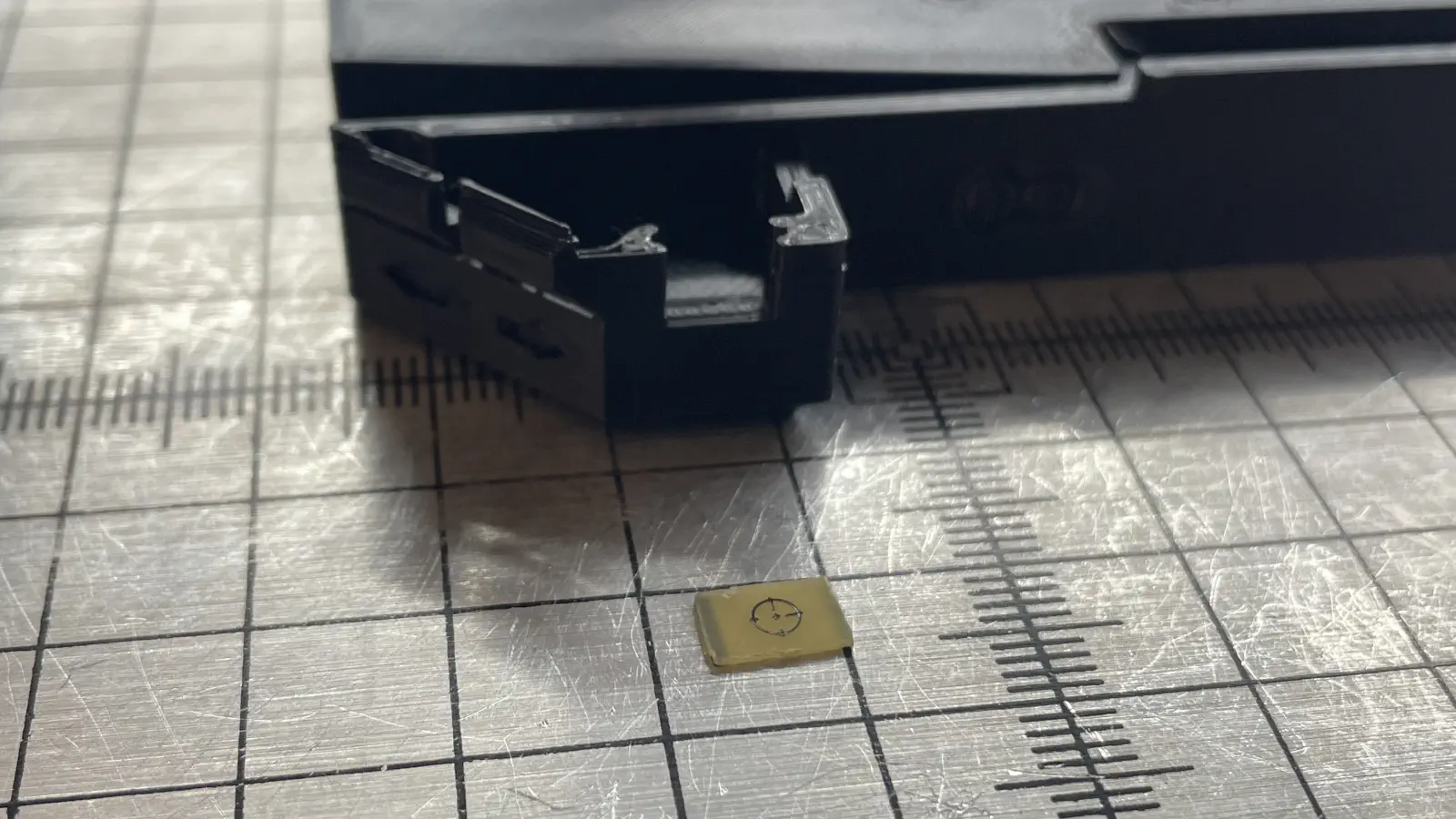
Install Light Diffuser
-
Use needle-nose pliers to install the light diffuser PCB.
-
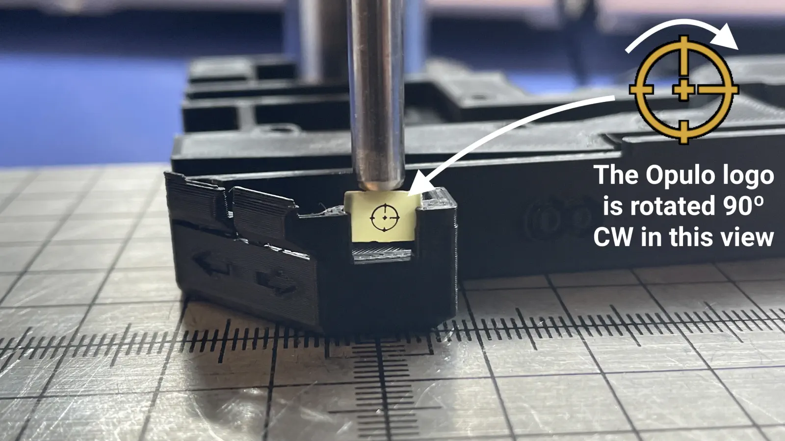
The Opulo logo on the PCB should be oriented as such:
-
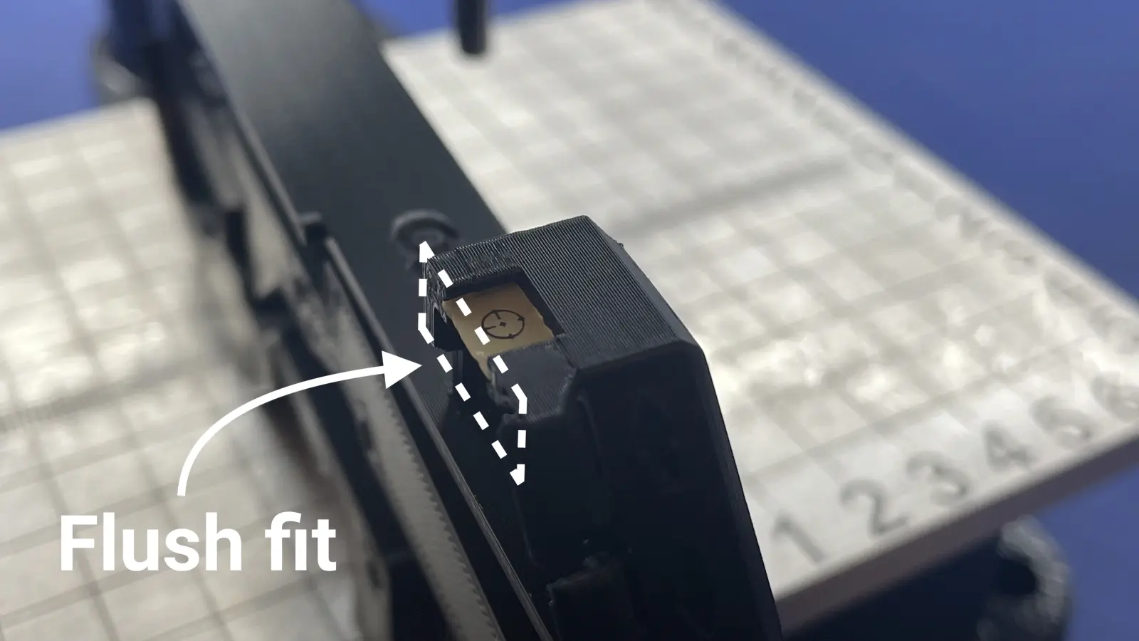
The installed PCB should be flush with the feeder frame.
-
Install Fiducial Board
Hold it Partner
It is important to be aware that the fiducial for the 8mm & 12mm frames are slightly different.
- Be aware what frames you are working with
- Be aware what fiducials you are gluing
-
Dispense a small amount of Loctite 435 in the front pocket of the feeder frame.
-
Place the fiducial board in the pocket with the fiducial markers facing upward.
-
Orient frame upright for at least 30 minutes before proceeding with assembly.