Feeder Connection Kit
This section will guide the reader on how to properly prepare the accessories that go into a feeder-connection-kit.
bagged-extrusion-cable-clips
-
Place 10x
extrusion-cable-clippieces into a3x4-bagbefore sealing it shut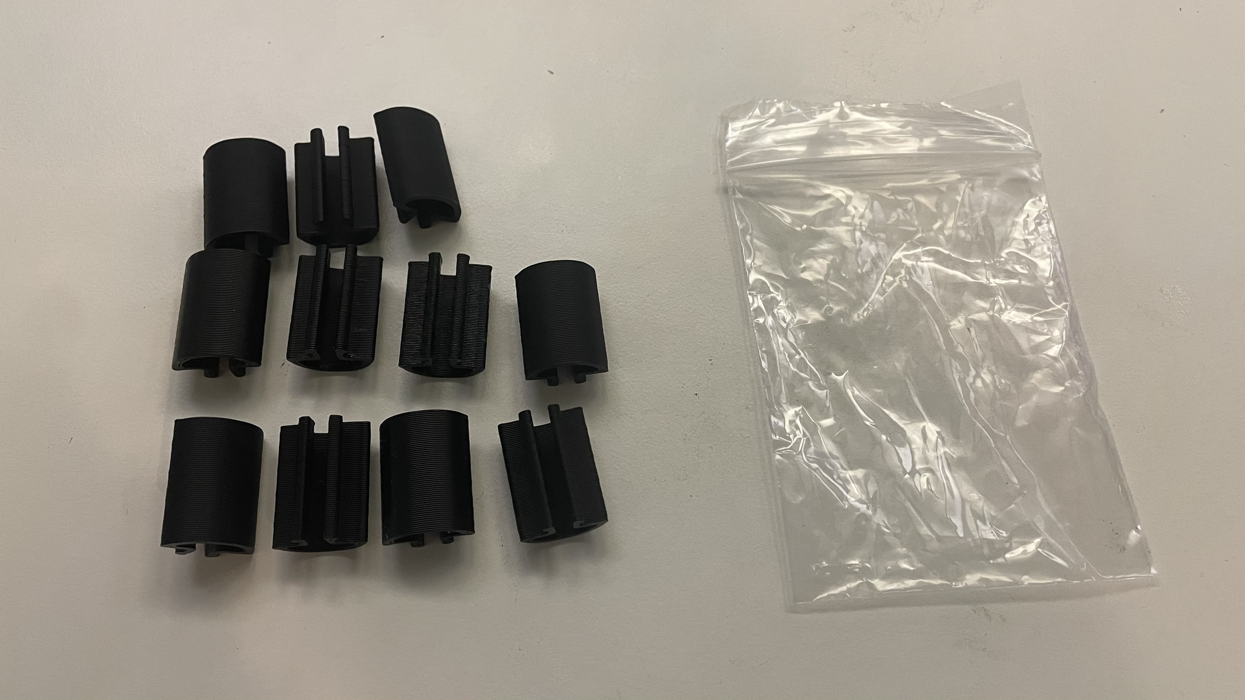

-
Place each
bagged-extrusion-cable-clipsset into a yellow NEEDS QC bin while it awaits inspection
-
Weigh each
bagged-extrusion-cable-clips, confirming it weighs19.9g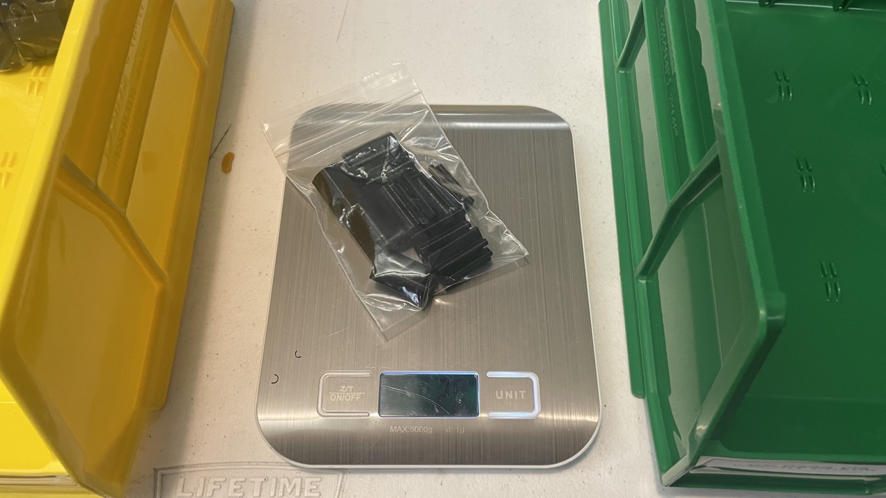
-
Place the
bagged-extrusion-cable-clipspieces that pass weight check into a green QC-Pass bin
Hex Key for Drive Wheel Adjustment
-
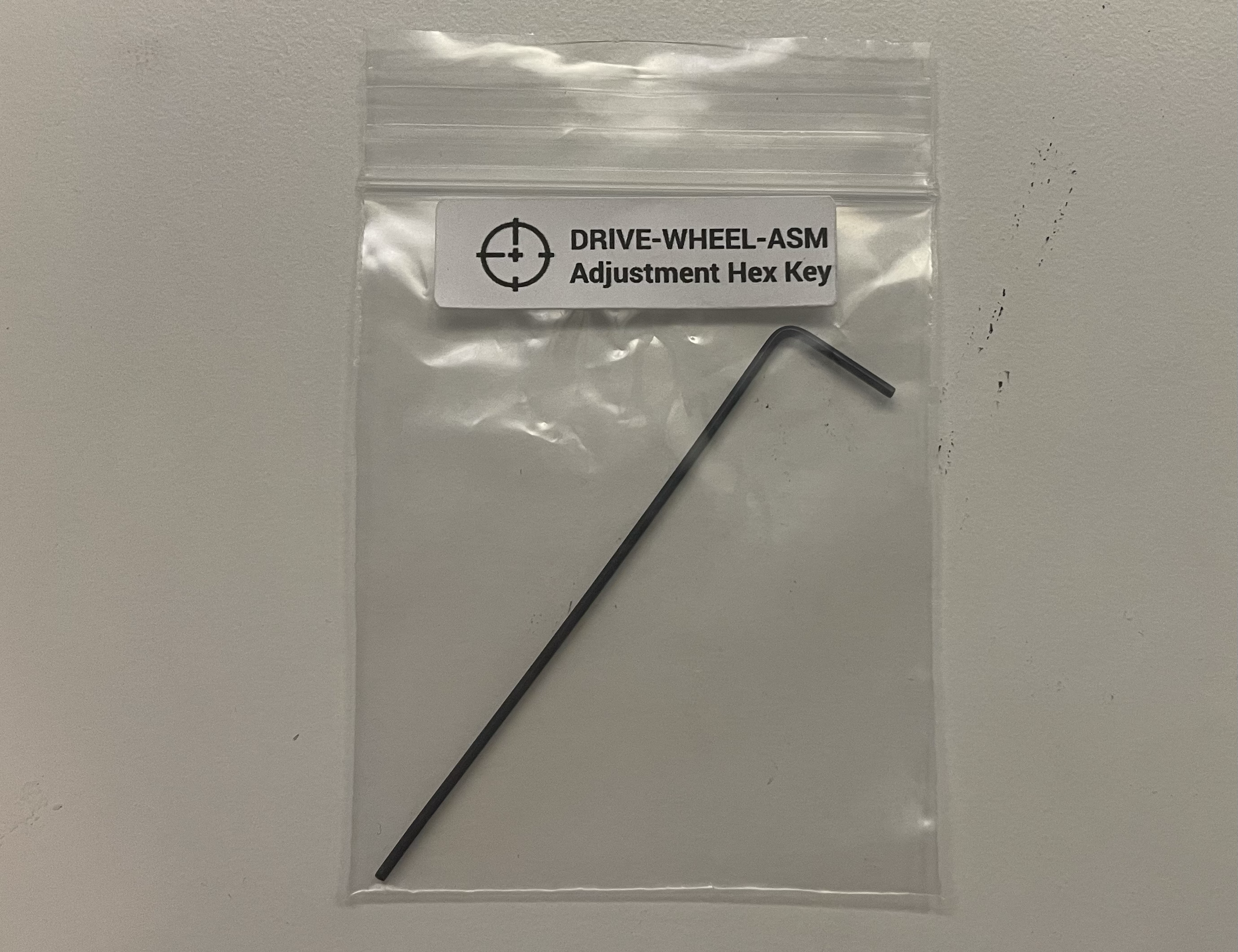
Adhere a "hex key bag label" onto a
2x3-bag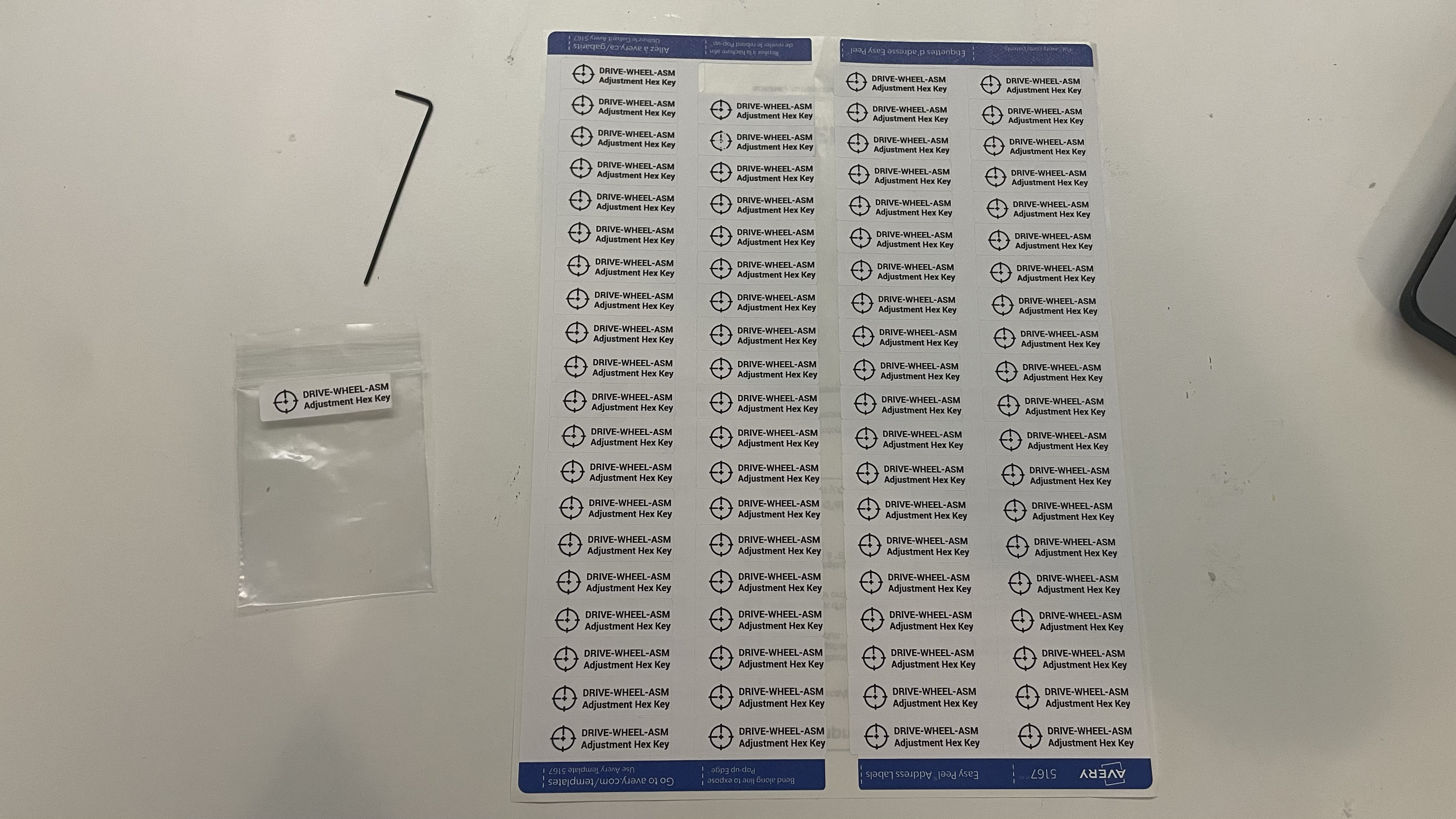
-
Place a hex key into the plastic bag before resealing it
Collect feeder-blade-harness-set
-
Collect a
feeder-blade-harness-set[ASM-0079-02] from inventory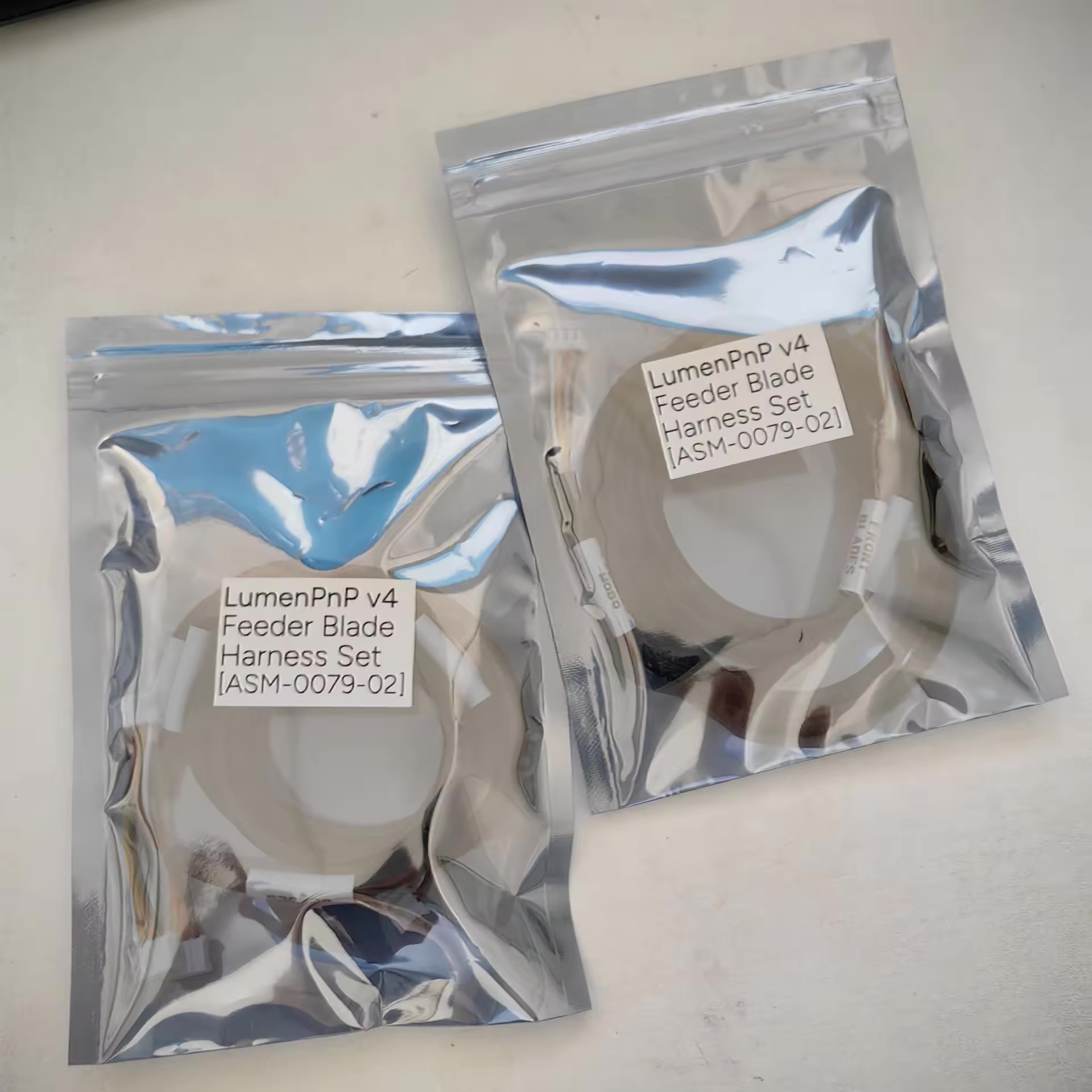
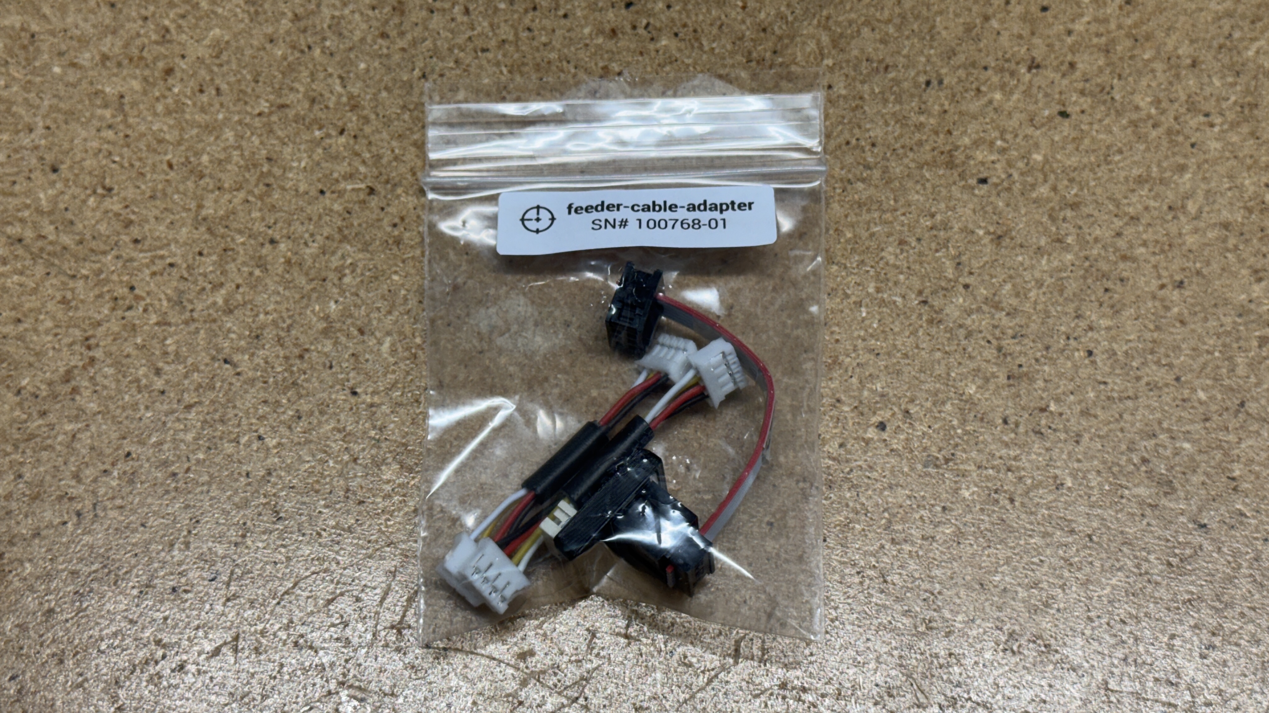
Feeder-cable-adapter
Assemble feeder-cable-adapter
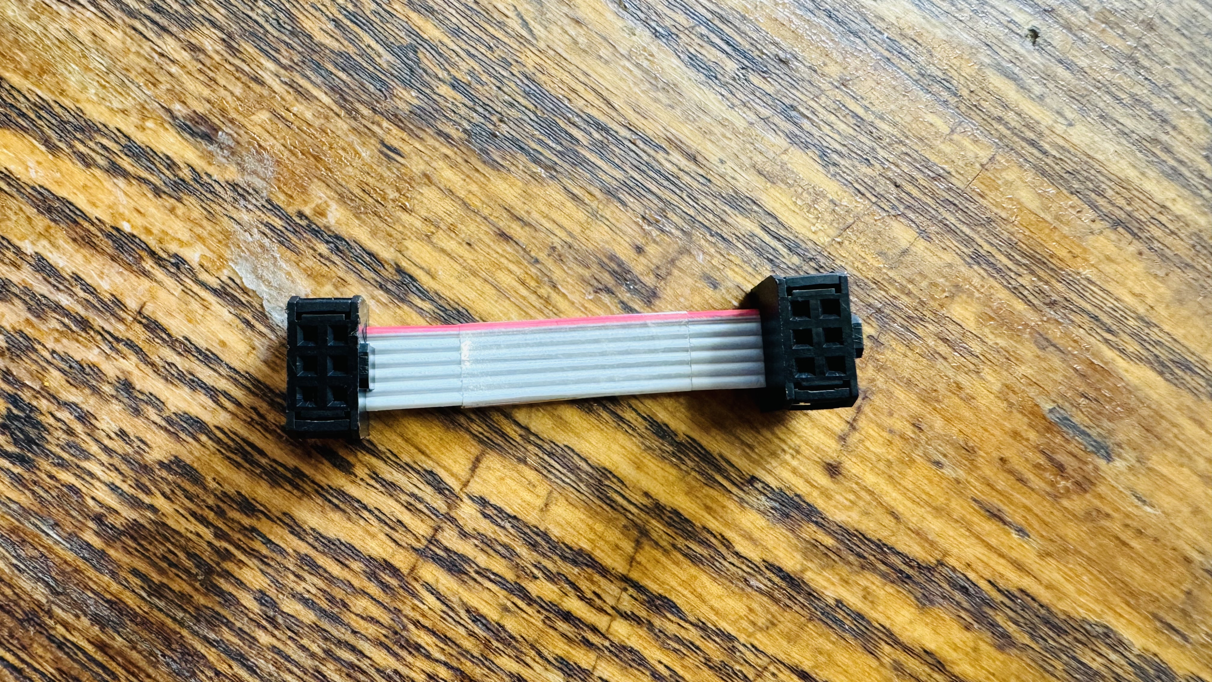
- Create a
50mm-idc-ribbon-cablethat matches the image below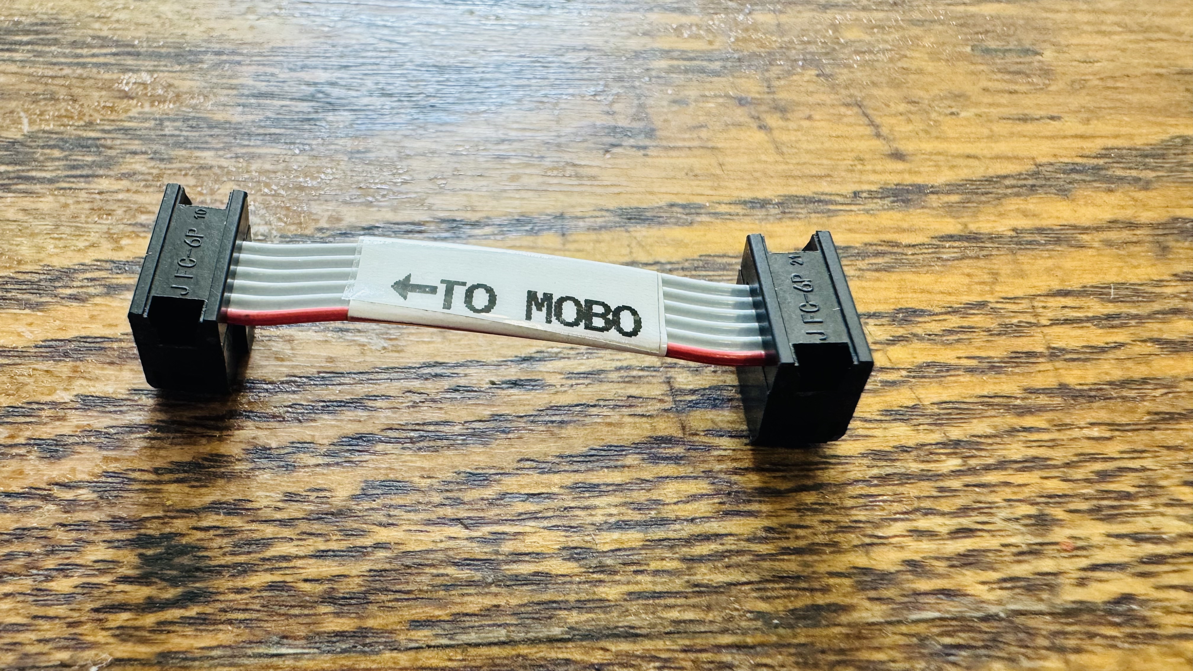
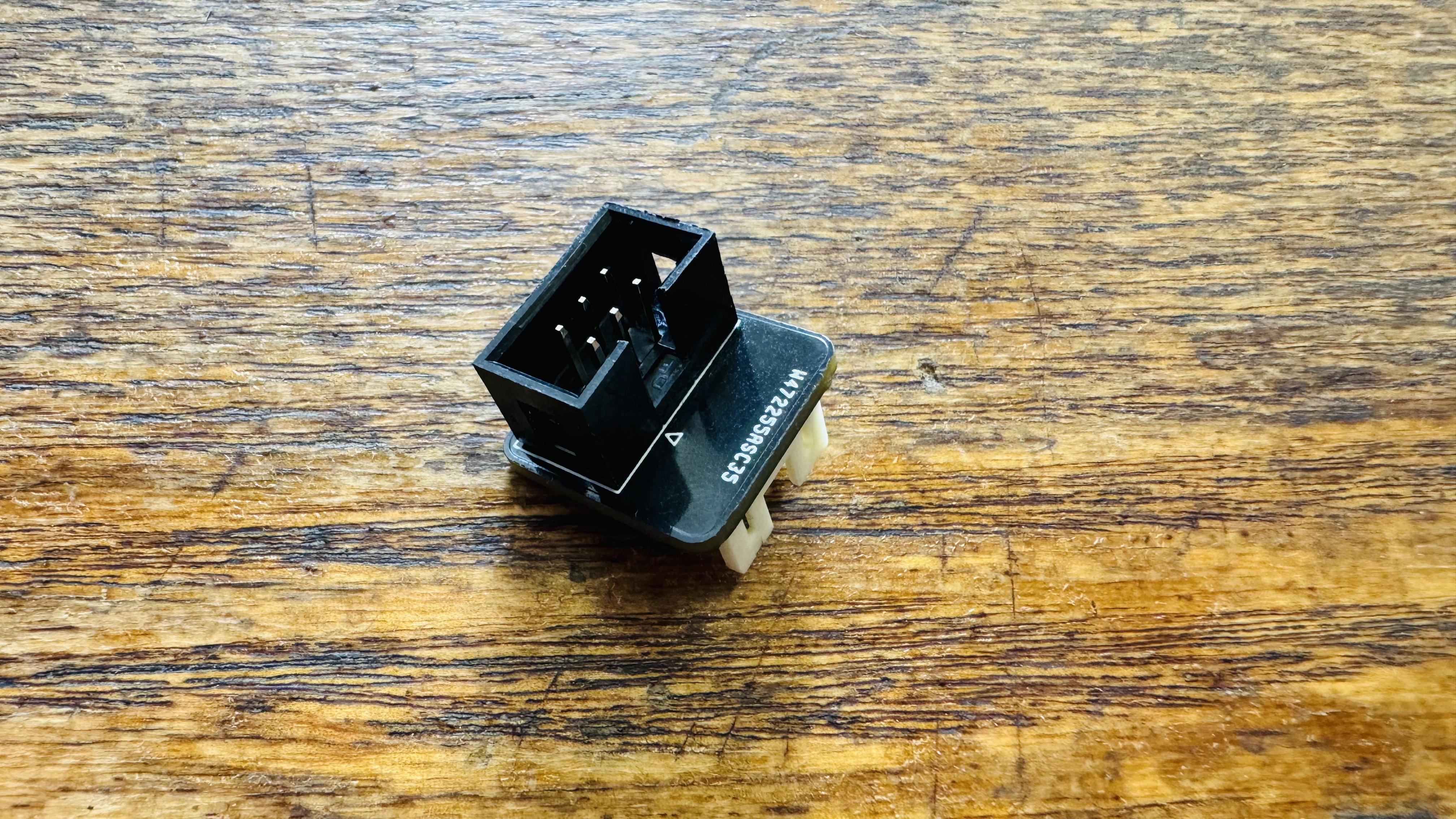
- Assemble
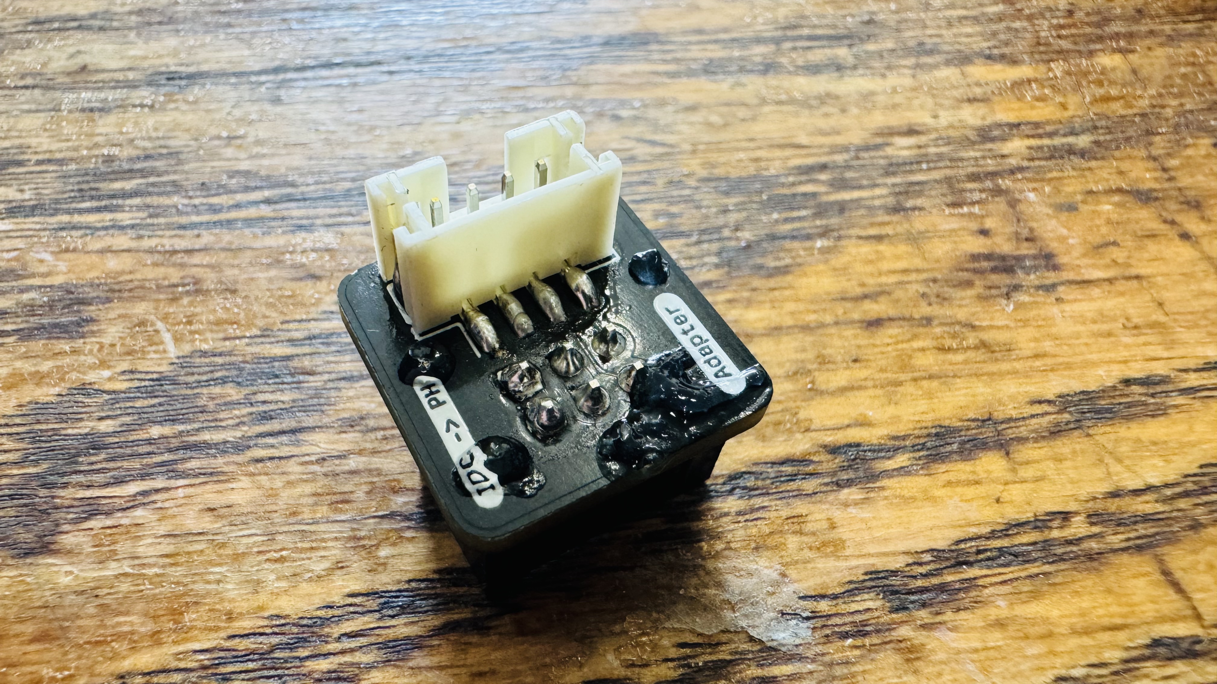
feeder-blade-idc-adapter-pcba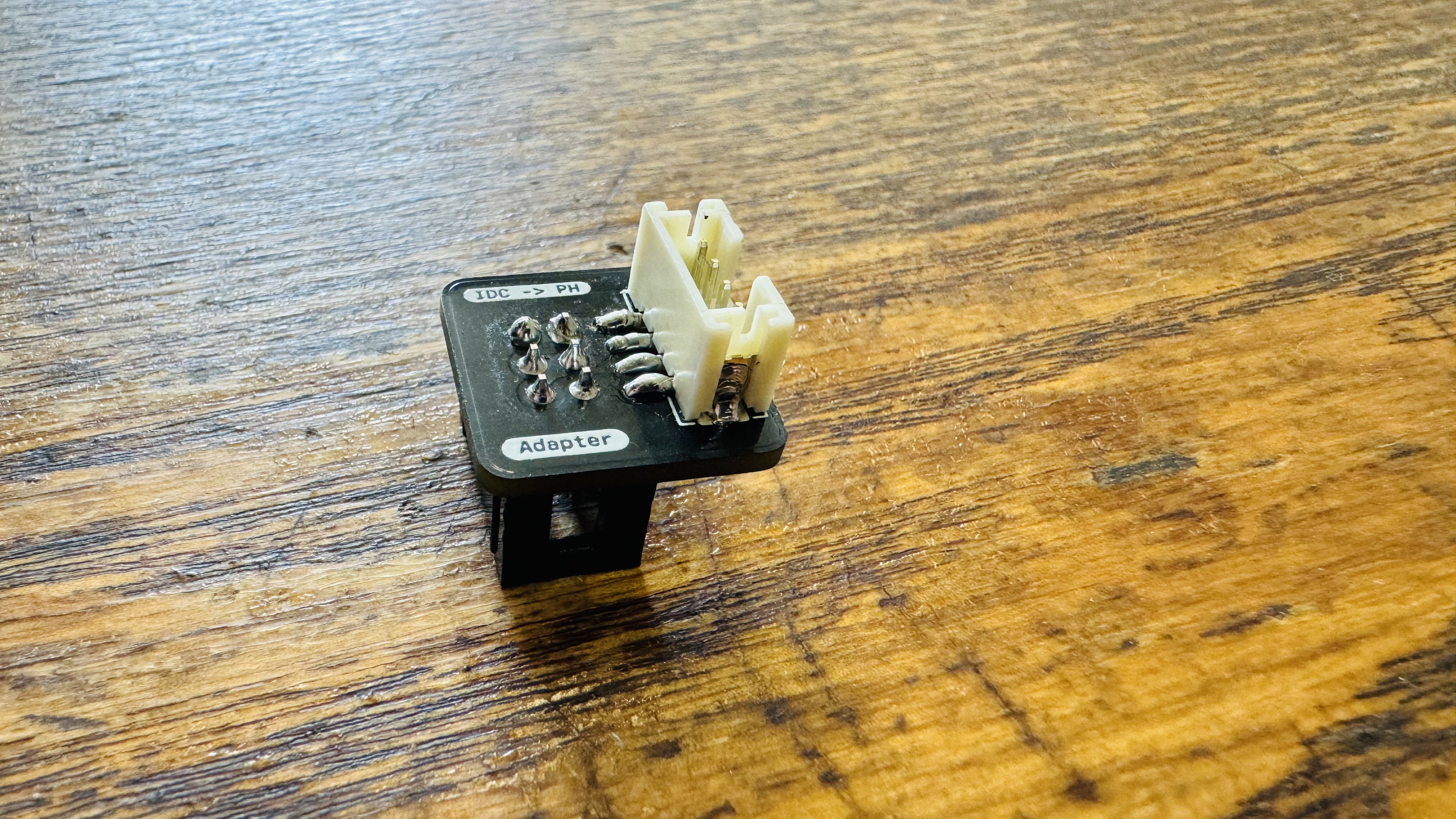
-
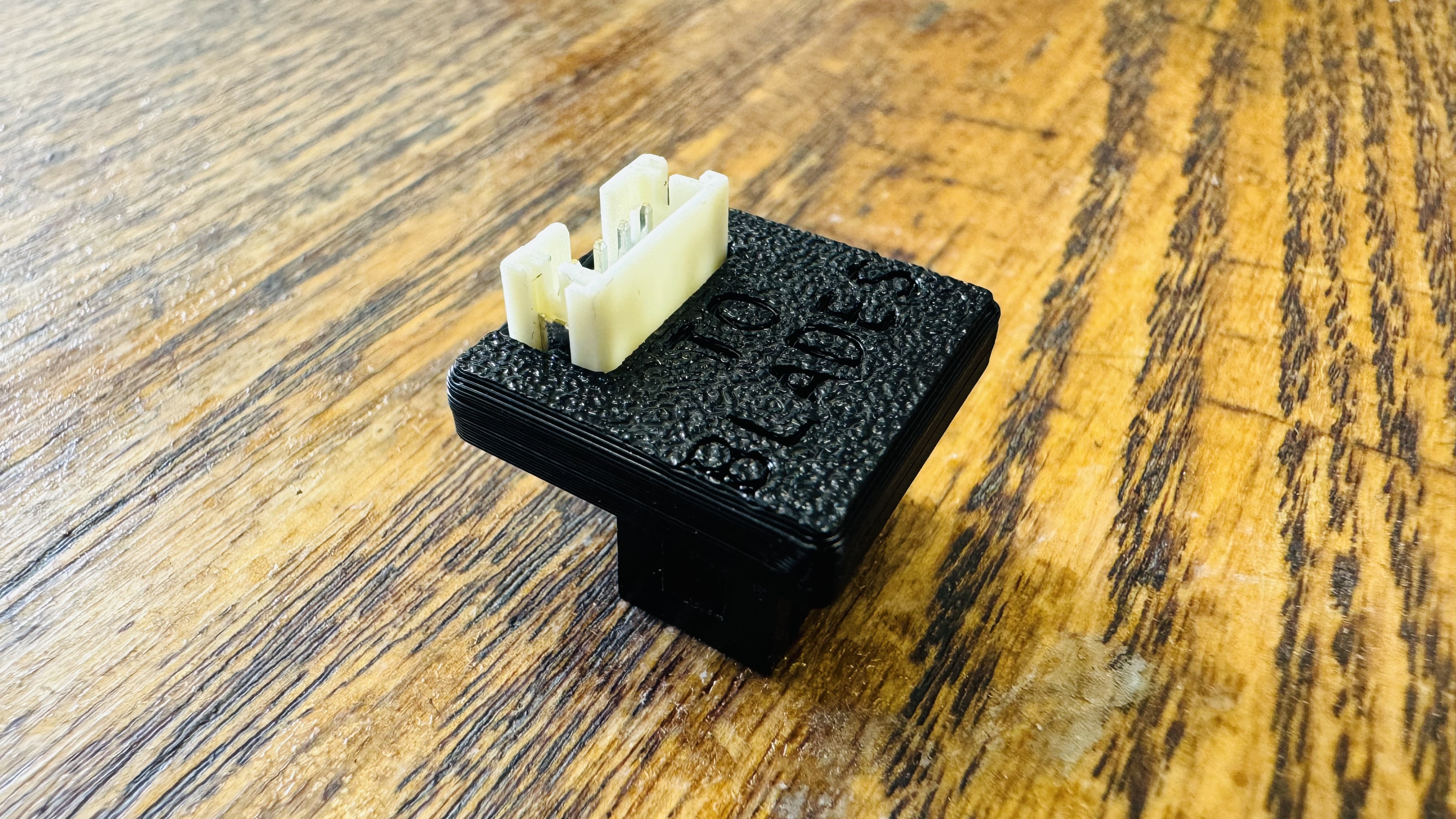
Glue
blade-adapter-pin-coveronto the PCBA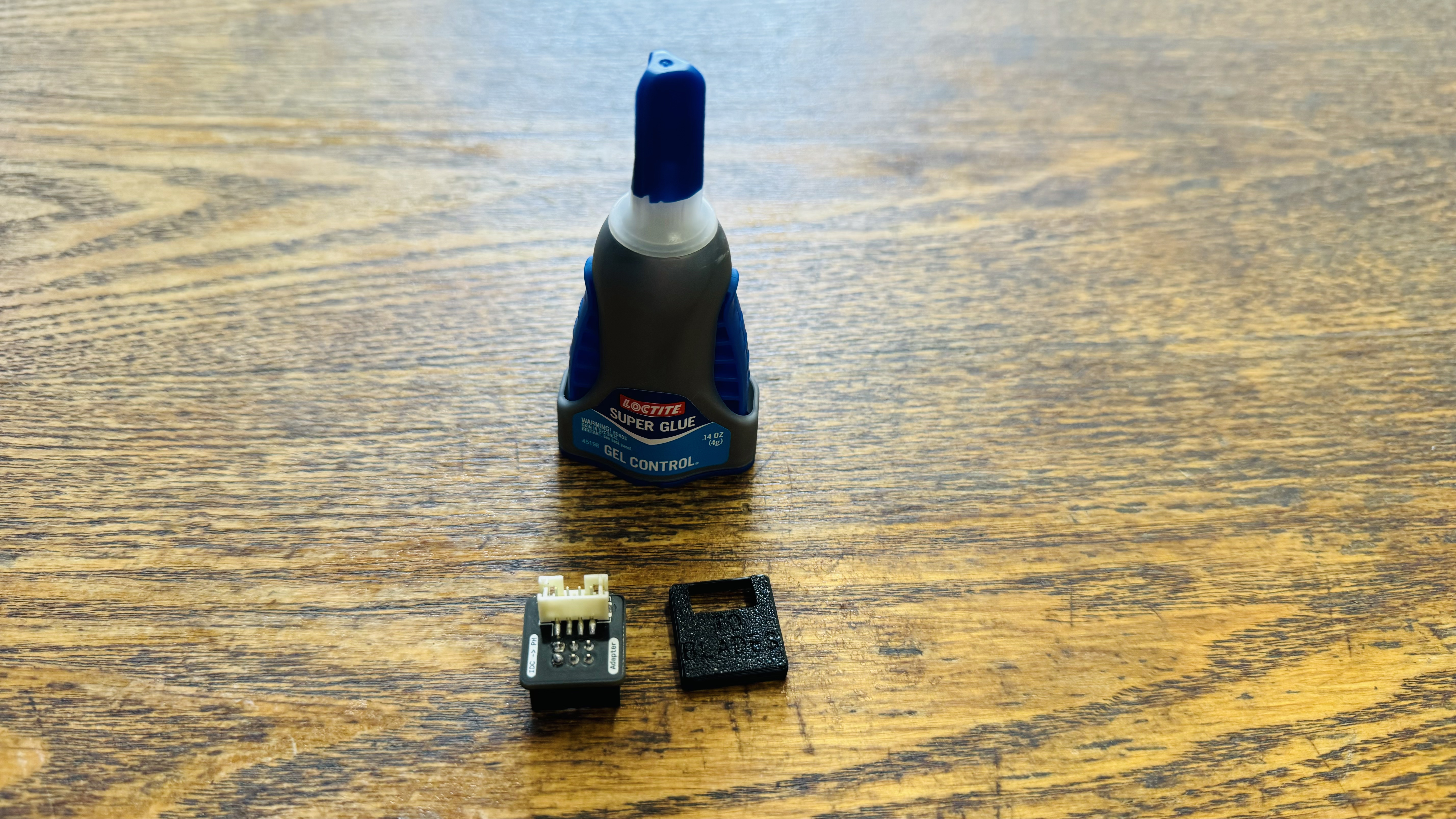
-
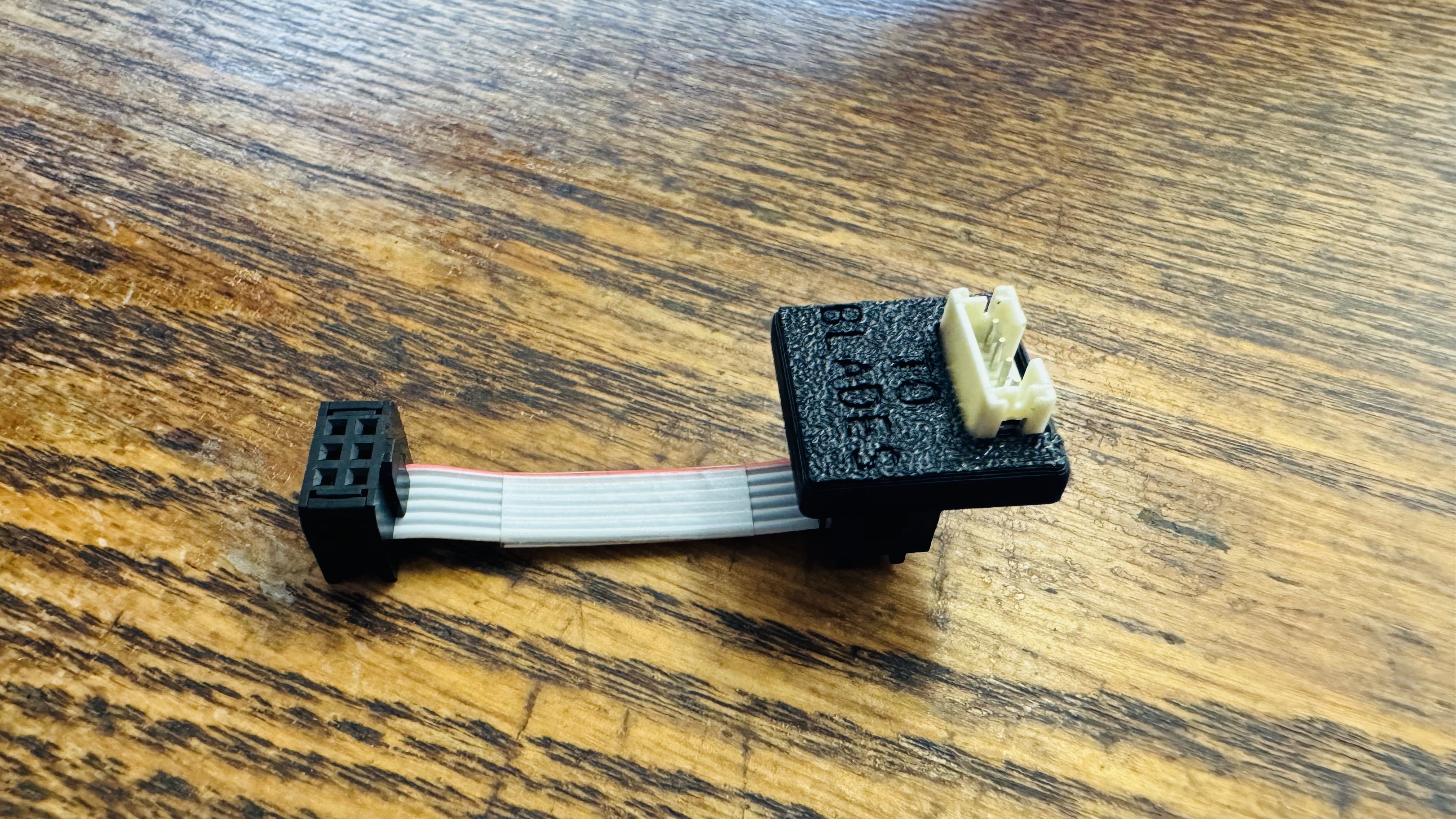
Connect
50mm-idc-ribbon-cabletofeeder-blade-idc-adapter-pcba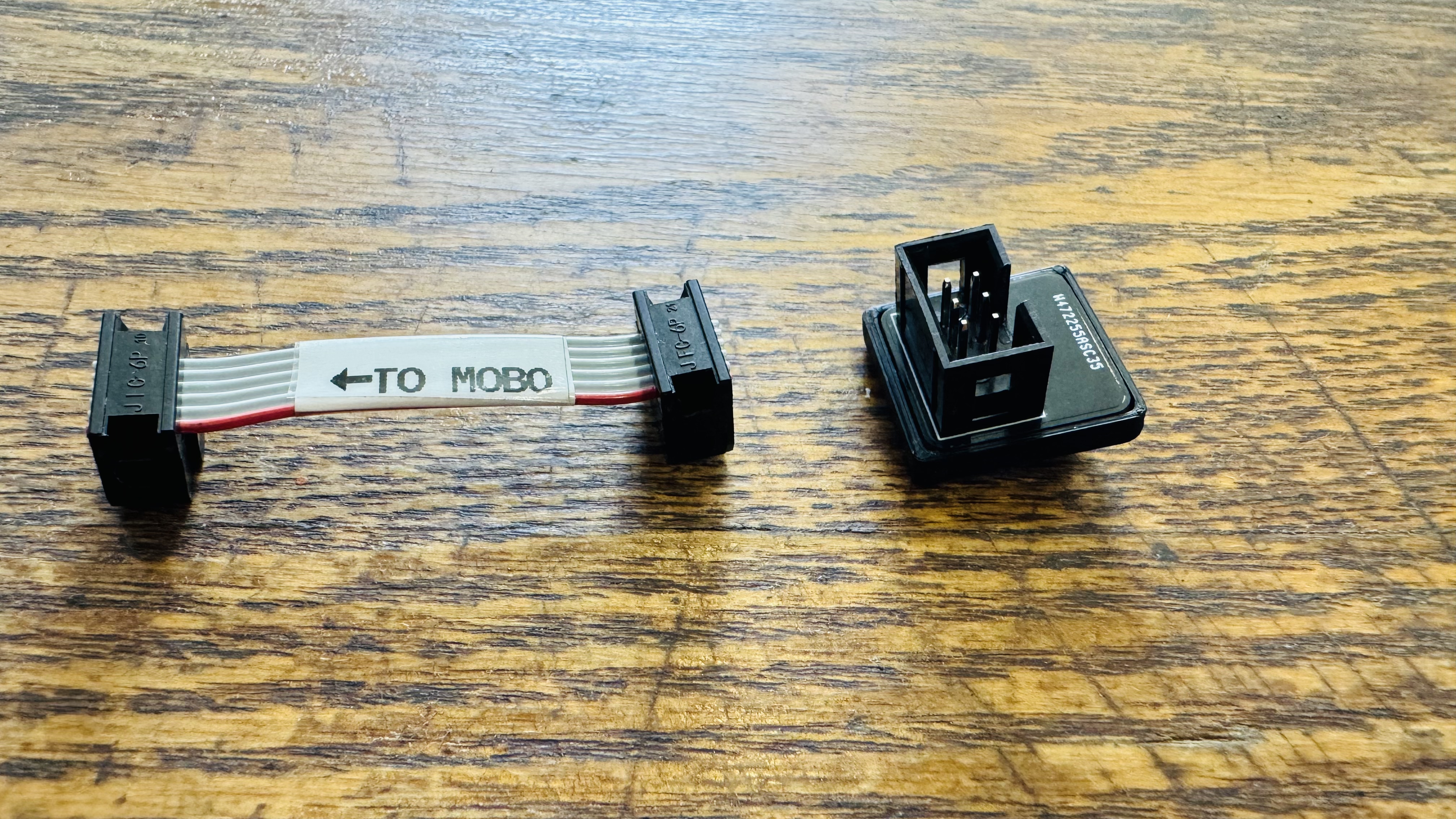
Packing feeder-cable-adapter
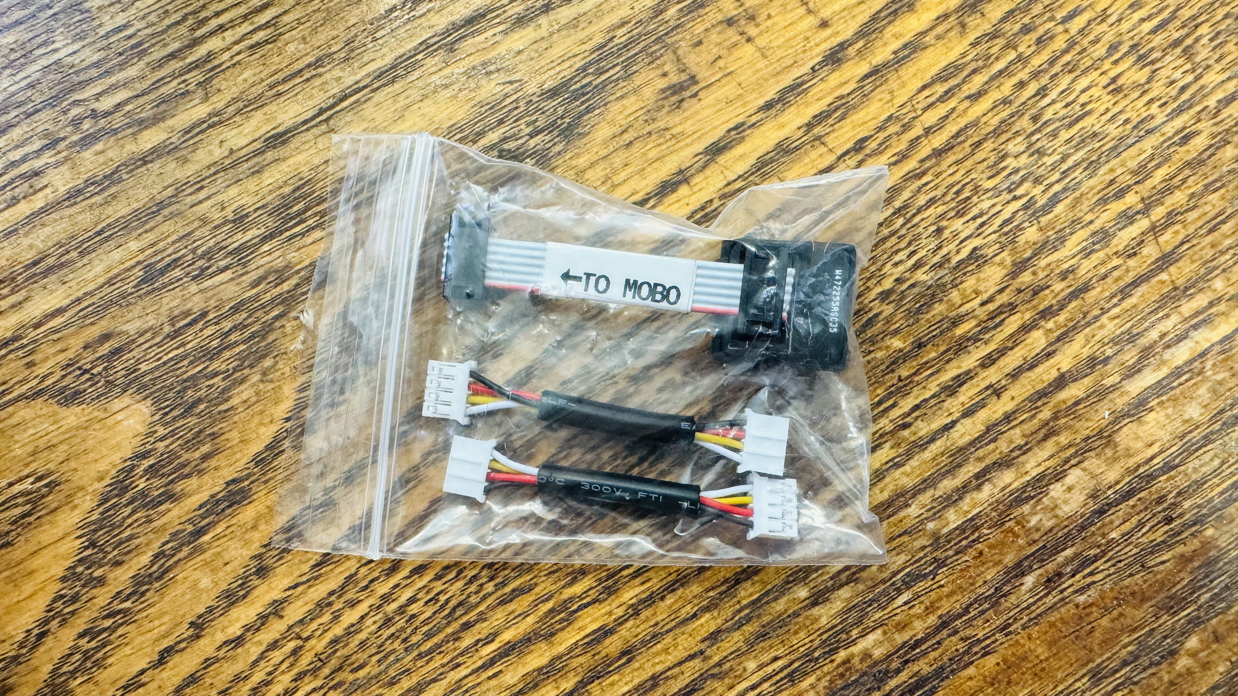
- Add 1x
feeder-blade-idc-adapterand 2xblade-jumper-v4into2x3-bag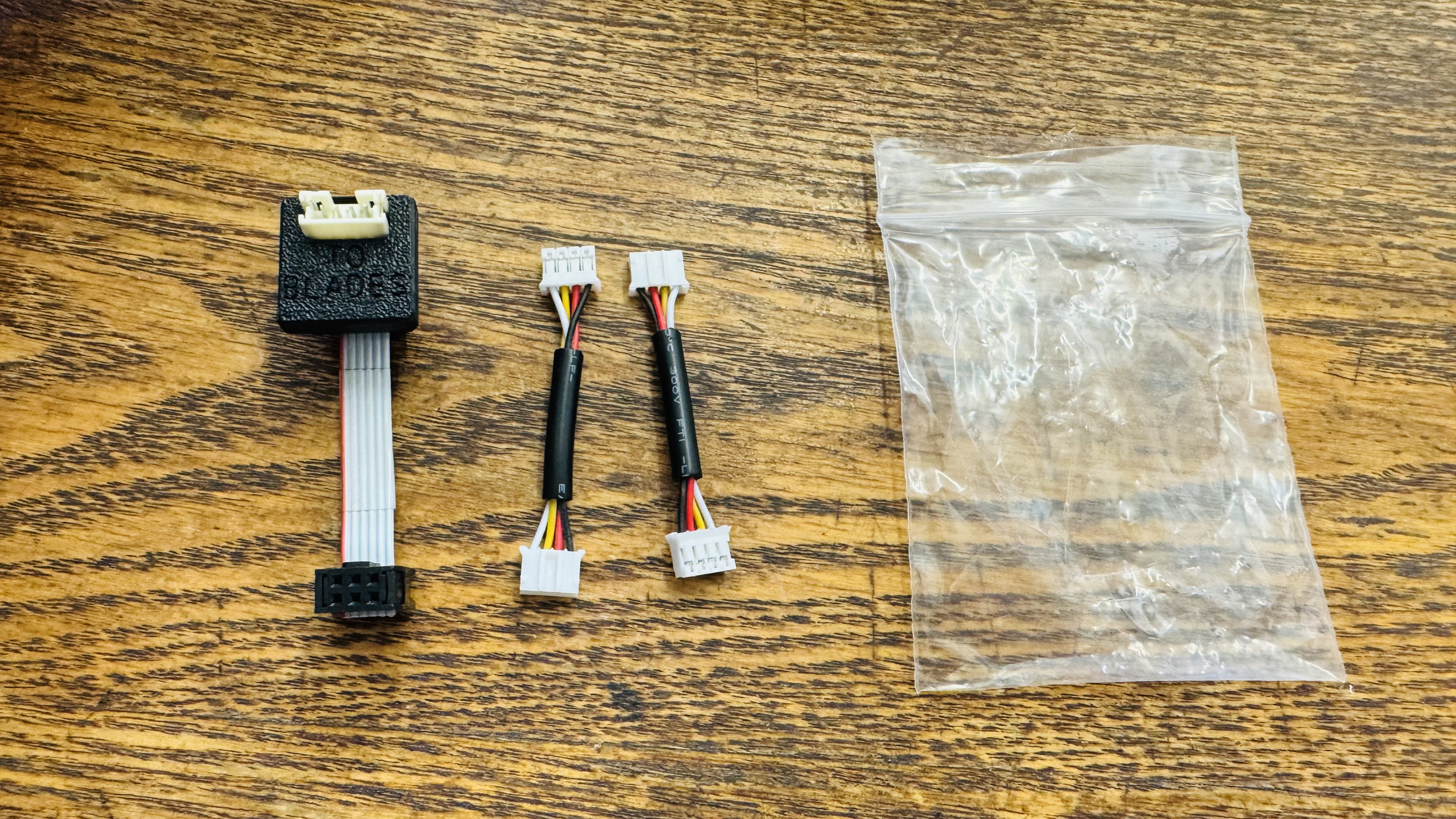
- Seal bag shut
If the feeder-cable-adapter is being prepared for individual sale, adhere a build-number-sticker to the outside of the packaging
These assemblies can now be set aside for further use in packout