feeder-blade-panel (PCBA)
This section will guide the reader on how to properly create a feeder-blade-panel (PCBA)
SMT
- Paste blade panels three at a time.
- Load three pasted blade panels into the Blade Lumen
- Run the job in OpenPnP
- Remove the panels and reflow them in the oven one at a time
- Inspect for any shorts or shifted components and rework as needed
- Add the 120R termination resistor to the 50th slot position if needed
- Place the completed
feeder-blade-panel (PCBA)units into the yellow bin found at the blade assembly work station
Programming
- Grab the stylus from the blade programmer

- Ensure that the address is set to
1- You can adjust the address with the buttons to the right of the screen
-
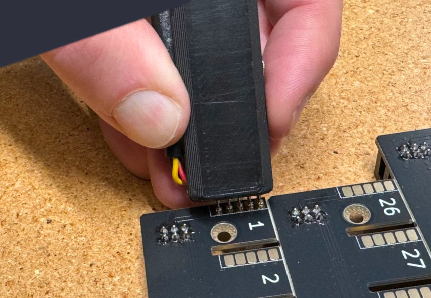
Place the spring pins of the stylus against the pads on
Slot #1- Make sure the orientation matches as shown below:

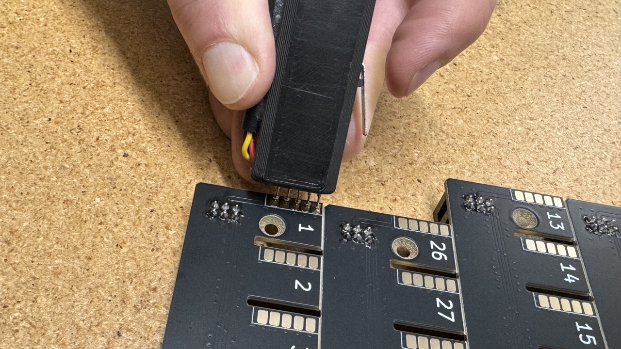
- Make sure the orientation matches as shown below:
-
Press the switch on the stylus when all spring pins are compressed against the pads
-
Look at the screen:
The programming step failed if you see anything other than a
successmessage- The jig is capable of detecting shorts, and will fail programming if one is detected
- The screen will display which pin it sensed has shorted
- If a failure is observed perform any necessary cleanup and try again
- Note that the jig will remember the last place you left off
If the programmer reads
1 - SUCCESSproceed to the next slot position
- The jig is capable of detecting shorts, and will fail programming if one is detected
-
After successfully programming address
1, repeat this step for the next 49 addresses while moving in the following order:
Pink (4th row) → Red (2nd row) → Green (3rd row) → Blue (1st row)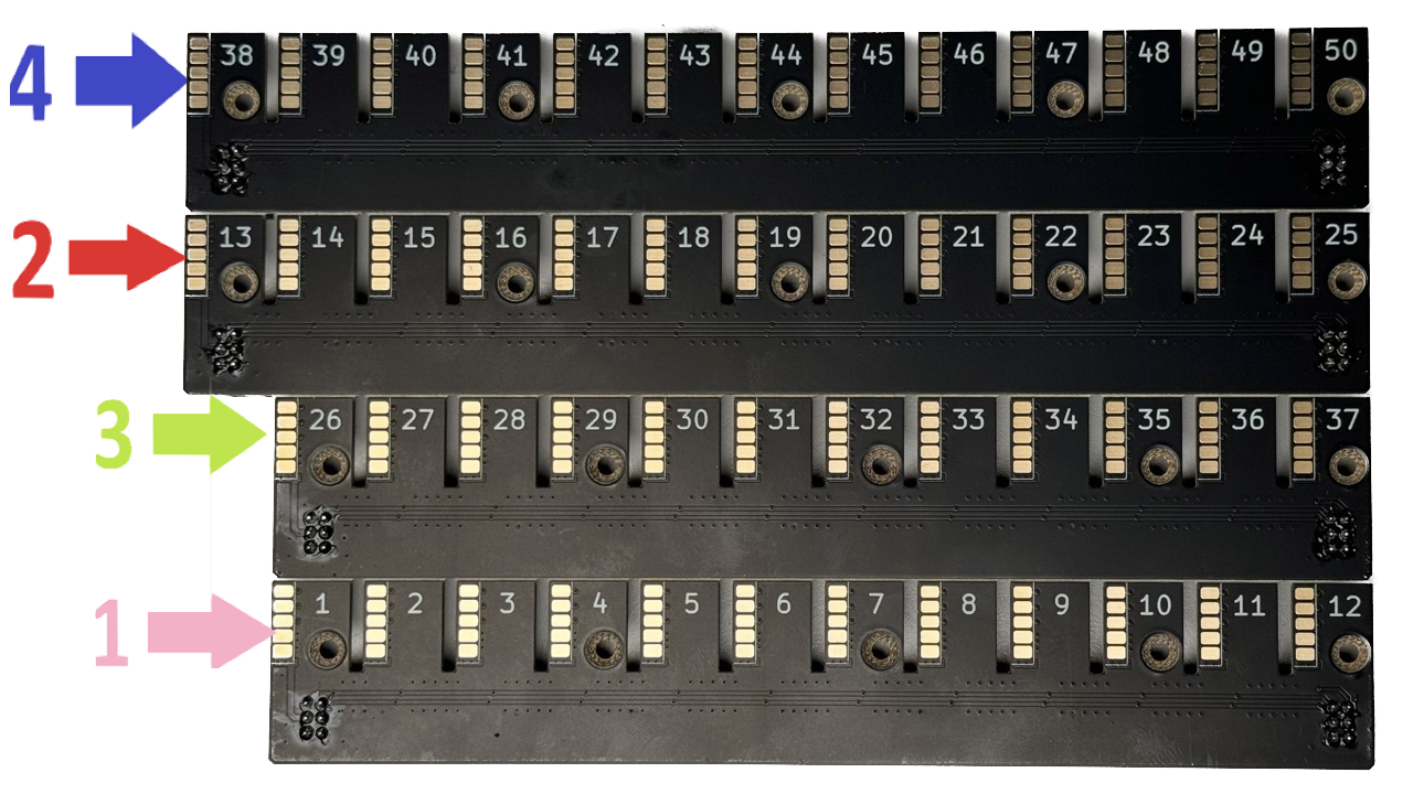
Pay extreme attention to avoid programming any slot with the wrong value
QC
Ensure your completed PCBA meets the following requirements:
-
Switch the programmer to
QC Modeand confirm that Slots #1, #13, #23, #26, #38, #48, and #50 each have a programmed value that matches the top-side silkscreen textFor example:
Confirm that Slot #26 is actually programmed as Slot #26
-
Gold spring finger pads are free of damage
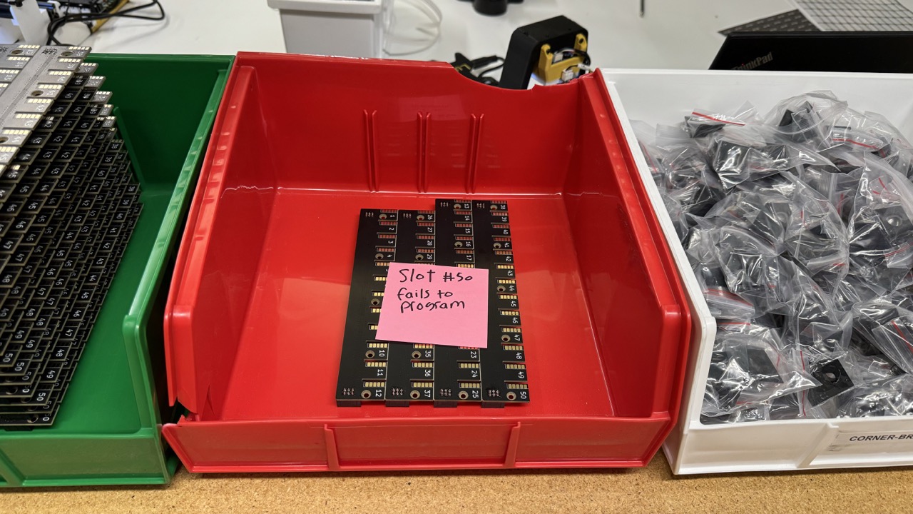
Place each quality checked feeder-blade-panel (PCBA) into the appropriate QC bin:
Place all QC passing feeder-blade-panel (PCBA) units into the green QC bin
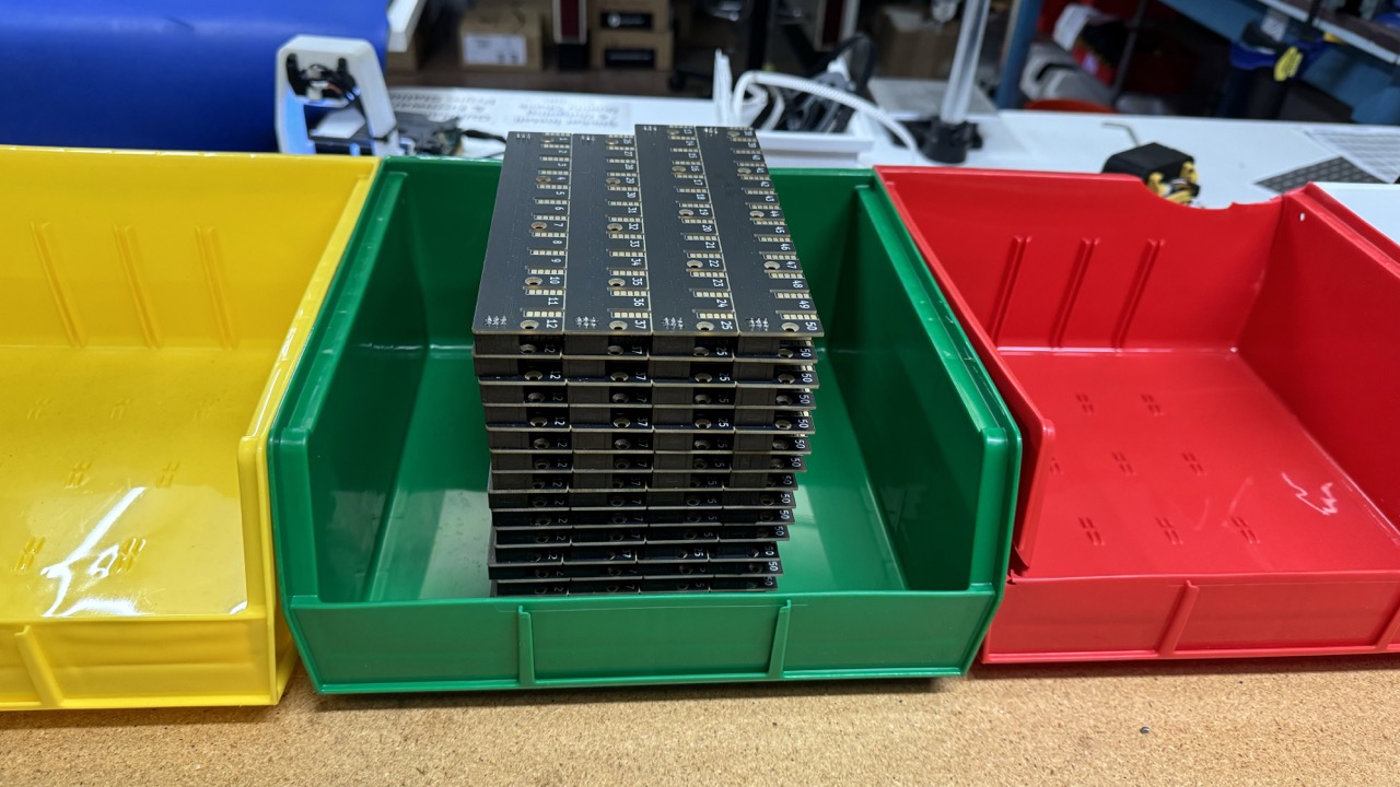
Place all QC failing feeder-blade-panel (PCBA) units into the red QC bin
Be sure to label each defective unit with any issues it has
The next step is to proceed to Feeder Blade Set Final Assembly