Feeder Rail (Front and Rear)
Introduction
The purpose of these work instructions is to cover the assembly process for the LumenPnP's front and rear feeder rail. These rails are used by the LumenPnP to space its two y-gantry assemblies apart. These rails also allow for auto feeders to be installed onto the LumenPnP and electronically connected via the 50x mounted feeder slots.
Assemble feeder-blade-set
If you have not already done so, go to this page for instructions on preparing a feeder-blade-set for use in the LumenPnP Feeder Rails
Assemble front-feeder-rail
Insert extrusion into assembly jig
- Insert a piece of
alu-extrusioninto thefeeder-rail-asm-jig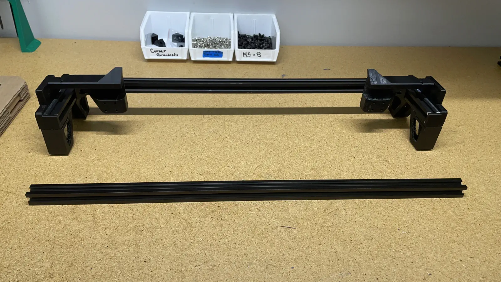
Install corner brackets
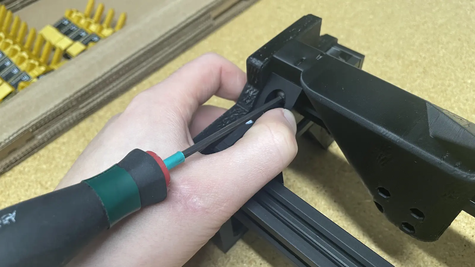
- Loosely install a
M5x8-boltandM5-t-nutonto 2xcorner-bracket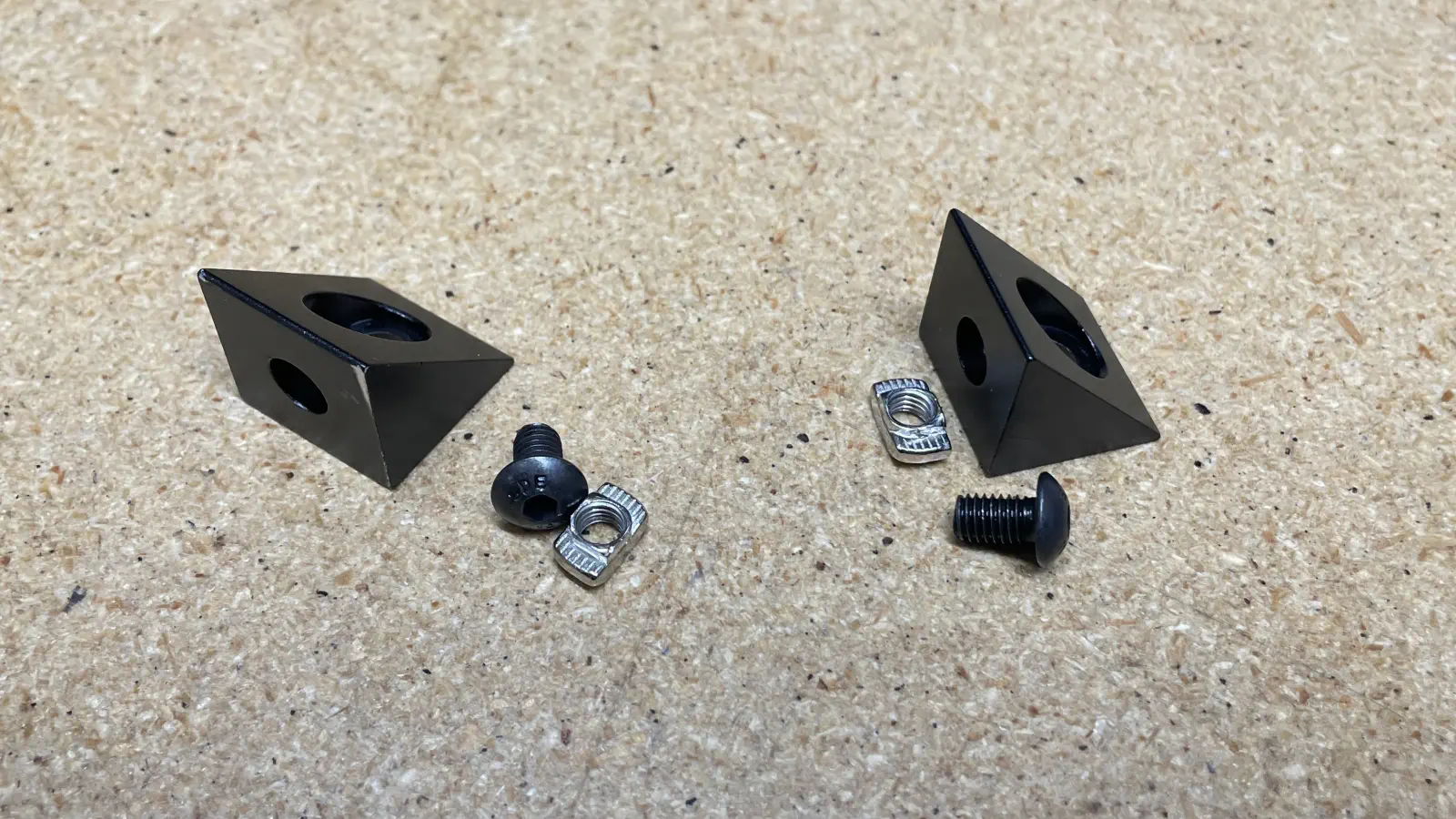
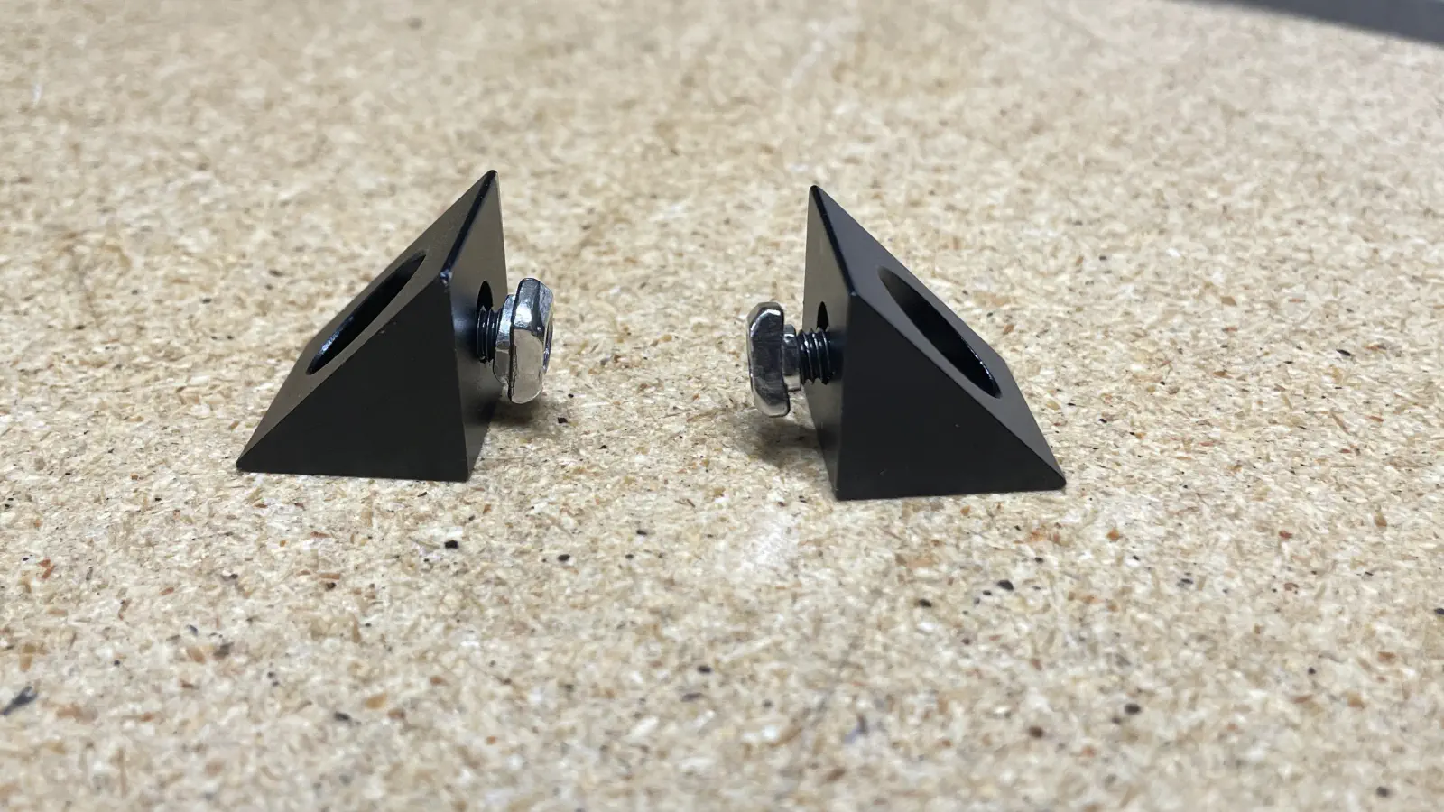
- Position a
corner-bracketonto the front left side of thealu-extrusionpreviously placed in thefeeder-rail-asm-jig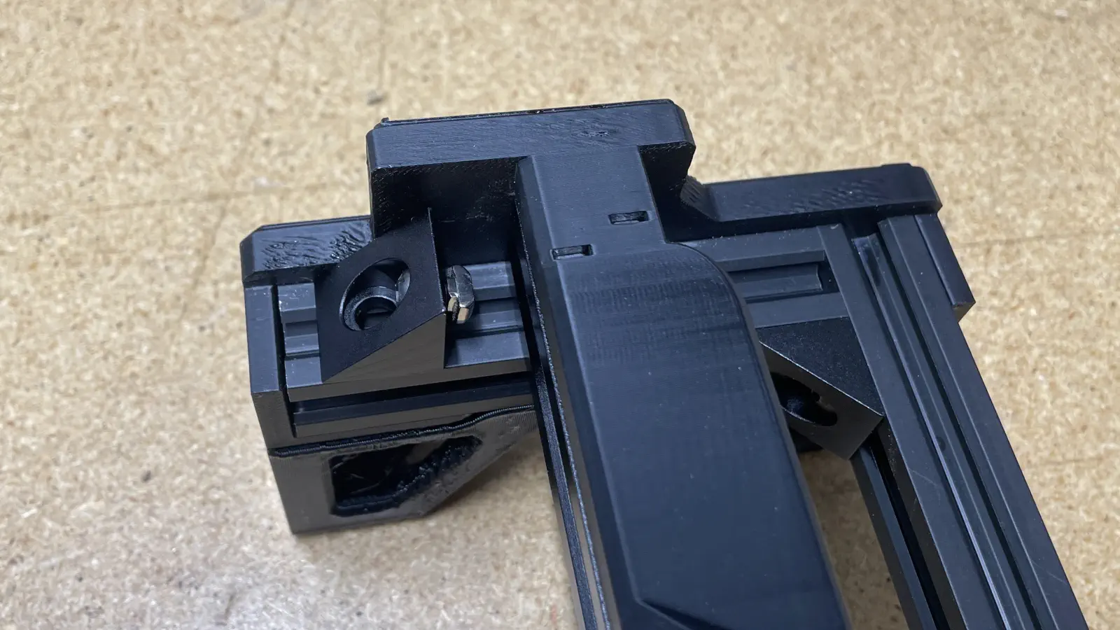
- Press the
corner-bracketdownward and inward (towards the sidewall of the jig) while tightening theM5x8-boltto0.7N/M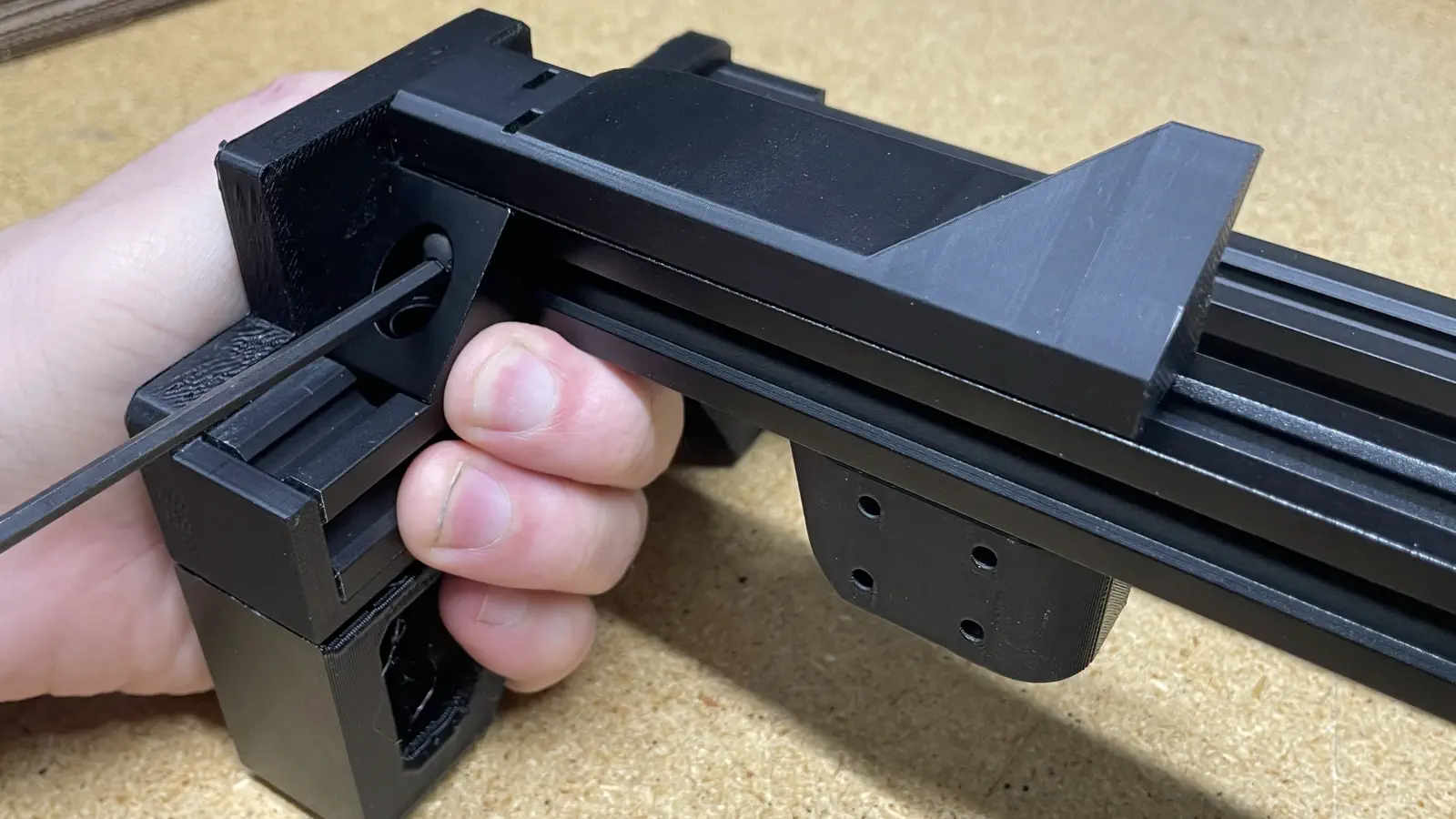
- Repeat the previous two steps on the opposite side of
alu-extrusion
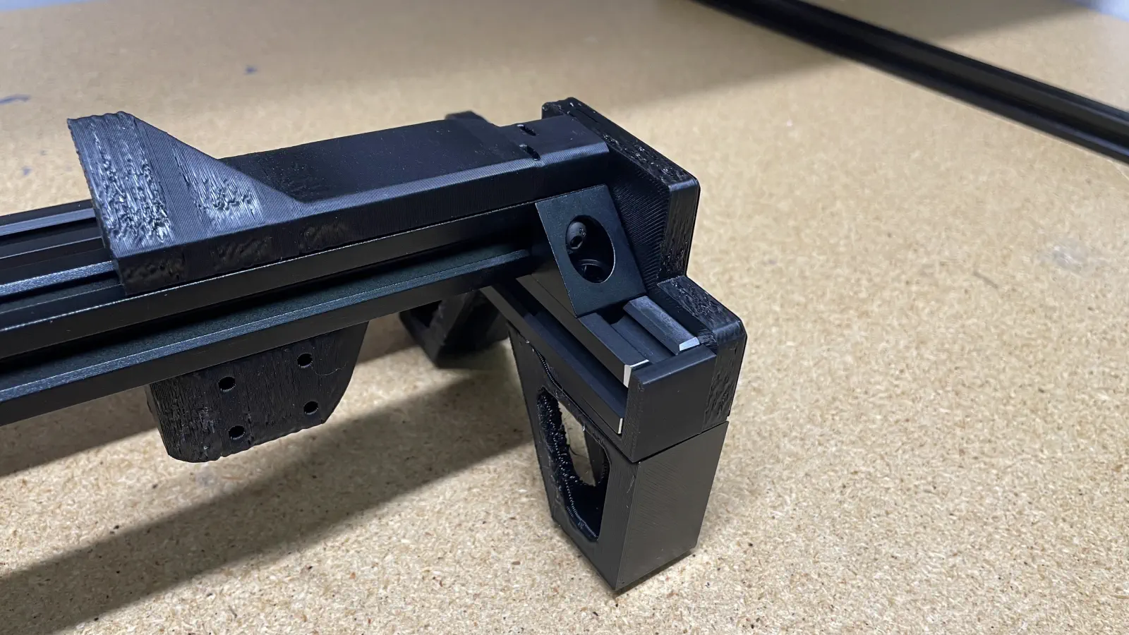
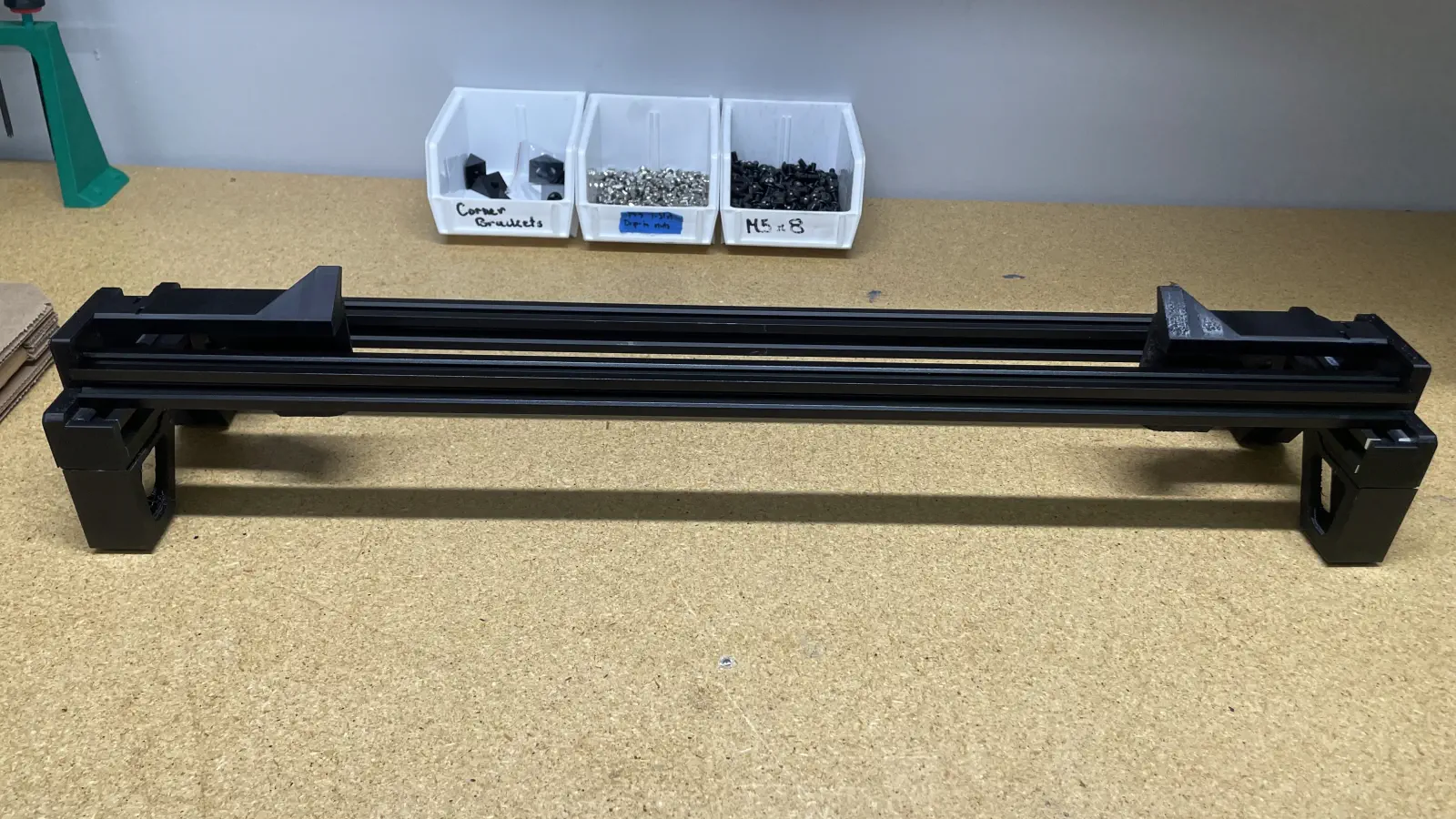
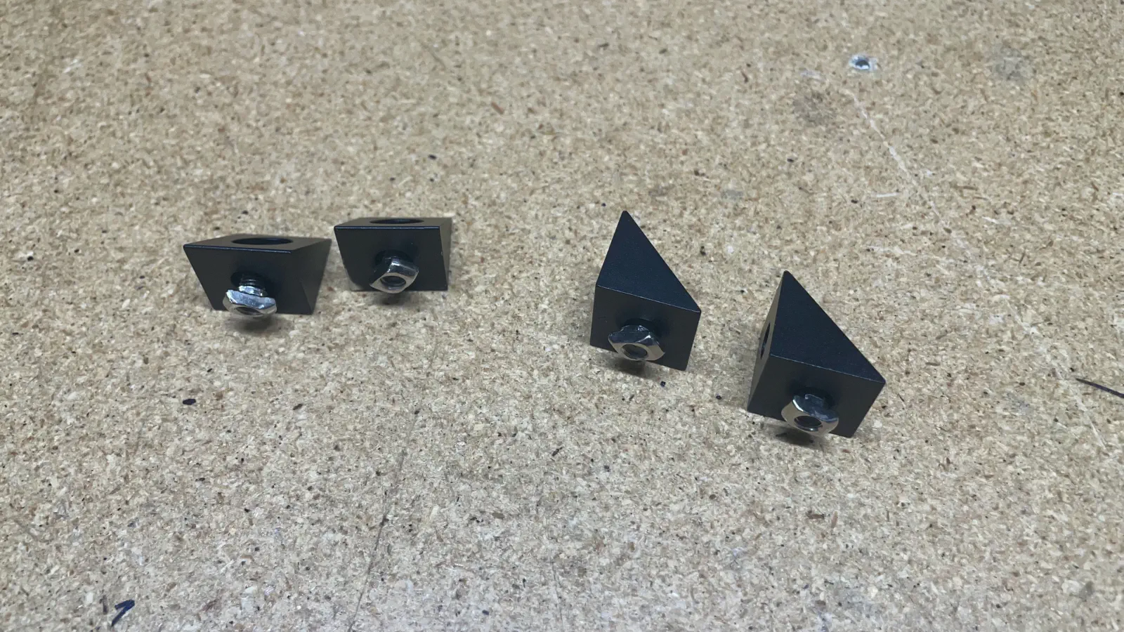
- Confirm the WIP
front-feeder-railmatches the image below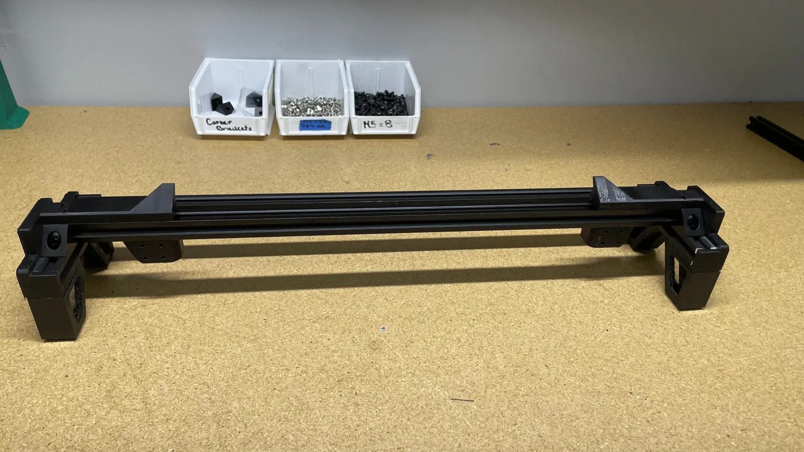
Install feeder blades
-
Collect a
feeder-blade-setfrom inventory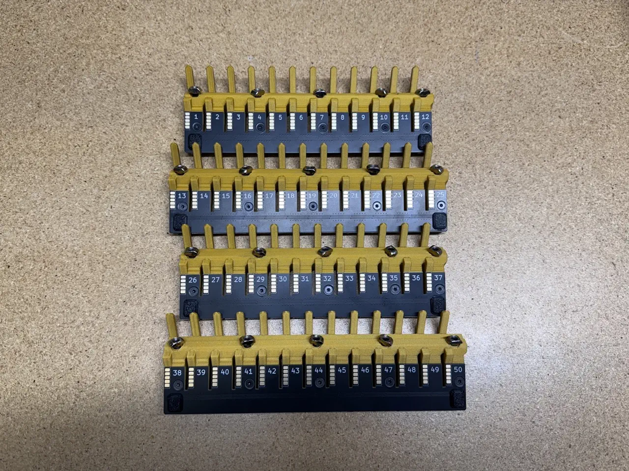
-
Install
Feeder Slot Blade (#1 - #12)onto the front left side of thealu-extrusion- Press the blade assembly downward and inward (towards the sidewall of the jig) while tightening the 5x
M5x10-boltto0.7N/M, starting with the center screw and tighening the screws in pairs moving outwards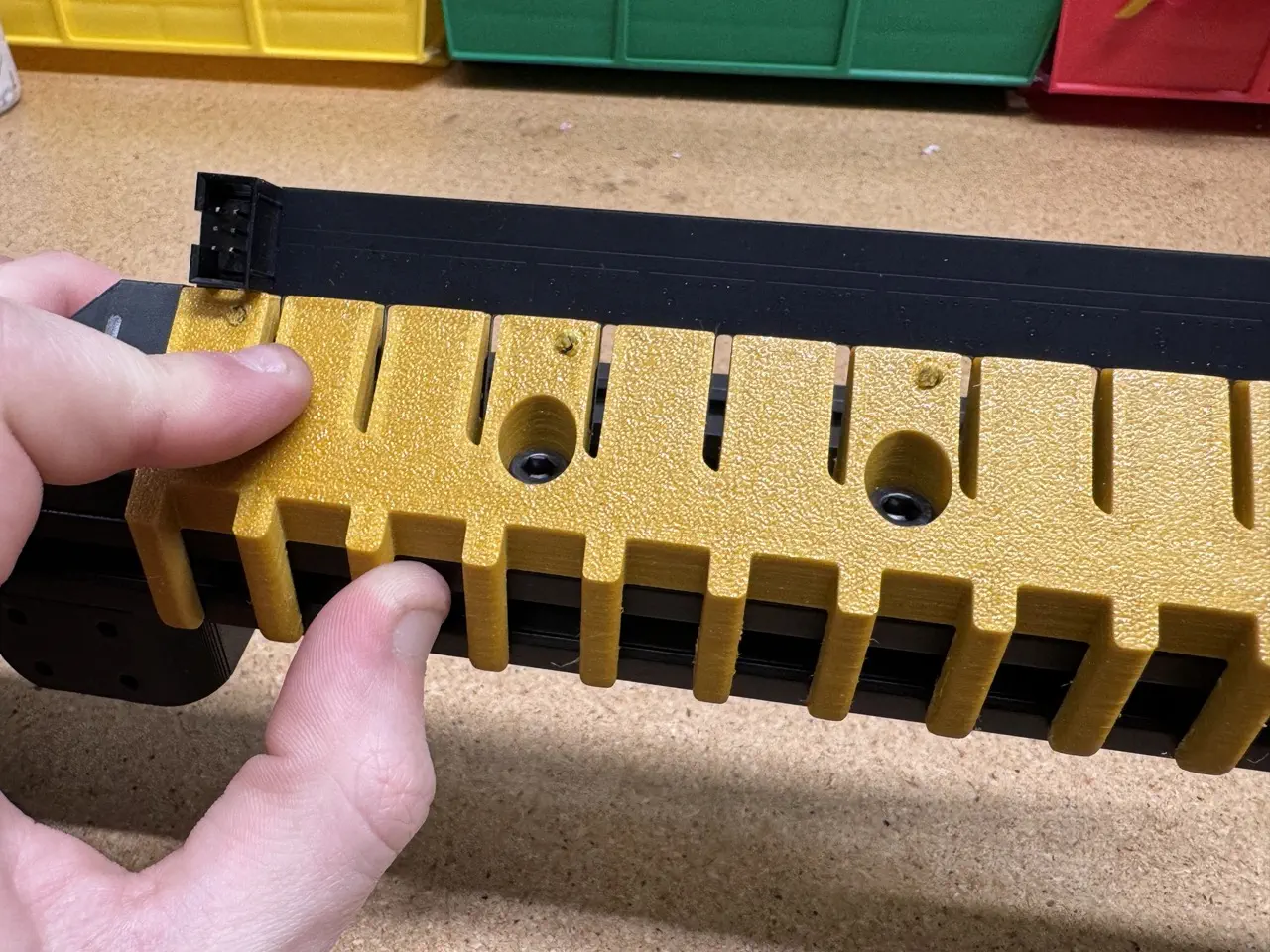
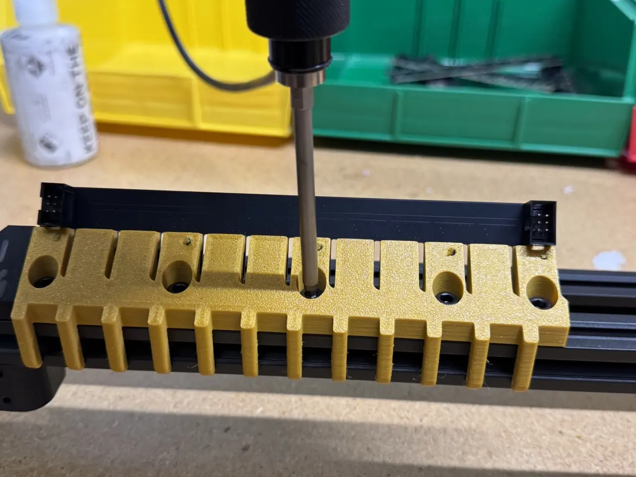
- Press the blade assembly downward and inward (towards the sidewall of the jig) while tightening the 5x
-
Repeat the two previous steps to install
Feeder Slot Blade (#13 - #25)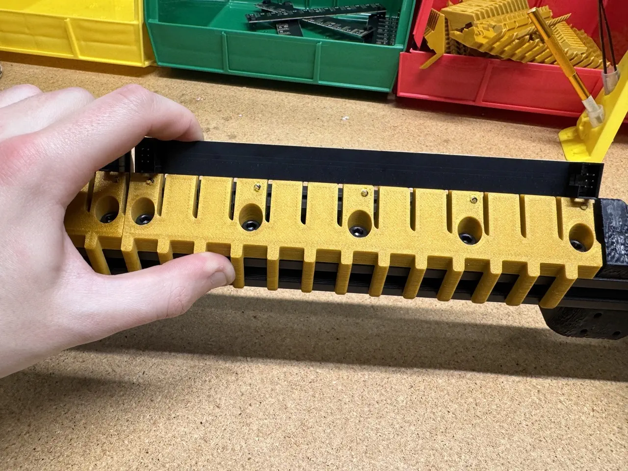
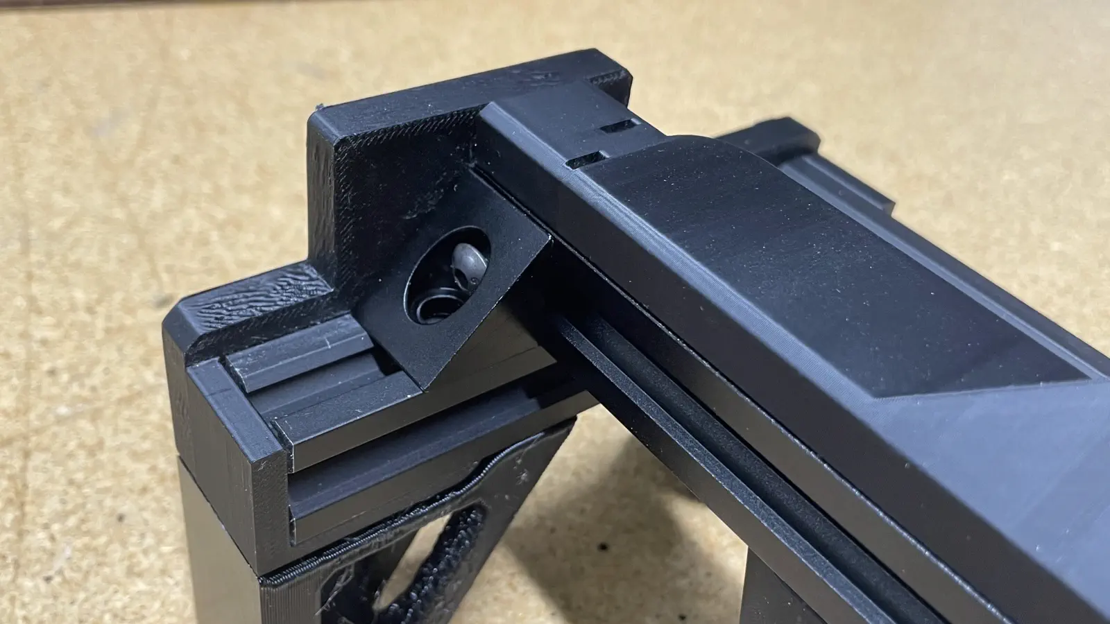
Install blade-jumper-harness
-
Pull the WIP
front-feeder-railoutward to remove it fromfeeder-rail-asm-jig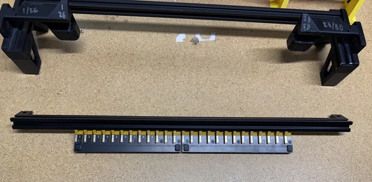
-
Inspect the
blade-jumper-harness. It is critical that the order of the conductors in this jumper are the exact same for each connector when the connectors are facing the same way.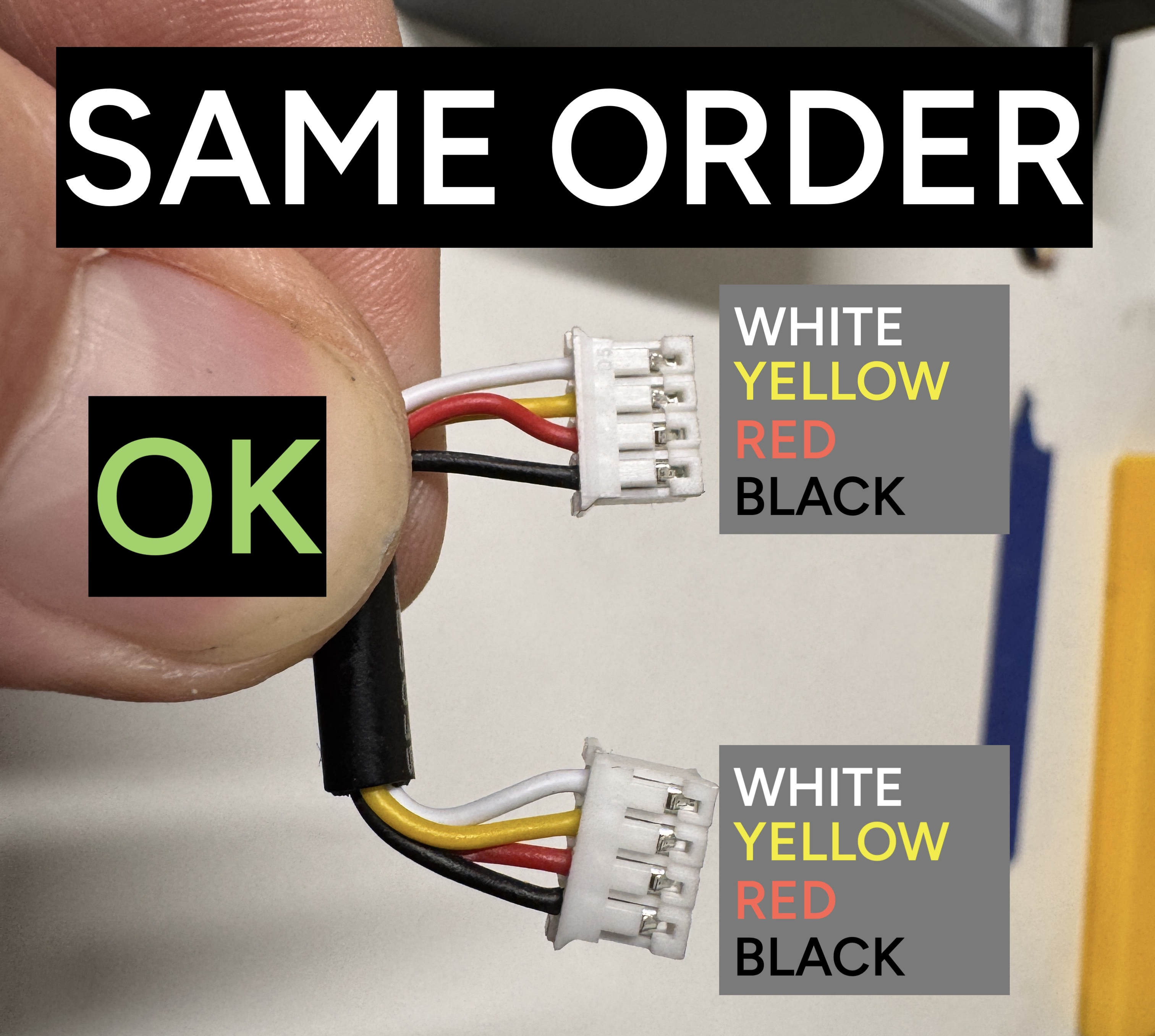
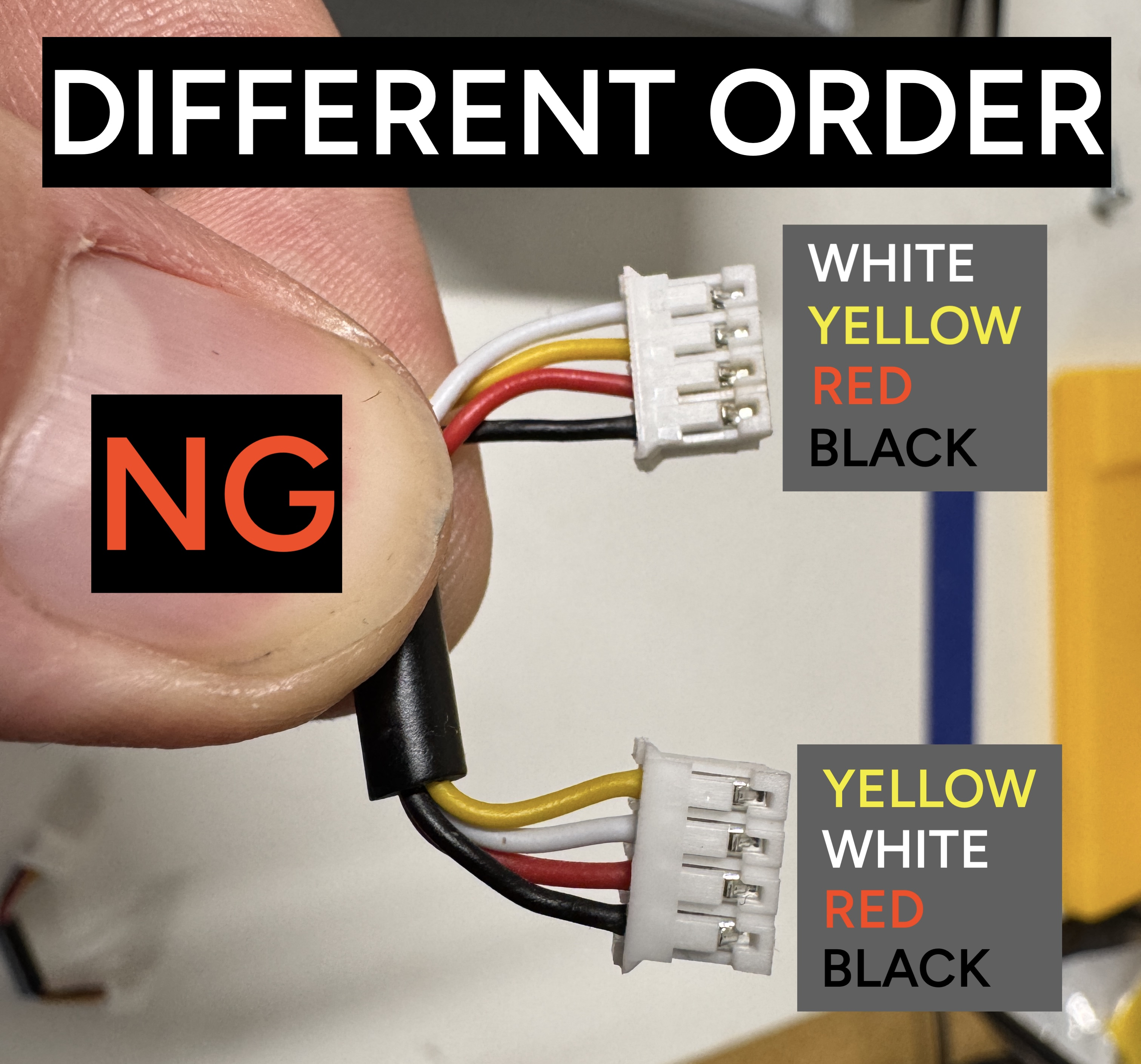
CRITCAL
Even after you've checked this cable, check it again! It is critically important that this jumper has the exact same order of wire color for both connectors.
-
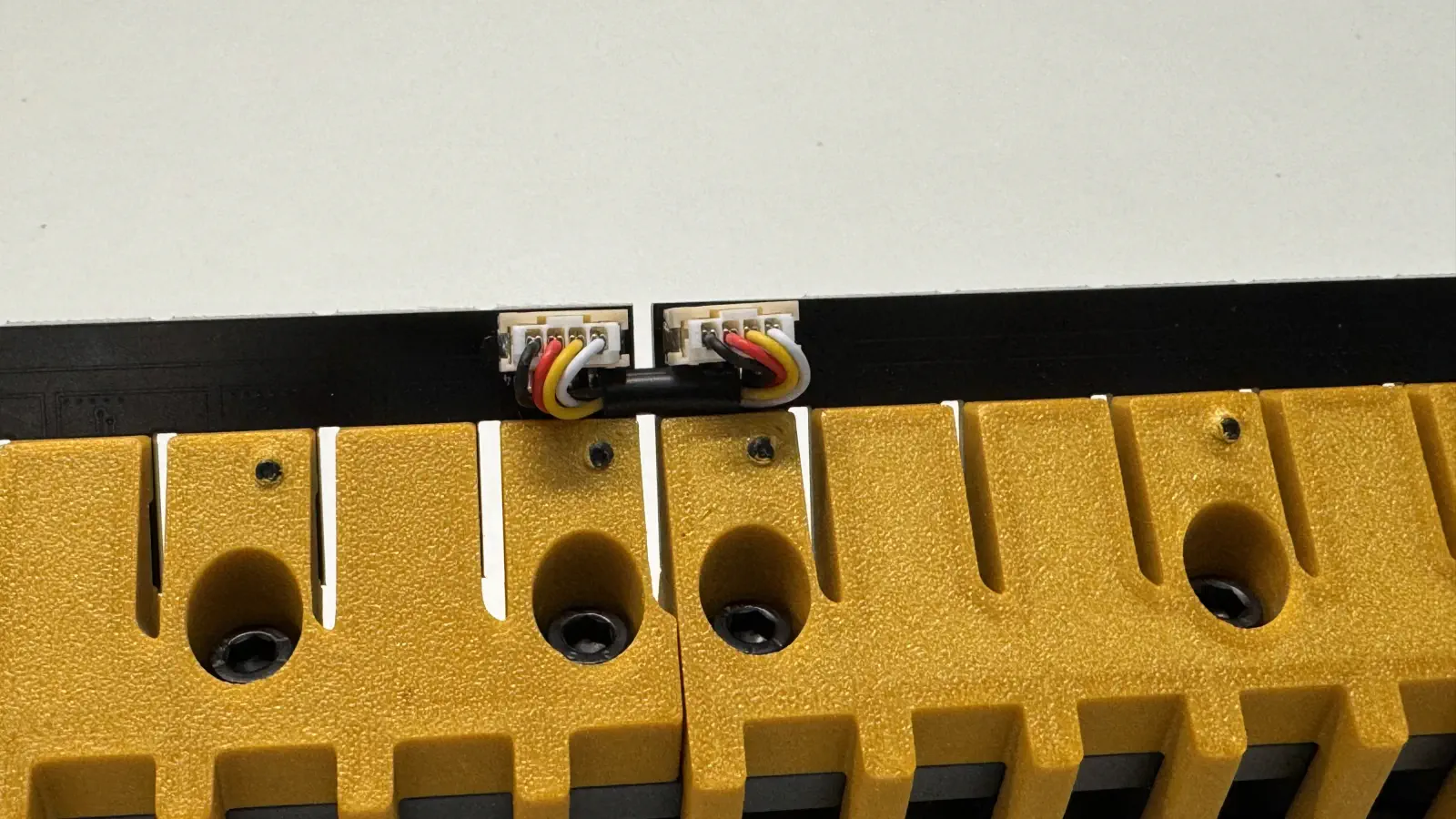
Connect
blade-jumper-harnessto the twoPH-connectorlocated betweenFeeder Slot Blade (#1 - #12)andFeeder Slot Blade (#13 - #25)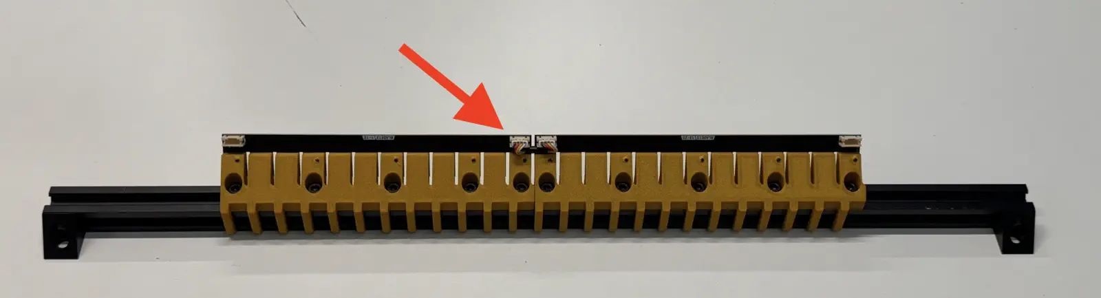
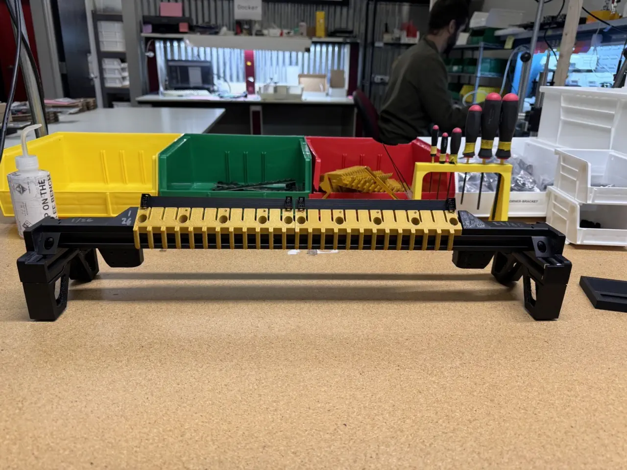
OQC
Perform the following quality control checks:
- Feeder blades are installed sequentially from left to right
- Wiggle the installed blades to ensure no screws are loose, retightening any if needed
- Ensure the print is free of defects and fits flush to `alu-extrusion
- The 2x installed
corner-bracketpieces are flush to thealu-extrusion - Confirm
blade-jumper-harnessis installed into the blades - Tug on the connectors to ensure they're fully connected
- Ensure the wire color order is the same for both connectors on the jumper harness
If all checks pass, bring the completed front-feeder-rail to the shelf for peer-review and pack-out.
Assemble rear-feeder-rail
This section of the work instruction will be a little less detailed than the above section on front-feeder-rail as it builds off the same process.
Insert extrusion into assembly jig
- Insert a piece of
alu-extrusioninto thefeeder-rail-asm-jig
Install corner brackets
- Loosely install a
M5x8-boltandM5-t-nutonto 4xcorner-bracket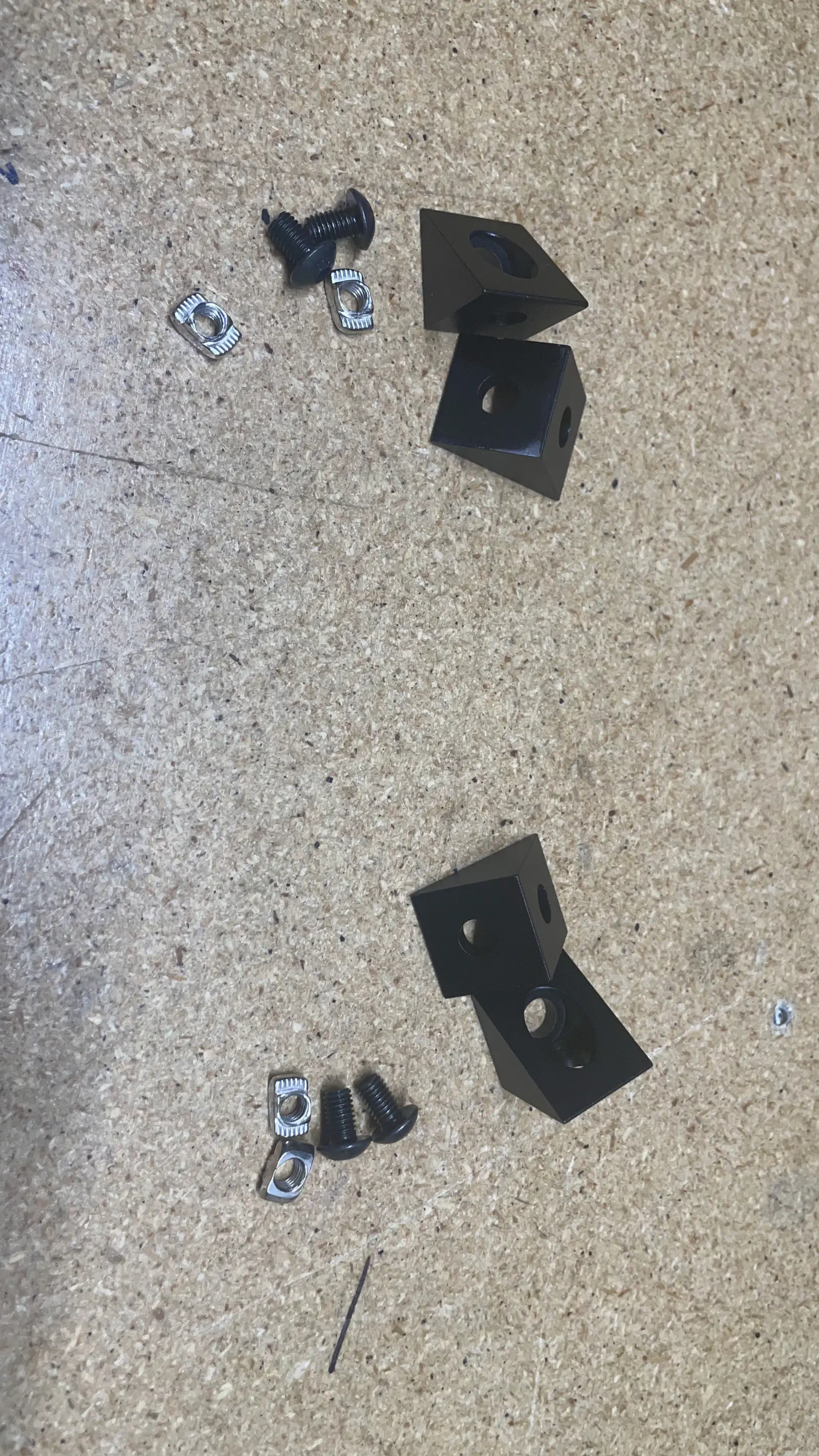
- Position a
corner-bracketonto the front left side of thealu-extrusion
- Press the
corner-bracketdownward and inward (towards the sidewall of the jig) while tightening theM5x8-boltto0.7N/M - Repeat the previous two steps on the opposite side of
alu-extrusion
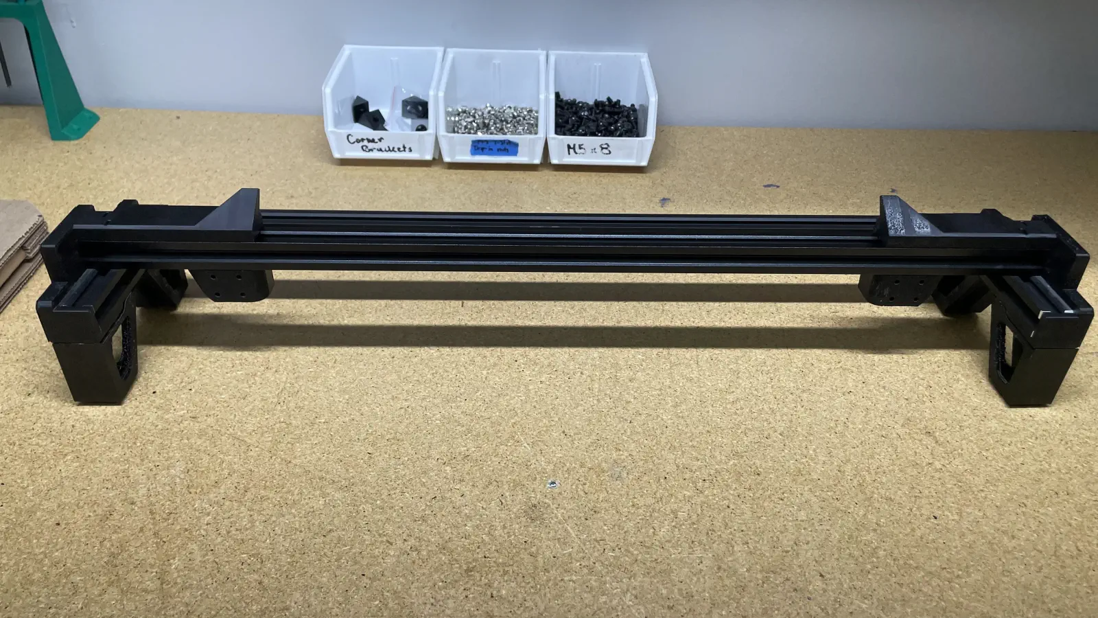
- Confirm the WIP
rear-feeder-railmatches the image below before proceeding to install 2xcorner-bracketon the backside of thealu-extrusion -
Position a
corner-bracketonto the back right side of thealu-extrusion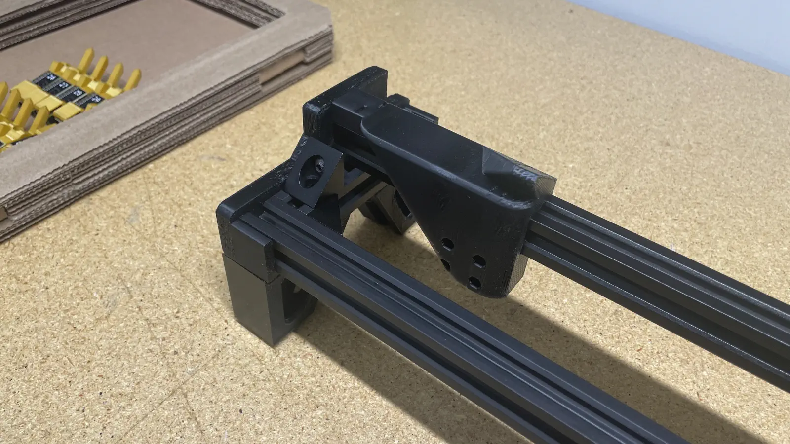
-
Press the
corner-bracketdownward and inward (towards the sidewall of the jig) while tightening theM5x8-boltto0.7N/M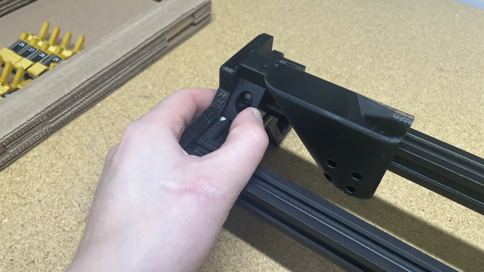
- Repeat the previous two steps to install a
corner-bracketonto the back left side ofalu-extrusion
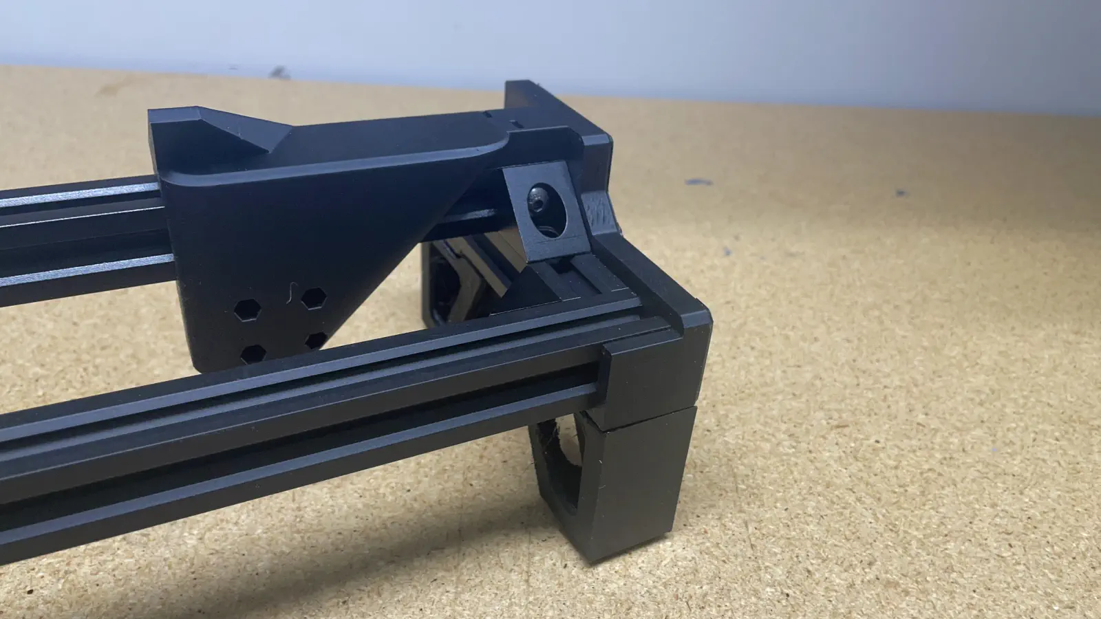
- Confirm the WIP
rear-feeder-railmatches the image below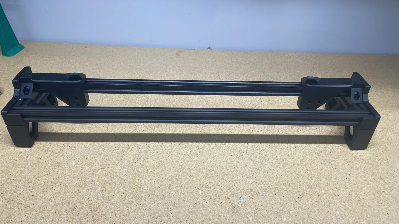
Install feeder blades
-
Install
Feeder Slot Blade (#26 - #37)onto the left side ofalu-extrusion- Press the blade downward and inward (towards the sidewall of the jig) while tightening the 5x
M5x10-boltto0.7N/M, starting with the center screw and tighening the screws in pairs moving outwards
- Press the blade downward and inward (towards the sidewall of the jig) while tightening the 5x
-
Repeat the two previous steps to install
Feeder Slot Blade (#38 - #50)
Install blade-jumper-harness
-
Pull the WIP
rear-feeder-railoutward to remove it fromfeeder-rail-asm-jig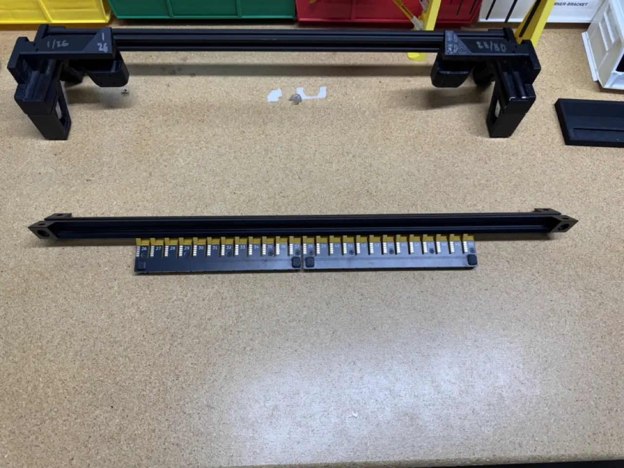
-
Inspect the
blade-jumper-harness. It is critical that the order of the conductors in this jumper are the exact same for each connector when the connectors are facing the same way.
CRITCAL
Even after you've checked this cable, check it again! It is critically important that this jumper has the exact same order of wire color for both connectors.
-
Connect
blade-jumper-harnessto the twoPH-connectorlocated betweenFeeder Slot Blade (#26 - #37)andFeeder Slot Blade (#38 - #50)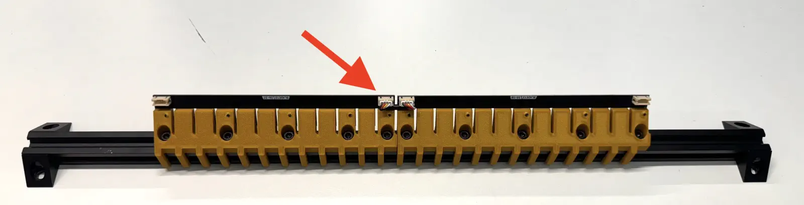
OQC
Perform the following quality control checks:
- Feeder blades are installed sequentially from left to right
- Wiggle the installed blades to ensure none are loose, retightening any if needed
- The 2x installed
corner-bracketpieces are flush to thealu-extrusion - The 4x installed
corner-bracketpieces are flush to thealu-extrusion - Confirm
blade-jumper-harnessis installed into the blades - Tug on the connectors to ensure they're fully connected
- Ensure the wire color order is the same for both connectors on the jumper harness
If all checks pass, bring the completed rear-feeder-rail to the shelf for peer-review and pack-out