Feeder Slot Set
This section will guide the reader on how to properly assemble and package a feeder-blade-set
Materials Prep
- Check 2x
blade-12and 2xblade-13using the granite block to ensure the print printed without warping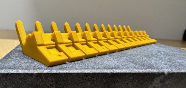
Assembly Process
-
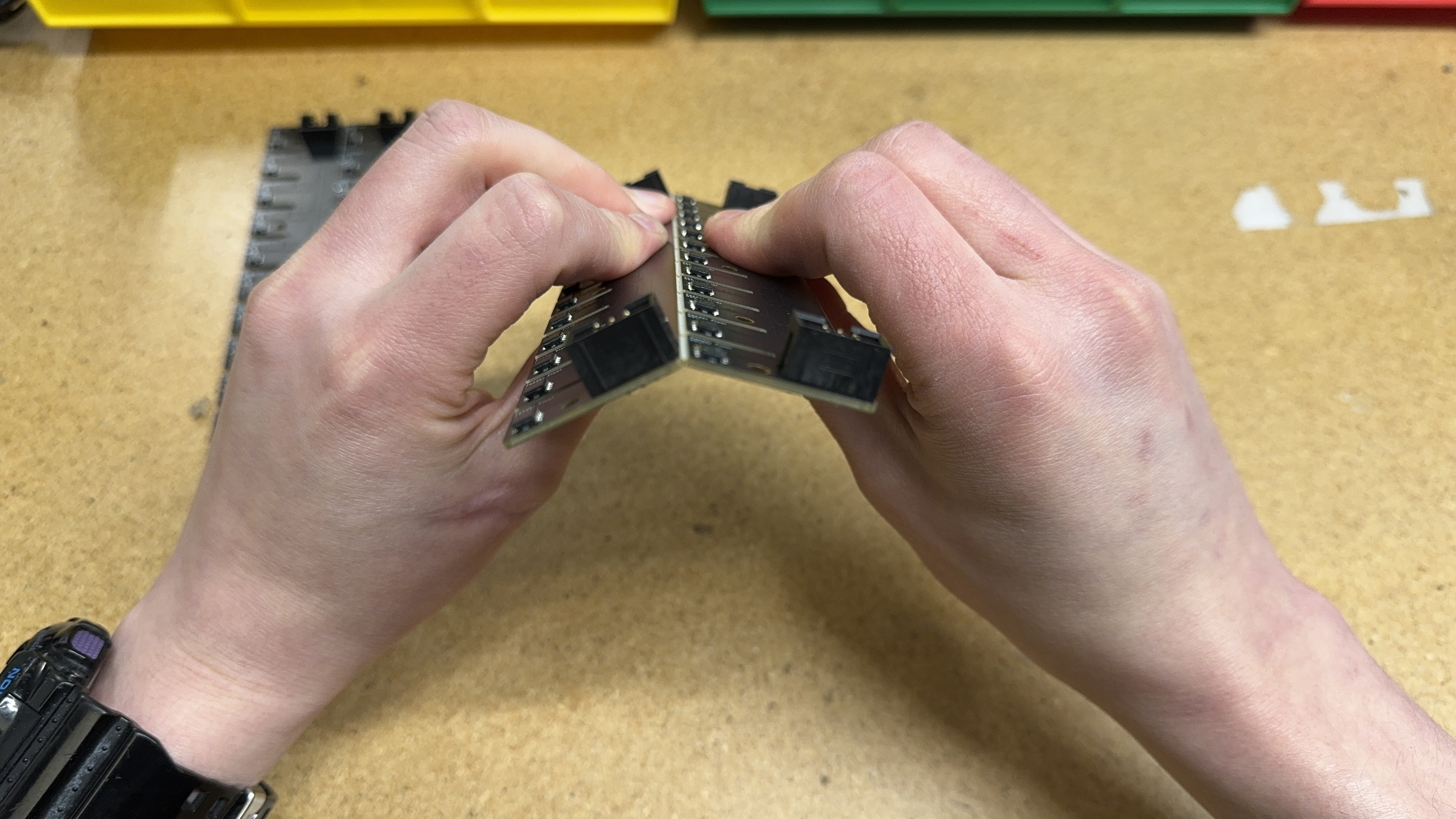
Begin by separating a
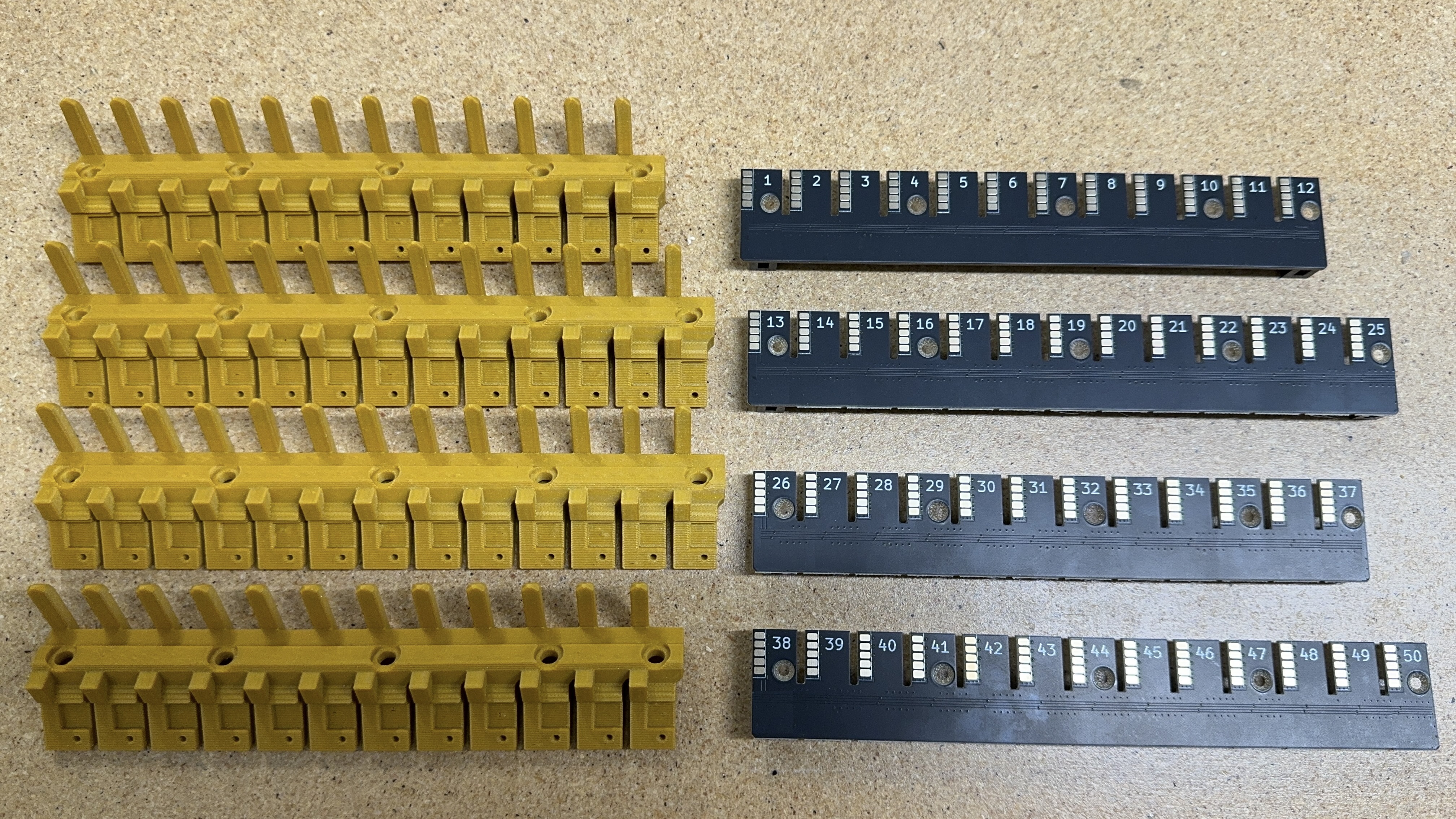
feeder-blade-panel (PCBA)into four separate rows
-
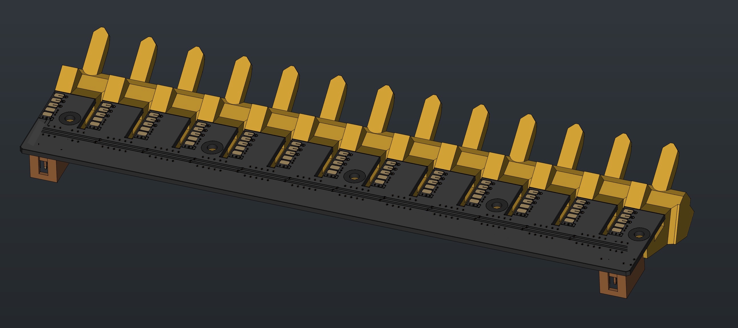
Install each
blade13-pcbinto ablade133D print to createfeeder-blade13-asm
-
Set
feeder-blade13-asminto thefeeder-blade-cradle-jig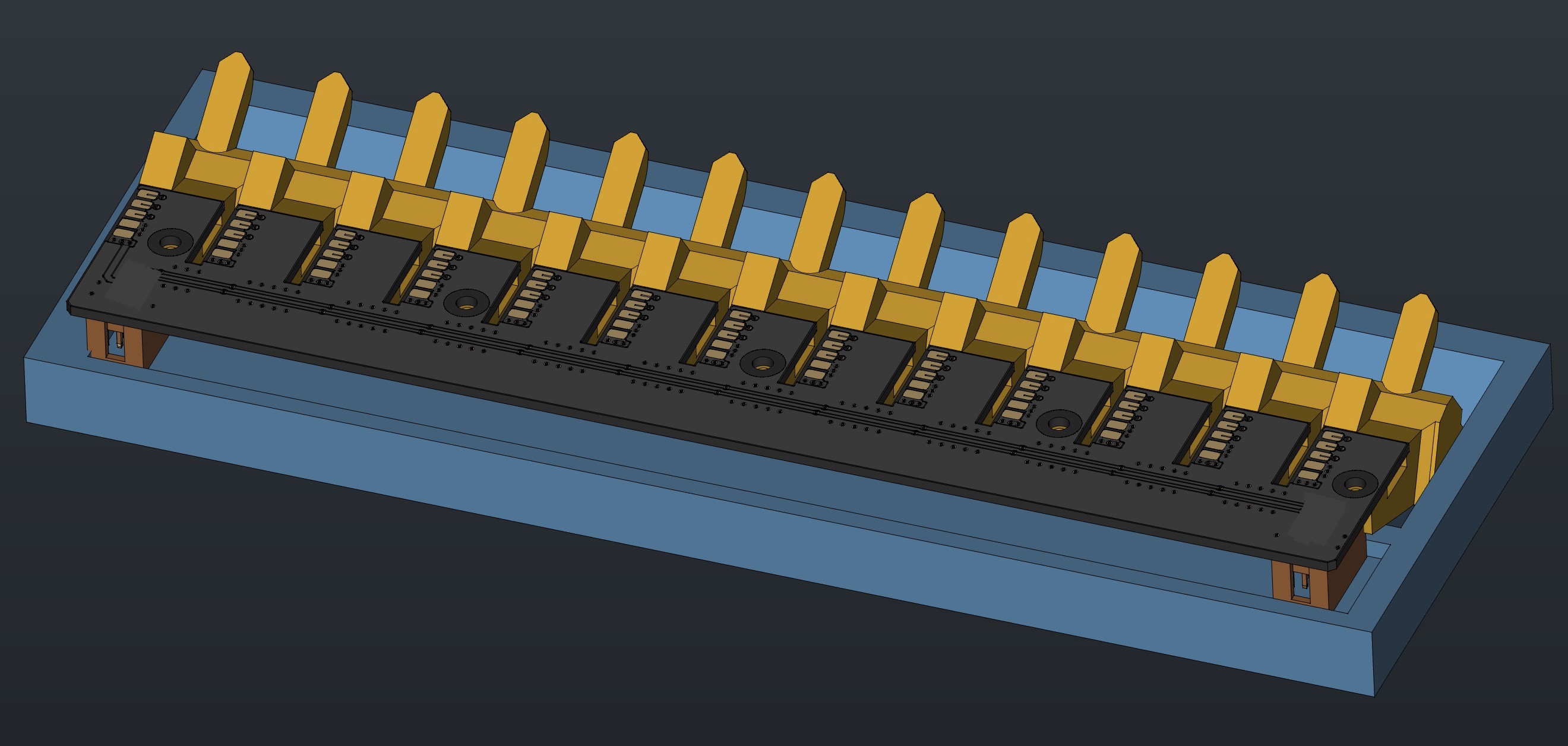
-
Proceed to install 5x
M3x8-self-threading-screwinto the WIPfeeder-blade13-asm- Use an automatic torque driver set to
6
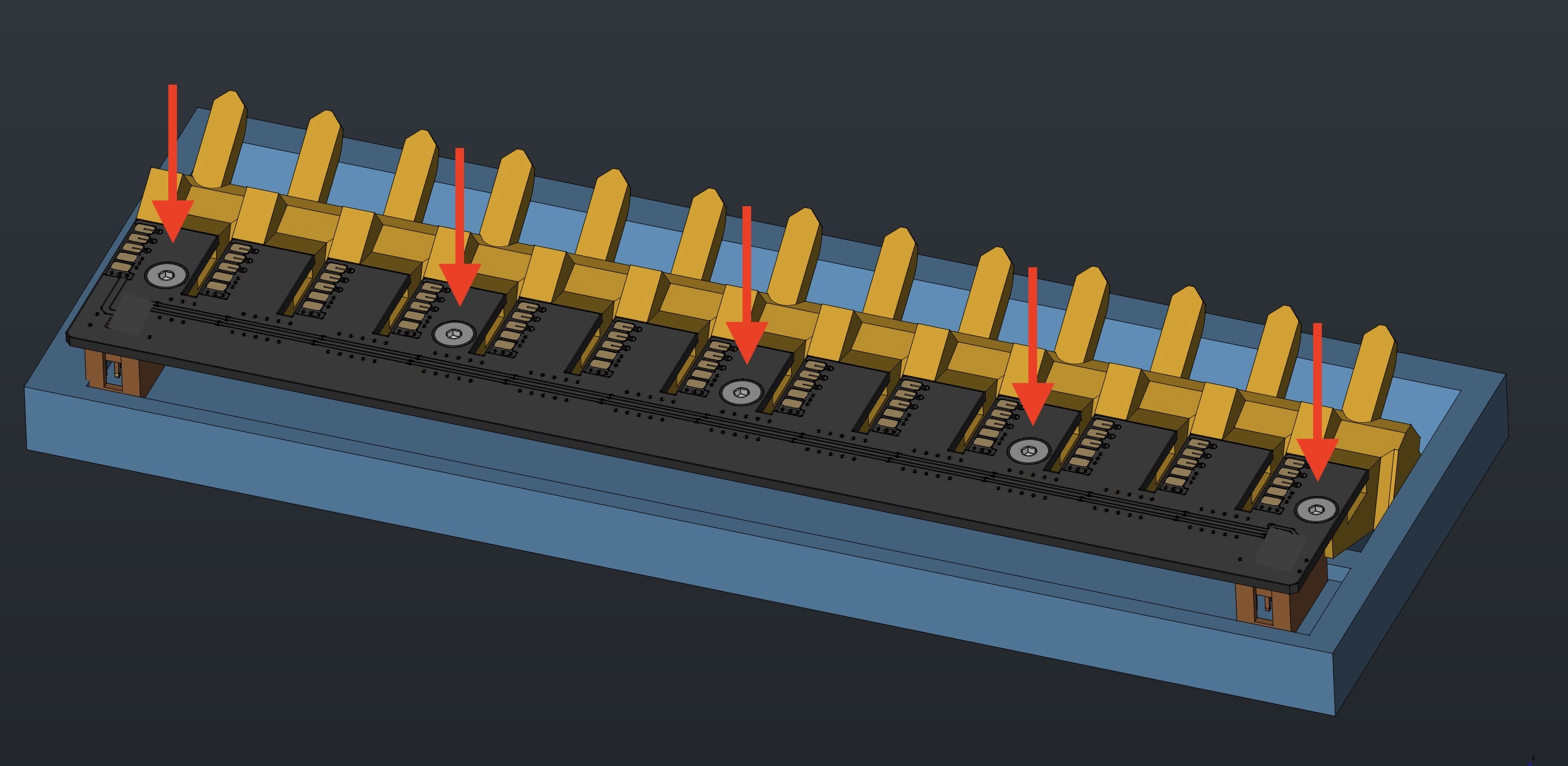
- Use an automatic torque driver set to
-
Remove the blades from the
feeder-blade-cradle-jig -
Loosely install 5x
M5-t-slot-nutand 5xM5x10-boltinto each feeder blade for subsequent use in mounting onto a feeder rail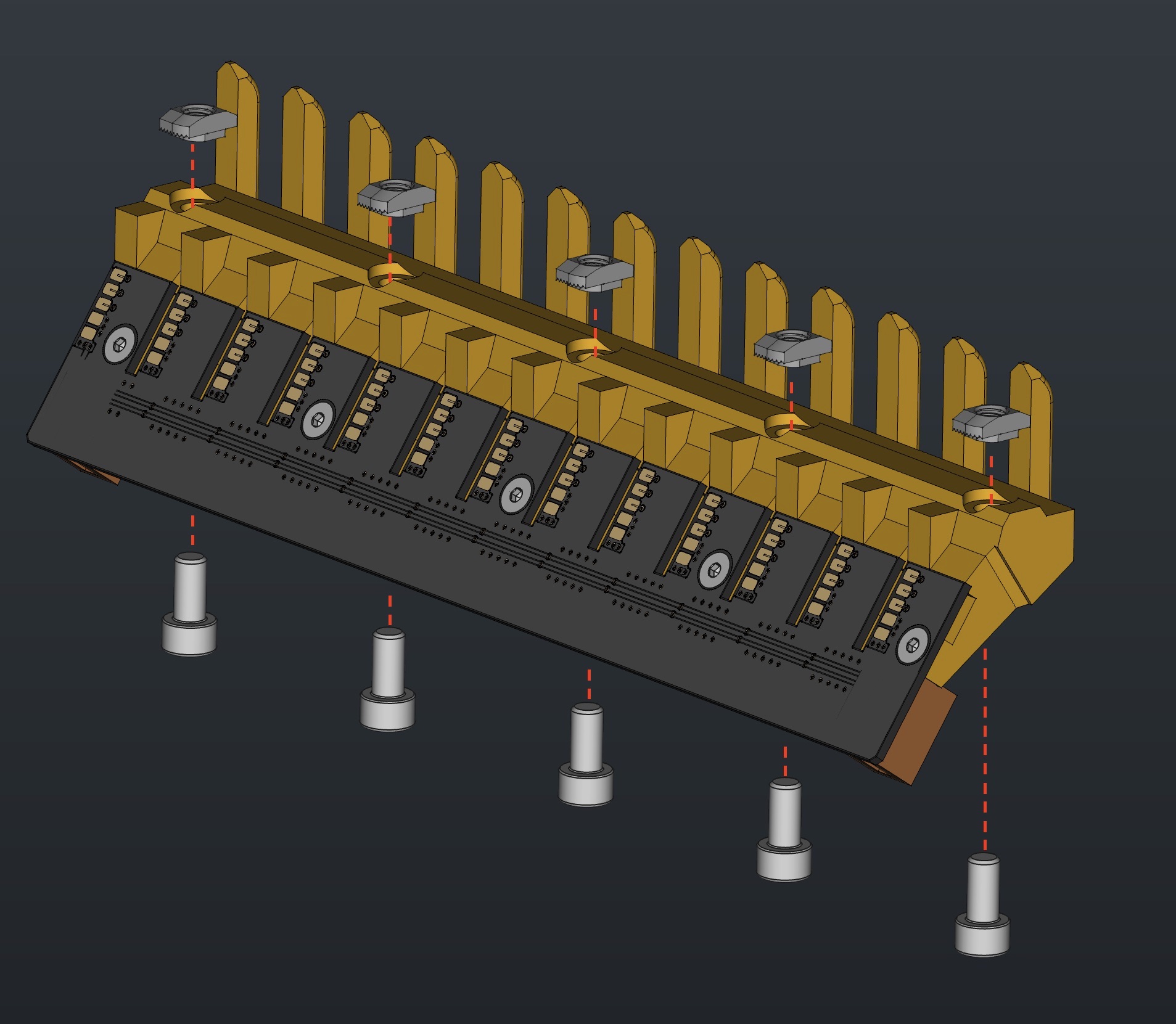

-
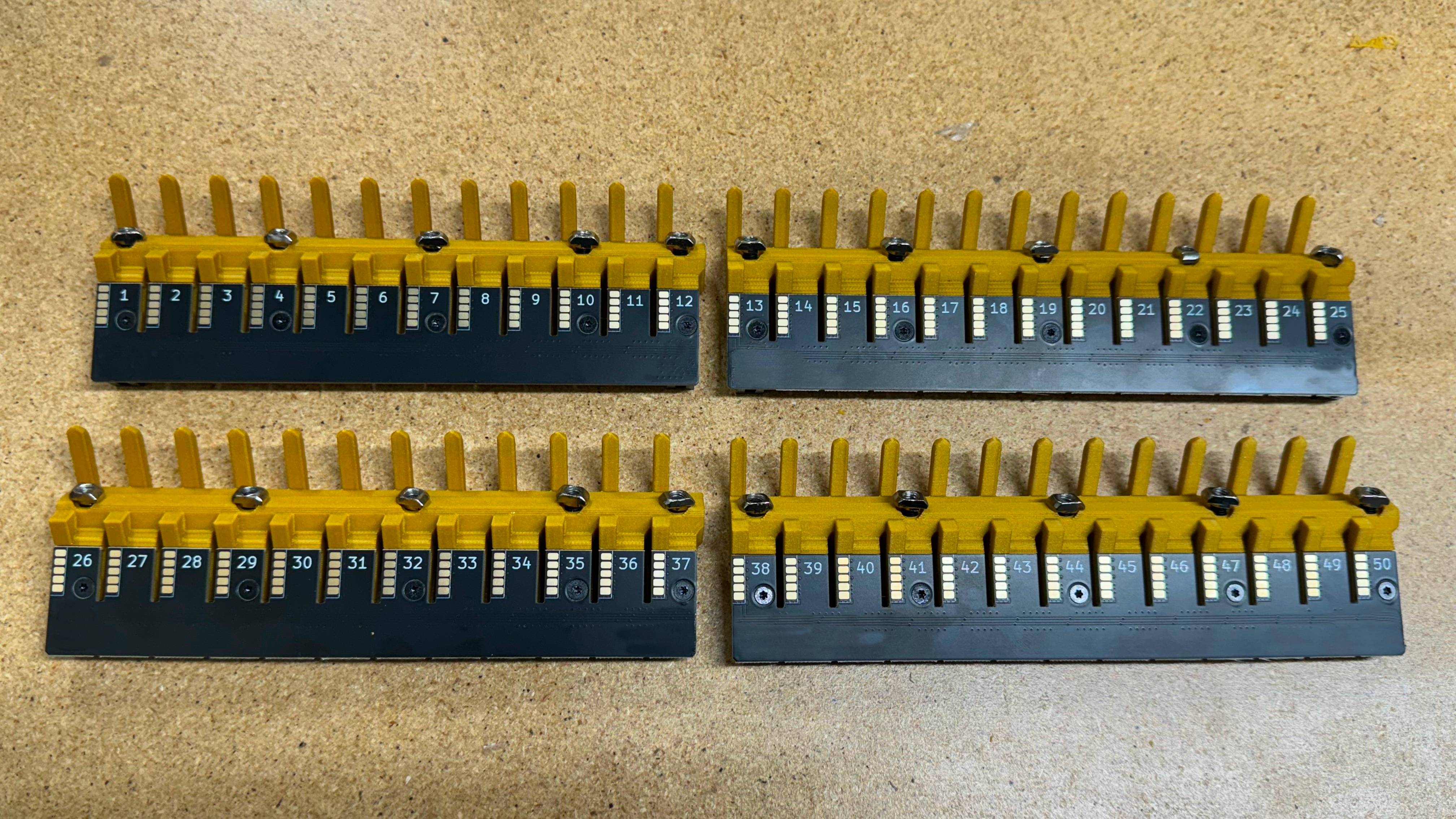
Repeat these above steps until you have created 2x
feeder-blade13-asmand 2xfeeder-blade12-asm- The steps to make the
feeder-blade12-asmare the same as the 13-gang version, the only differences are that the 3D print and PCB are a 12-slot variant.
- The steps to make the
Once all 4 assemblies have been prepared, you have finished building a feeder-blade-set
Next Steps
The next step is to proceed to either:
Feeder Accessory Preparation- provided you are making a Feeder Connection KitFront-feeder-rail / Rear-feeder-rail- provided you are making a LumenPnP