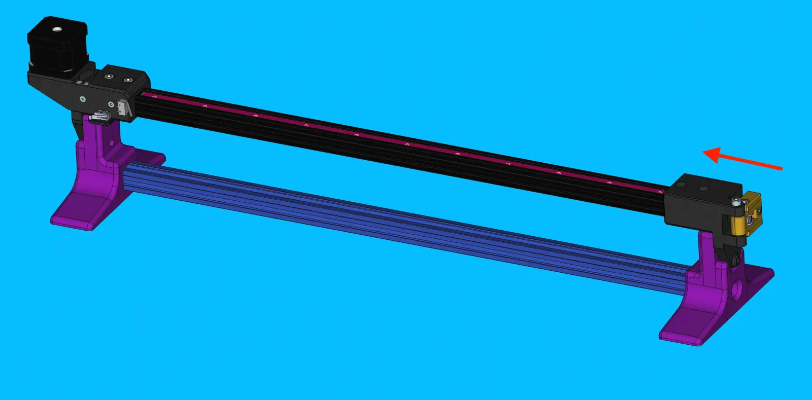
X Gantry
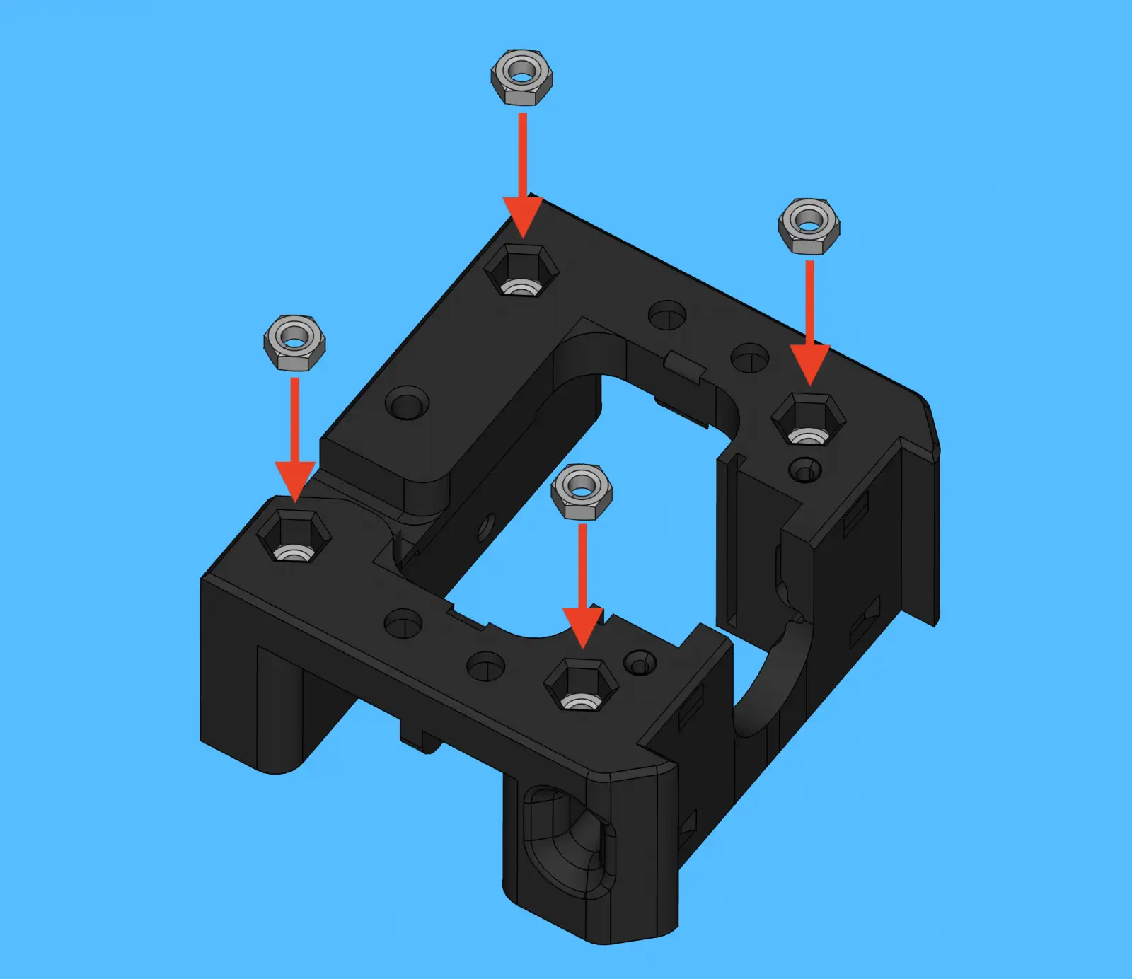
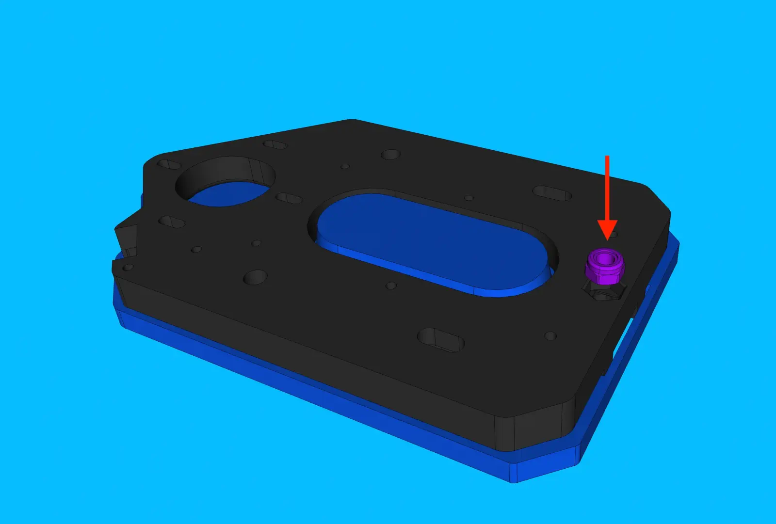
Step 1 of 37
Install backside fasteners
-
Insert 4x
m5-hex-lock-nutinto the following region
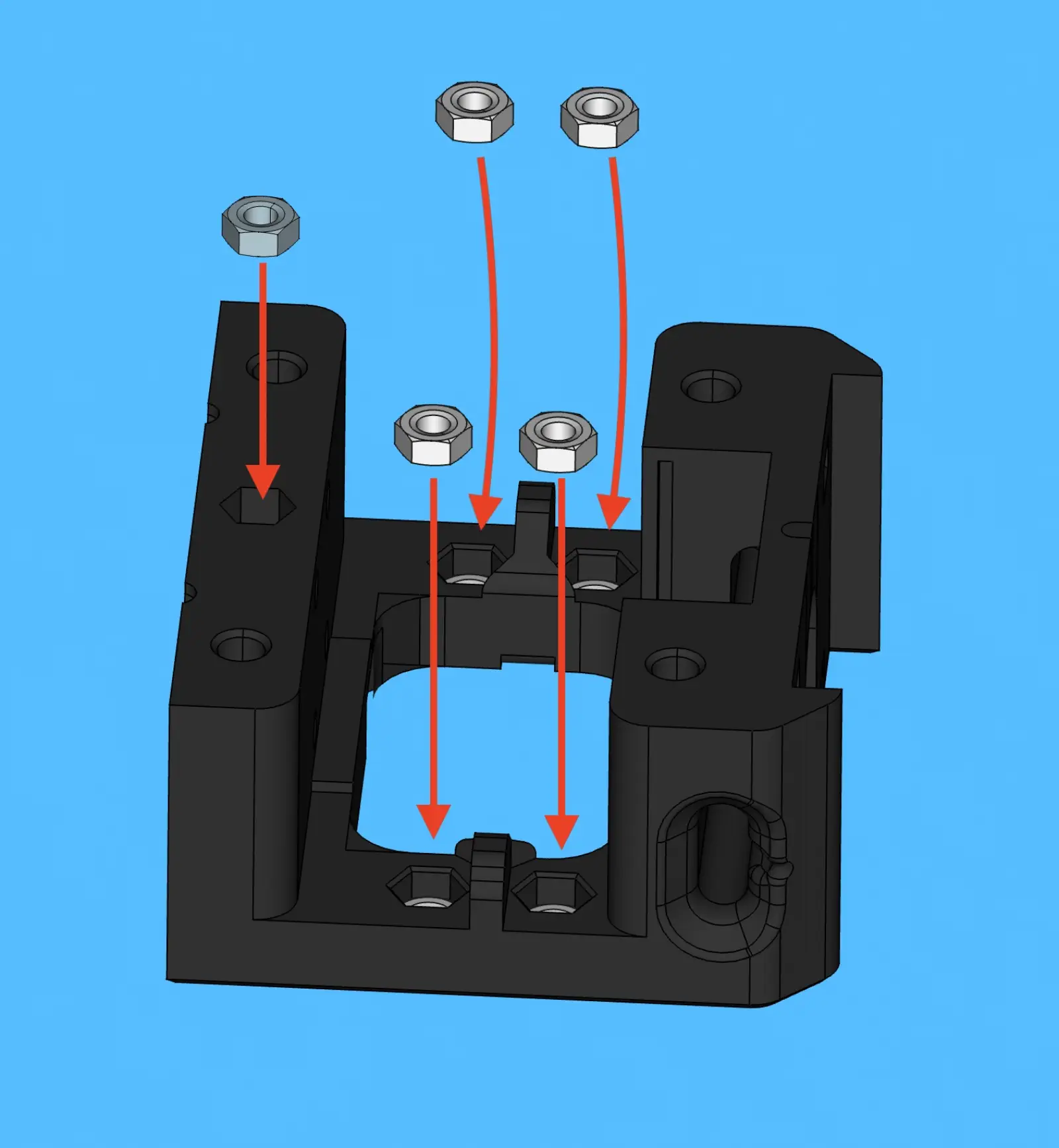
Step 2 of 37
Install frontside fasteners
-
Insert 5x
m5-hex-nutinto the following region
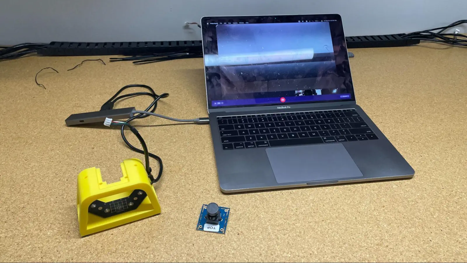
Step 3 of 37
Prep for top camera focus
-
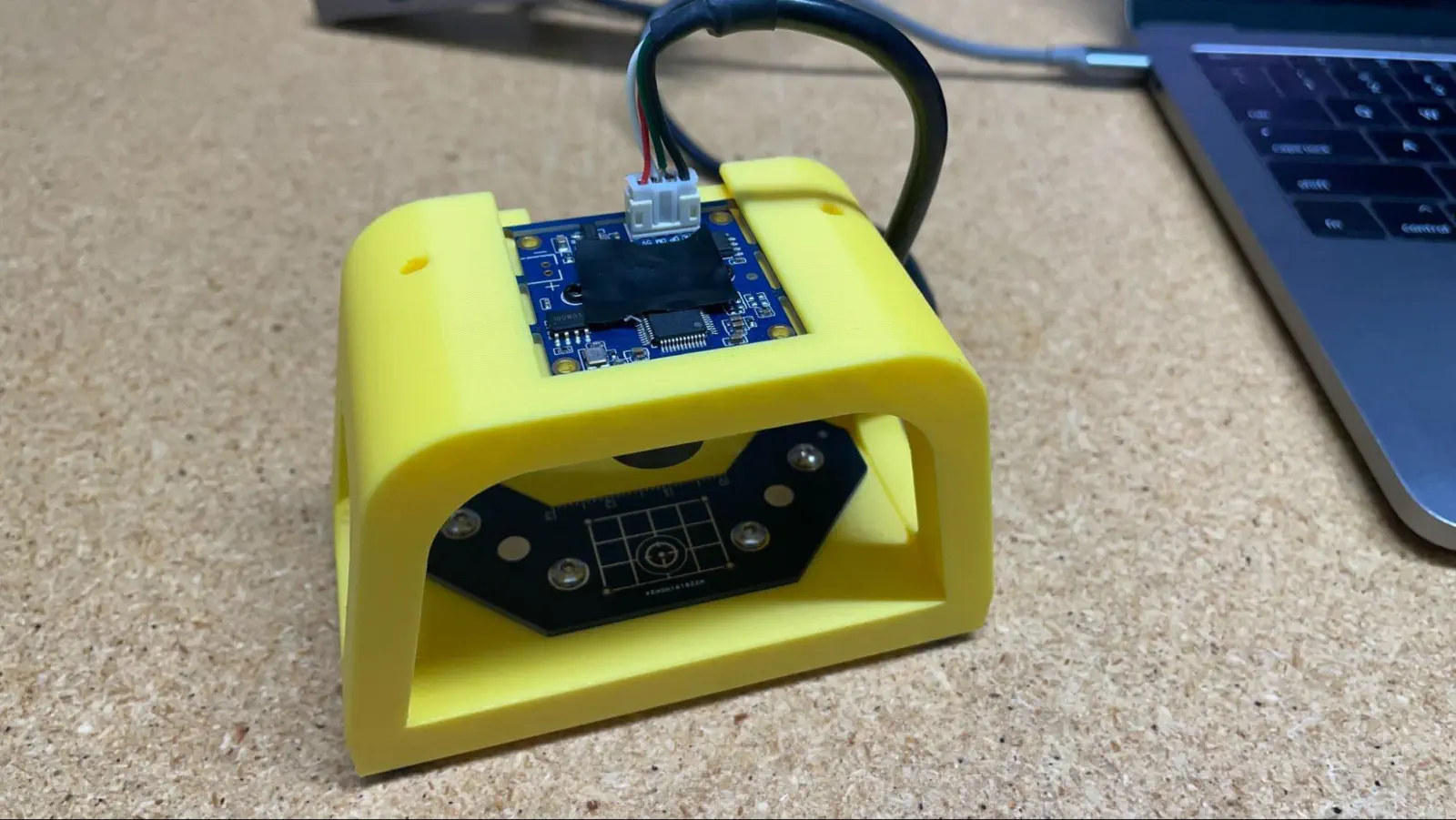
Acquire
top-camera-focus-jigand connecttop-camera-focus-jigto a laptop and open a native camera viewing application -
Remove
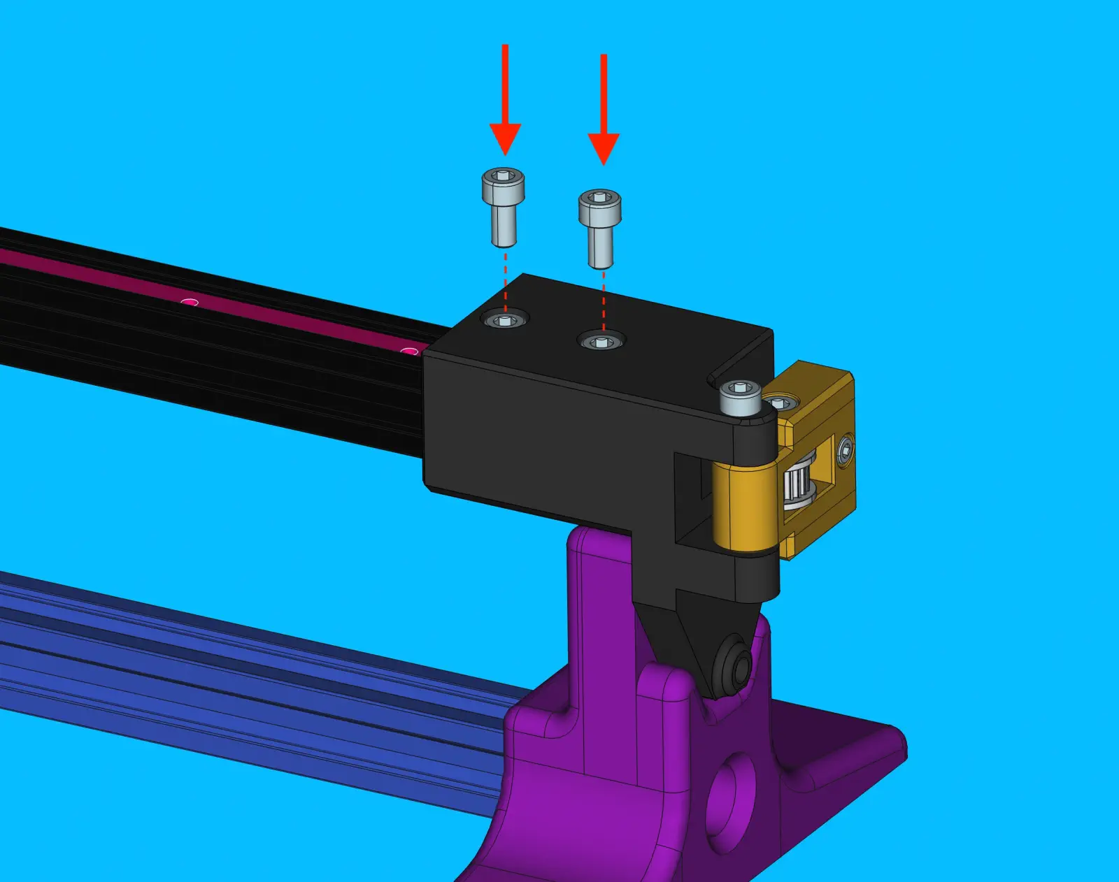
lens-capfromtop-camera -
Install the
top-camerafully into thetop-camera-focus-jig, plugging the USB cable into the camera module afterwards
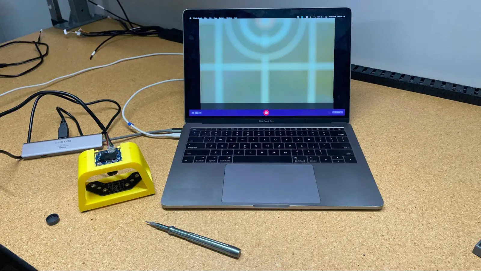


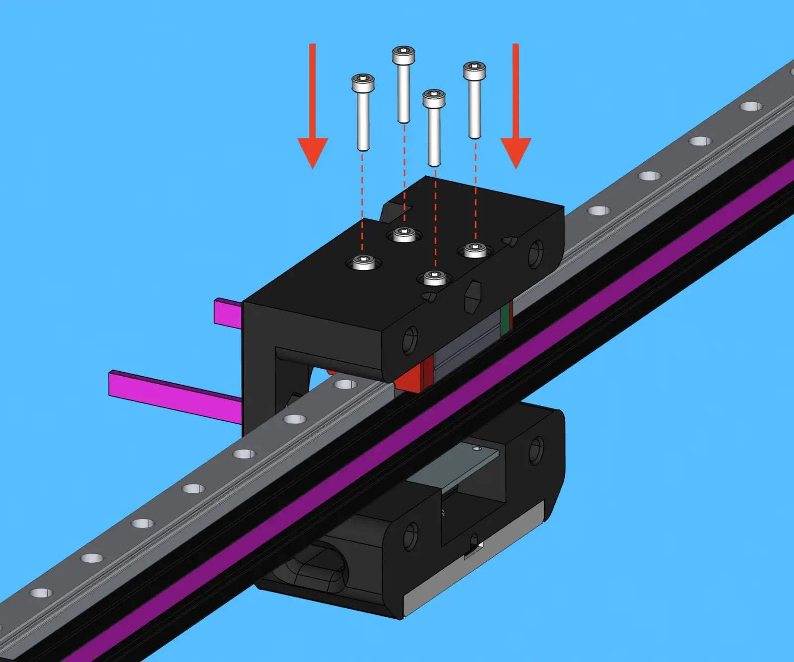
Step 4 of 37
Inspect the image and adjust
-
In Photo Booth, change the selected camera to
LumenPnP Topto view the camera feed fromtop-camera -
Rotate camera lens until live view shows
datum-boardas focused as possible
Step 5 of 37
Remove Camera and Replace Cover
- Remove the
top-camerafromtop-camera-focus-jigand immediately replacelens-cap
Step 6 of 37
Install Top Camera
-
Install
top-cameraintox-gantry-back
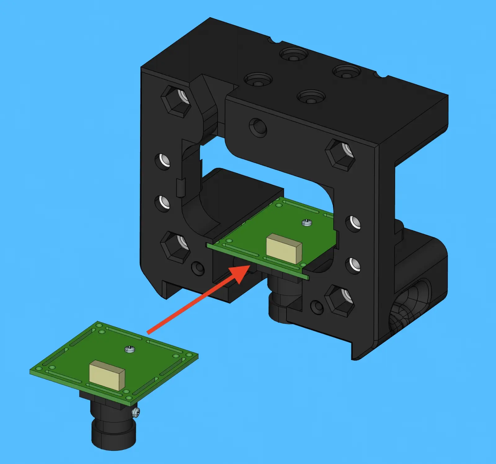
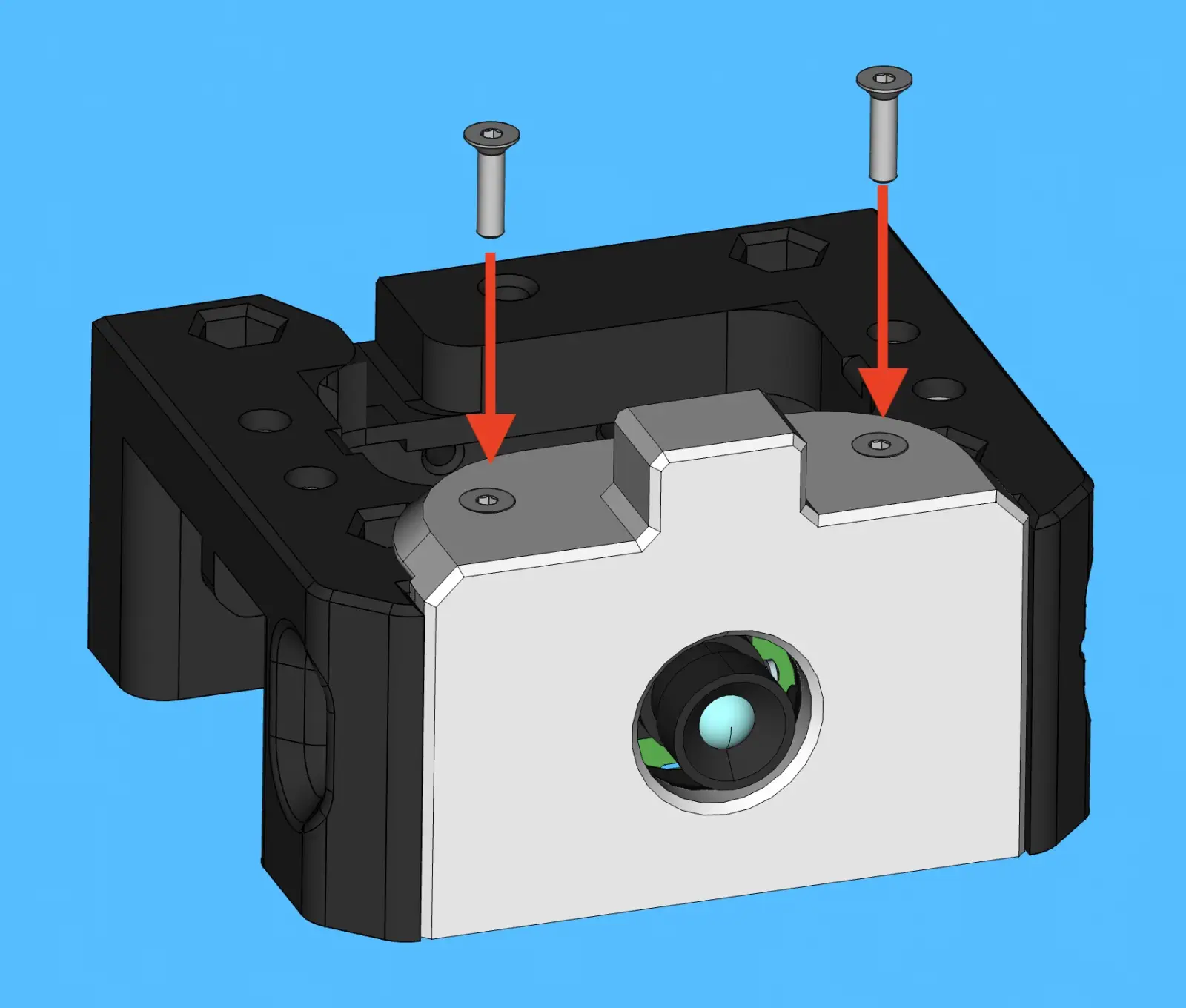
Step 7 of 37
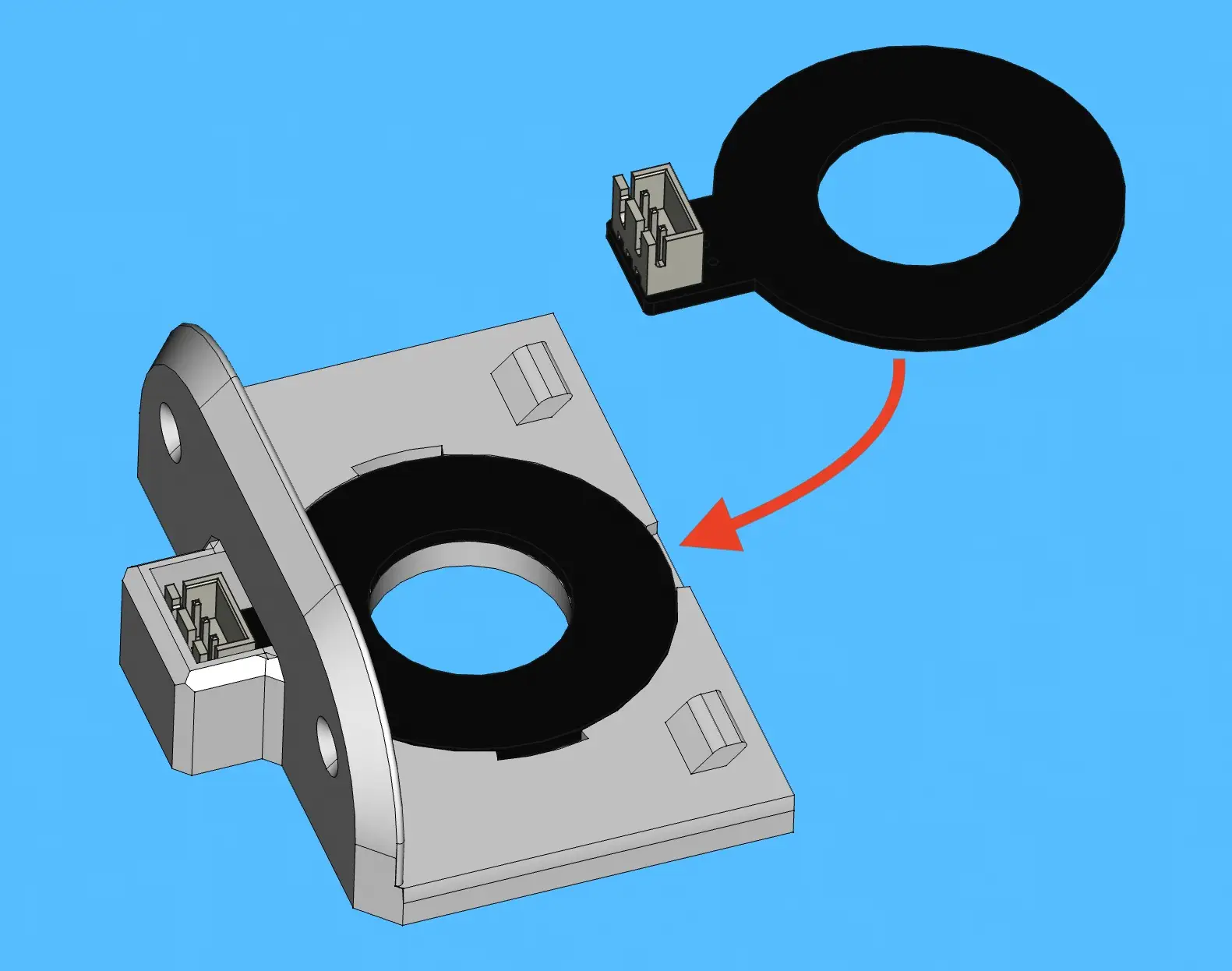
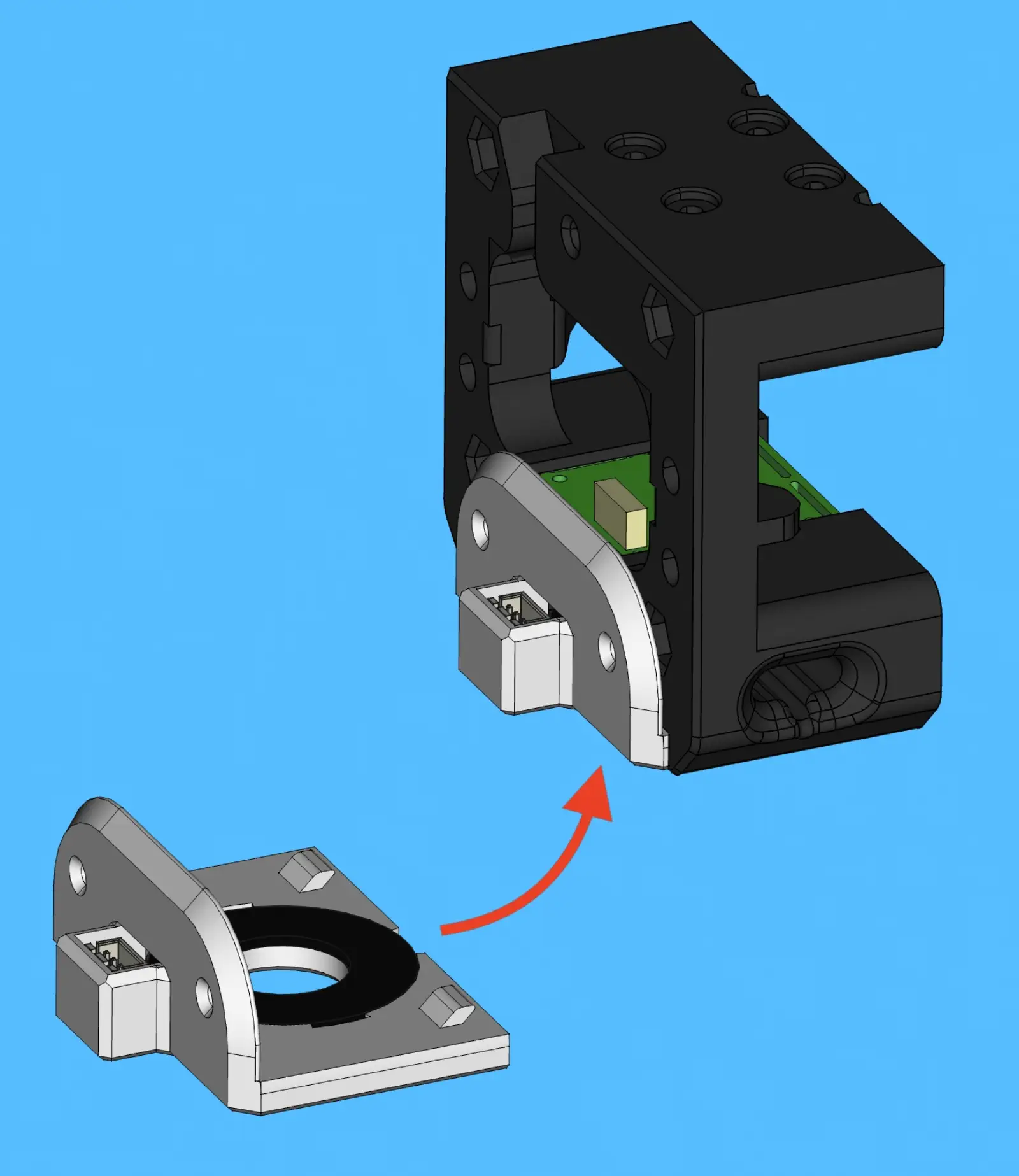
Install Top Light
-
Install
top-ring-lightintotop-light-mount -
Install
top-light-mountonto back ofx-gantry-back
Step 8 of 37
Secure Top Light
-
Secure
top-light-mountin place with 2xM3x12-self-tapping-flat-head
Step 9 of 37
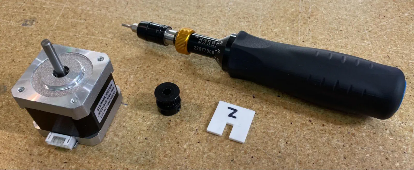
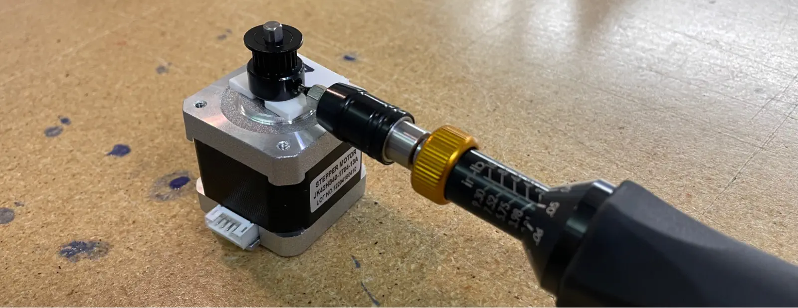
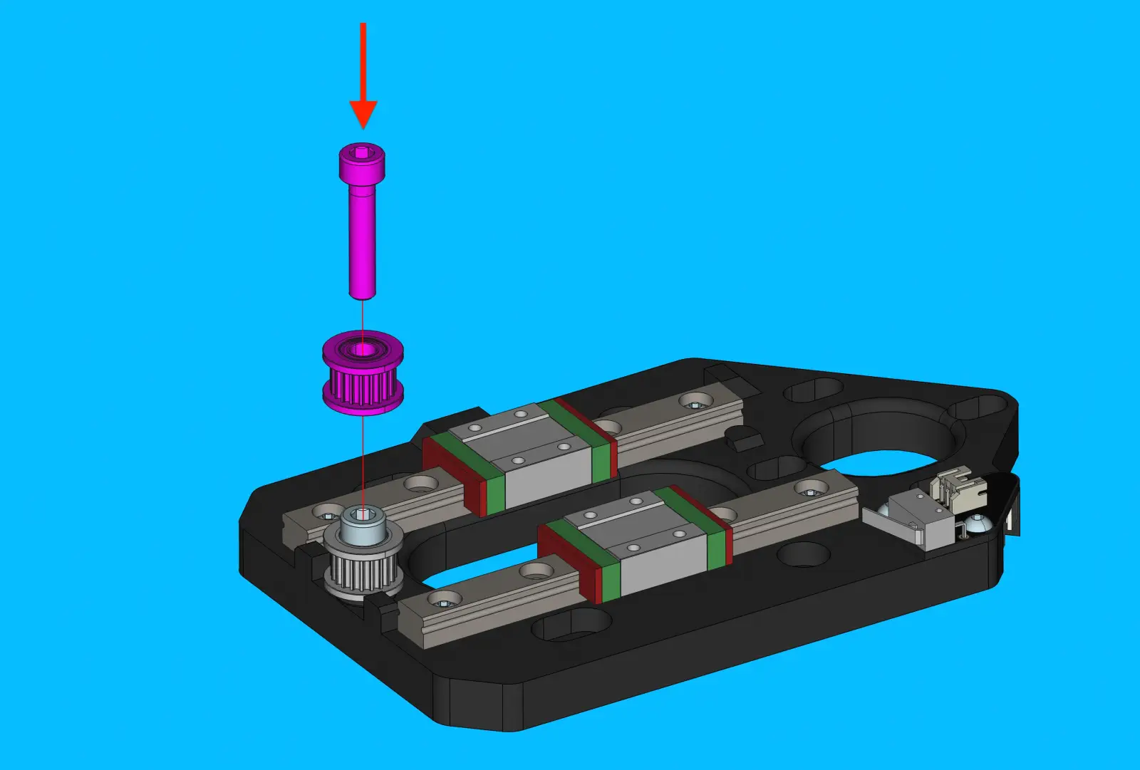
Prepare NEMA-17-stepper-motor for x-linear-axis
-
Set
timing-pulleyheight onNEMA-17-stepper-motorshaft withx-pulley-spacer-jig -
Tighten the first
set-screwinto the flat region found on theNEMA-17-stepper-motorshaft, before tightening the secondset-screw -
Tighten each
set-screwto 0.5 N/M
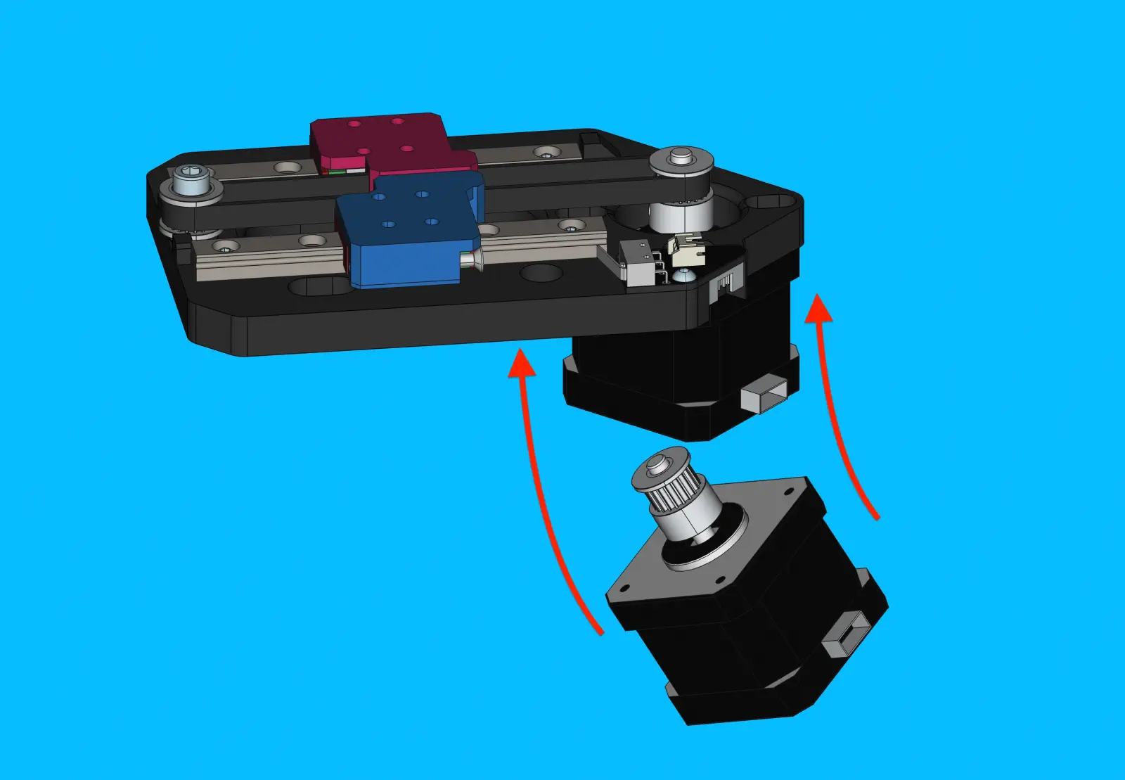
Step 10 of 37
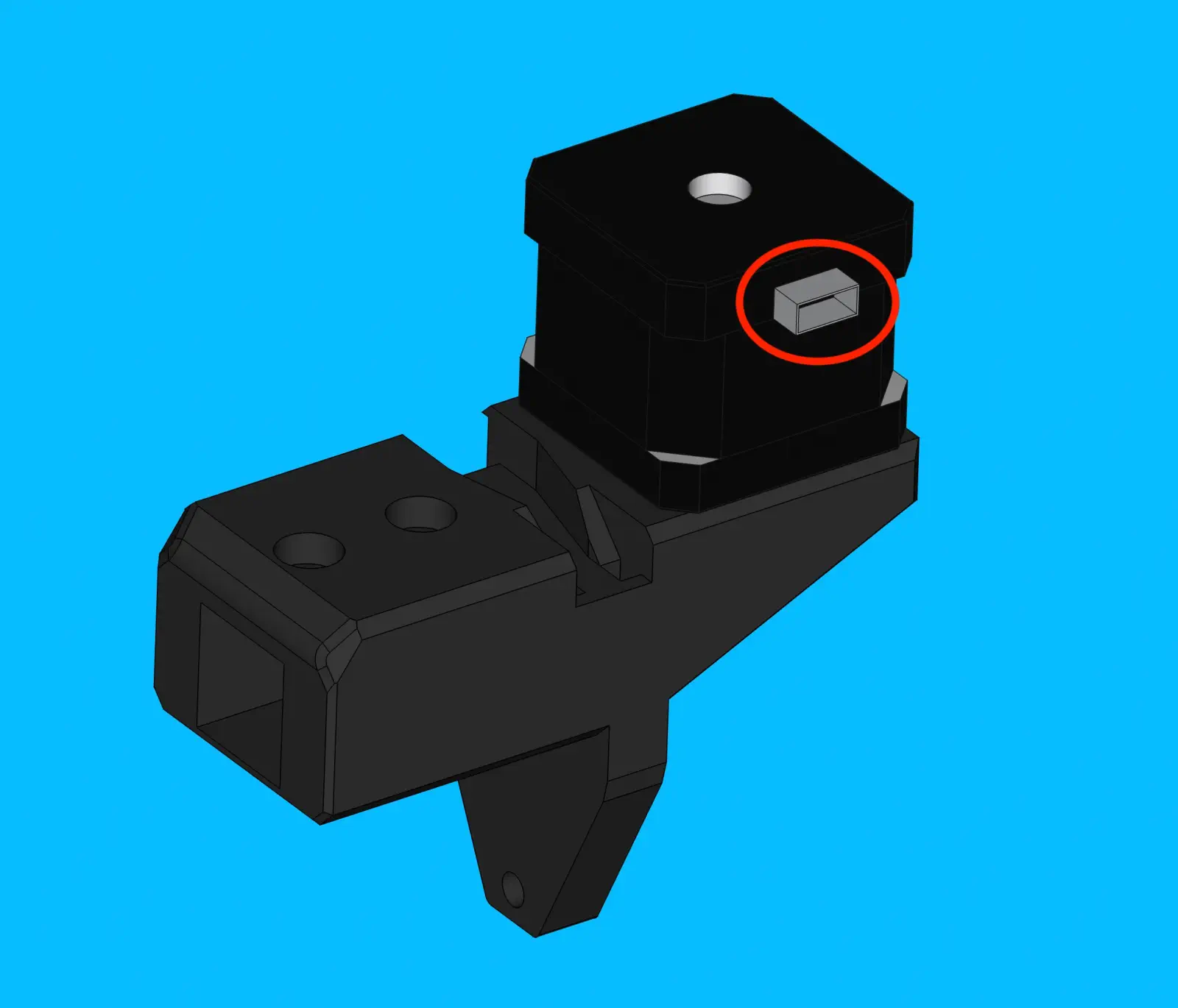
Install NEMA-17-stepper-motor onto x-motor-mount
-
Orient
NEMA-17-stepper-motorontox-motor-mountso that the motor's connector is facing the backside of the print as shown in the image -
Bolt
NEMA-17-stepper-motoronto x-motor-mountwith 4xM3x8-boltTorque Spec
Tighten these bolts to 0.5 N/M
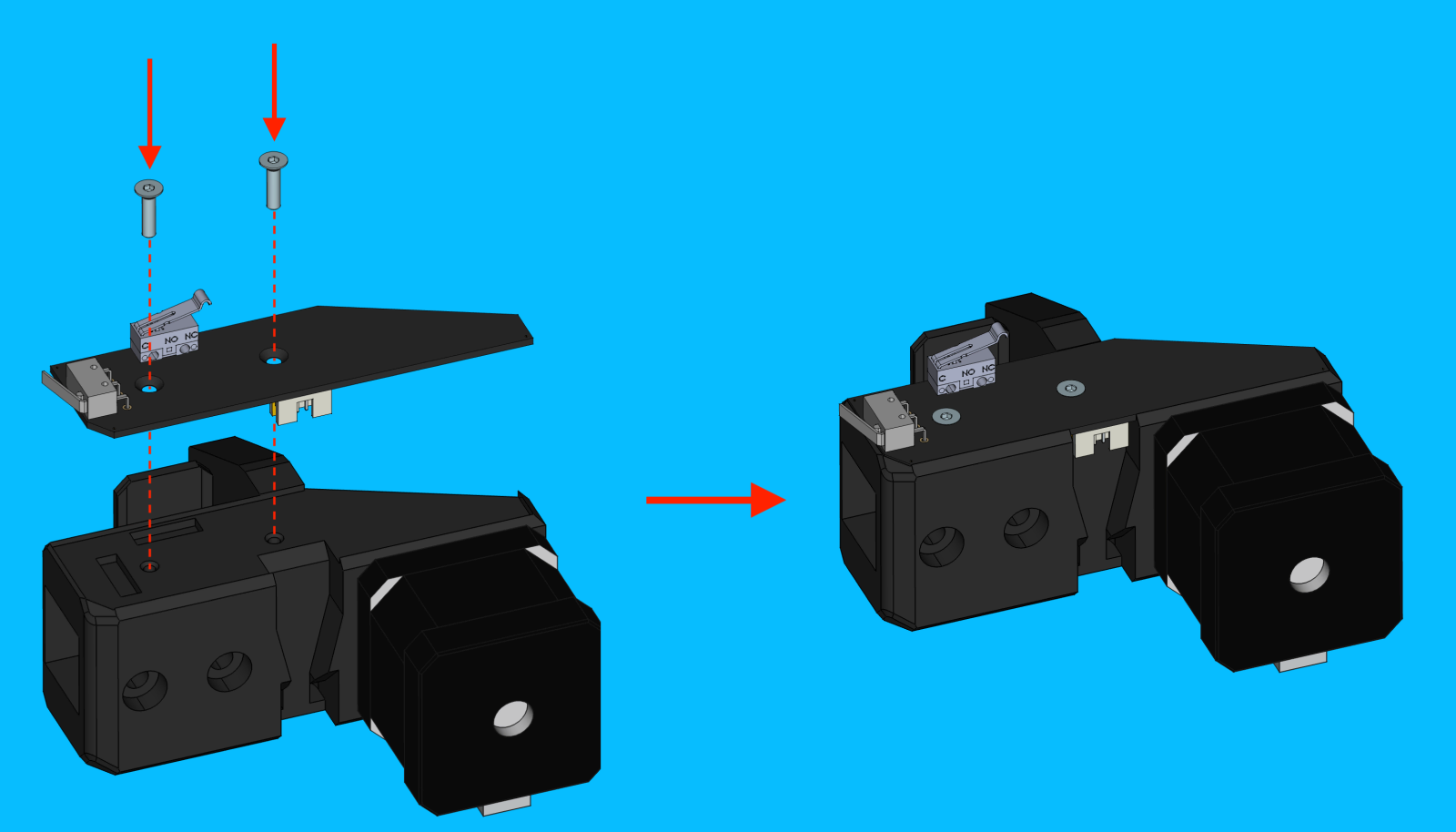
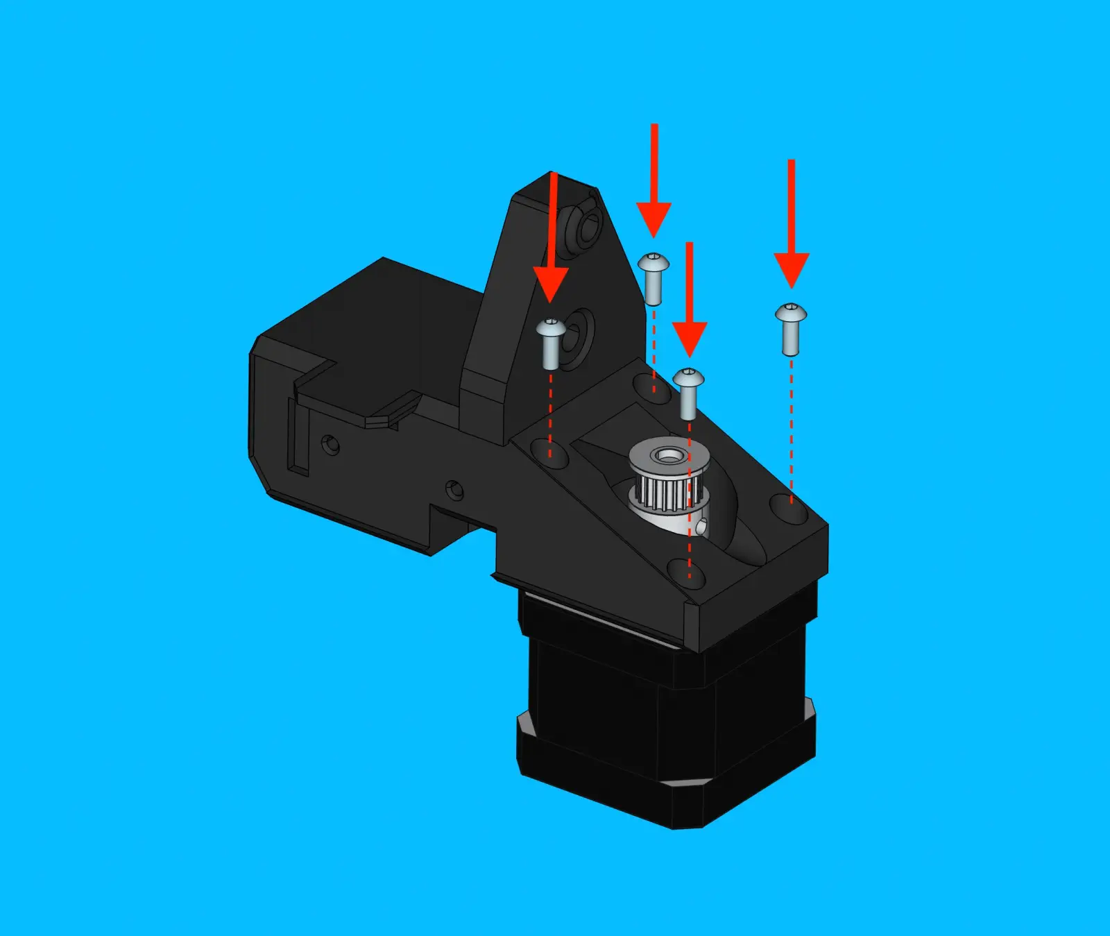
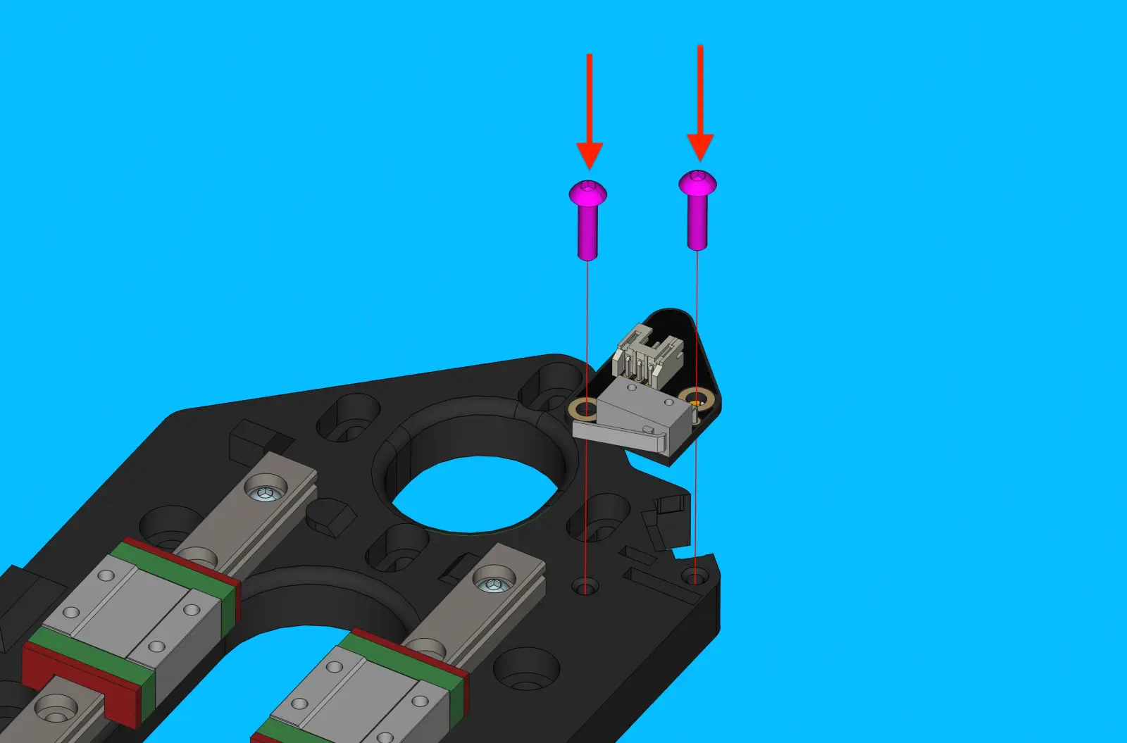
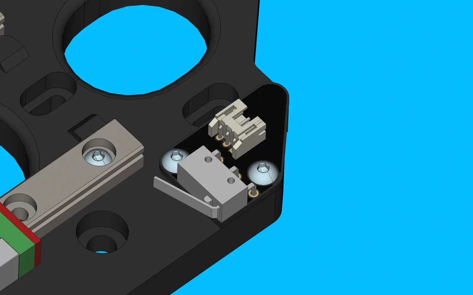
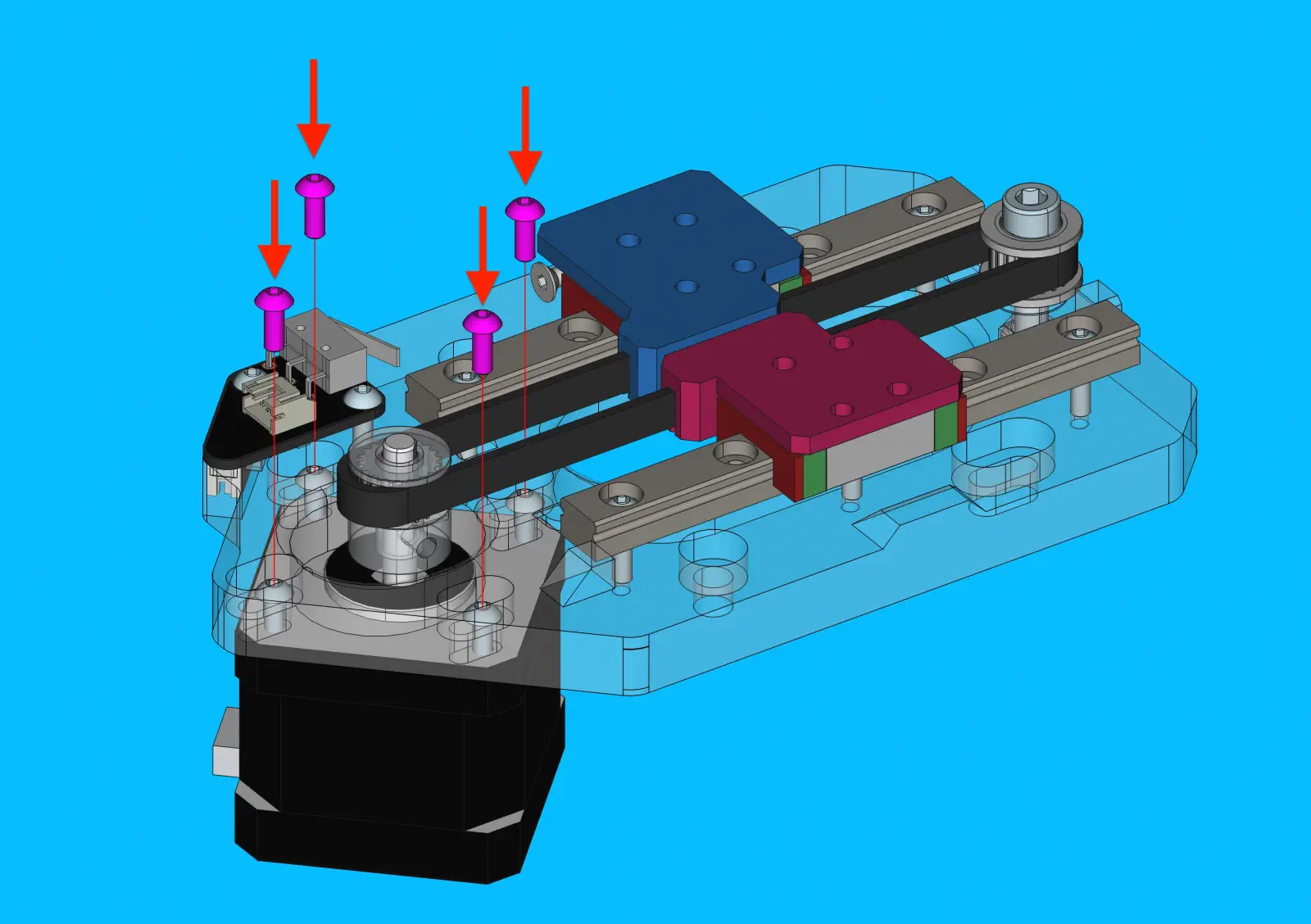
Step 11 of 37
Install XY-limit-switch-board onto x-motor-mount
-
Install
XY-limit-switch-boardontox-motor-mountand secure it with 2xM3x8mm-self-tapping-flat-head-screw -
Tighten each screw in place with the electic torque driver
-
If needed, clipping the ends off the pins of the right angle switch on
XY-limit-switch-boardhelps the pcb sit flat against the print.
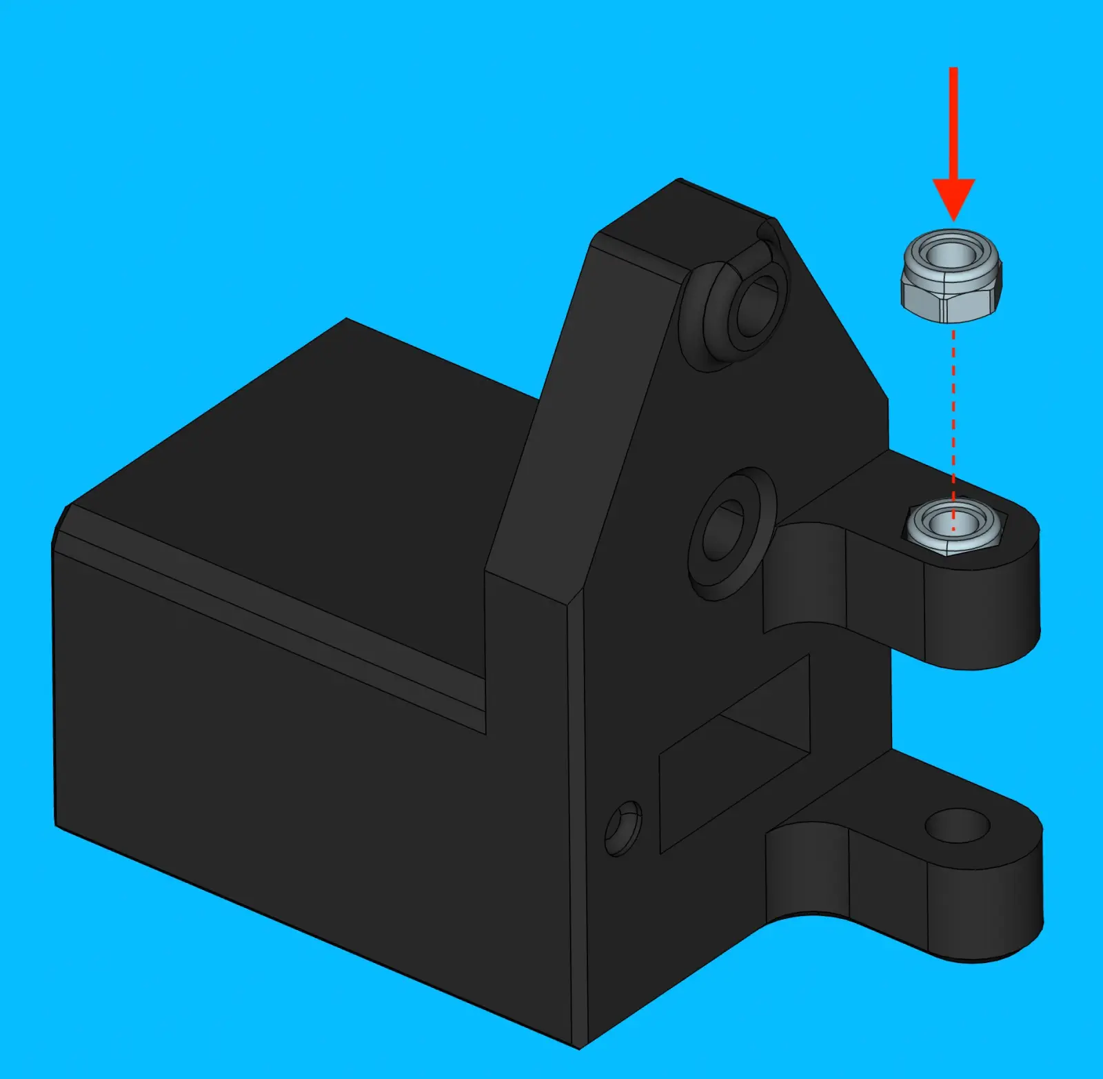
Step 12 of 37
Install nut into into x-idler mount
-
Install 1x
M5-lock-nutintox-idler-mount
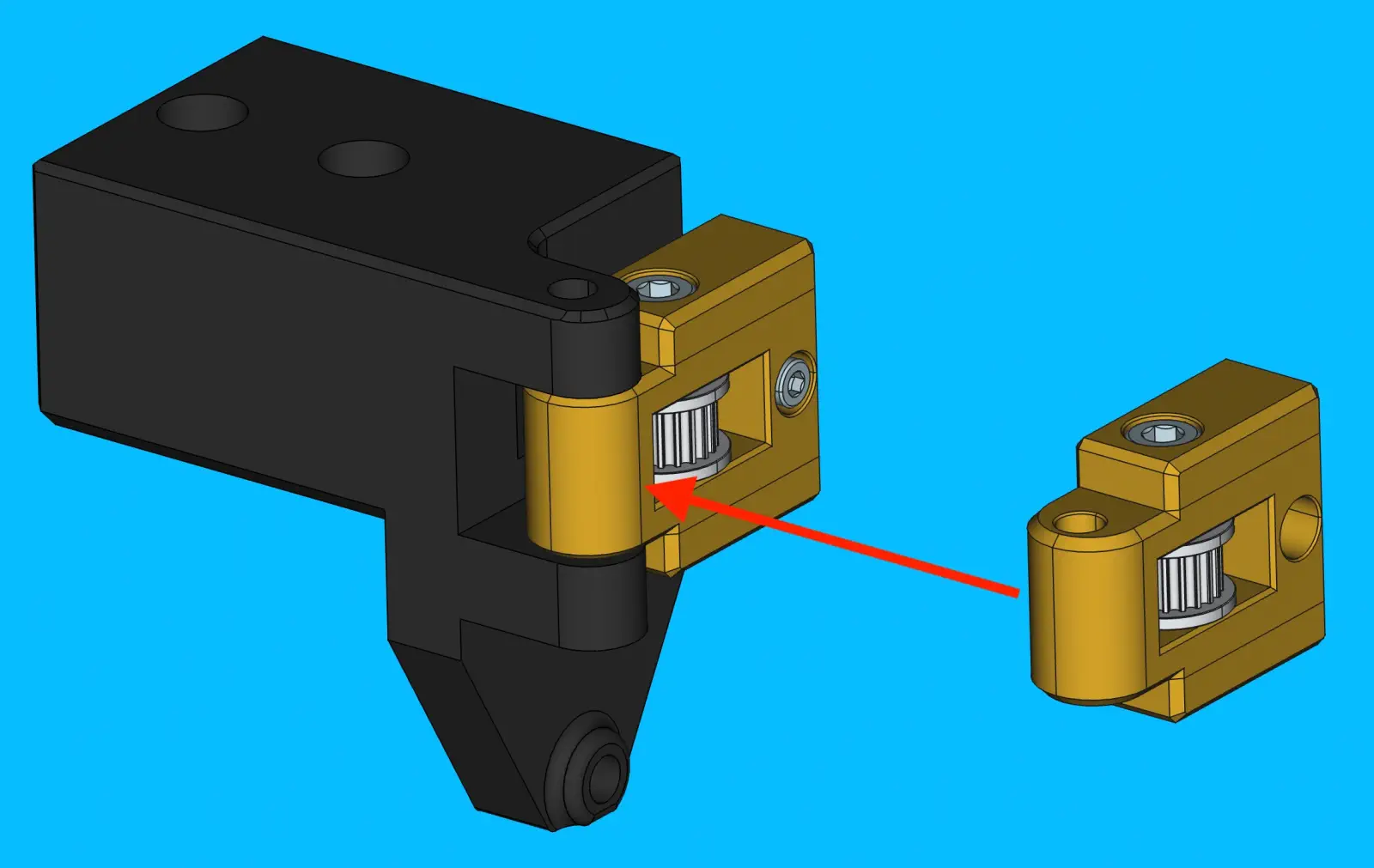
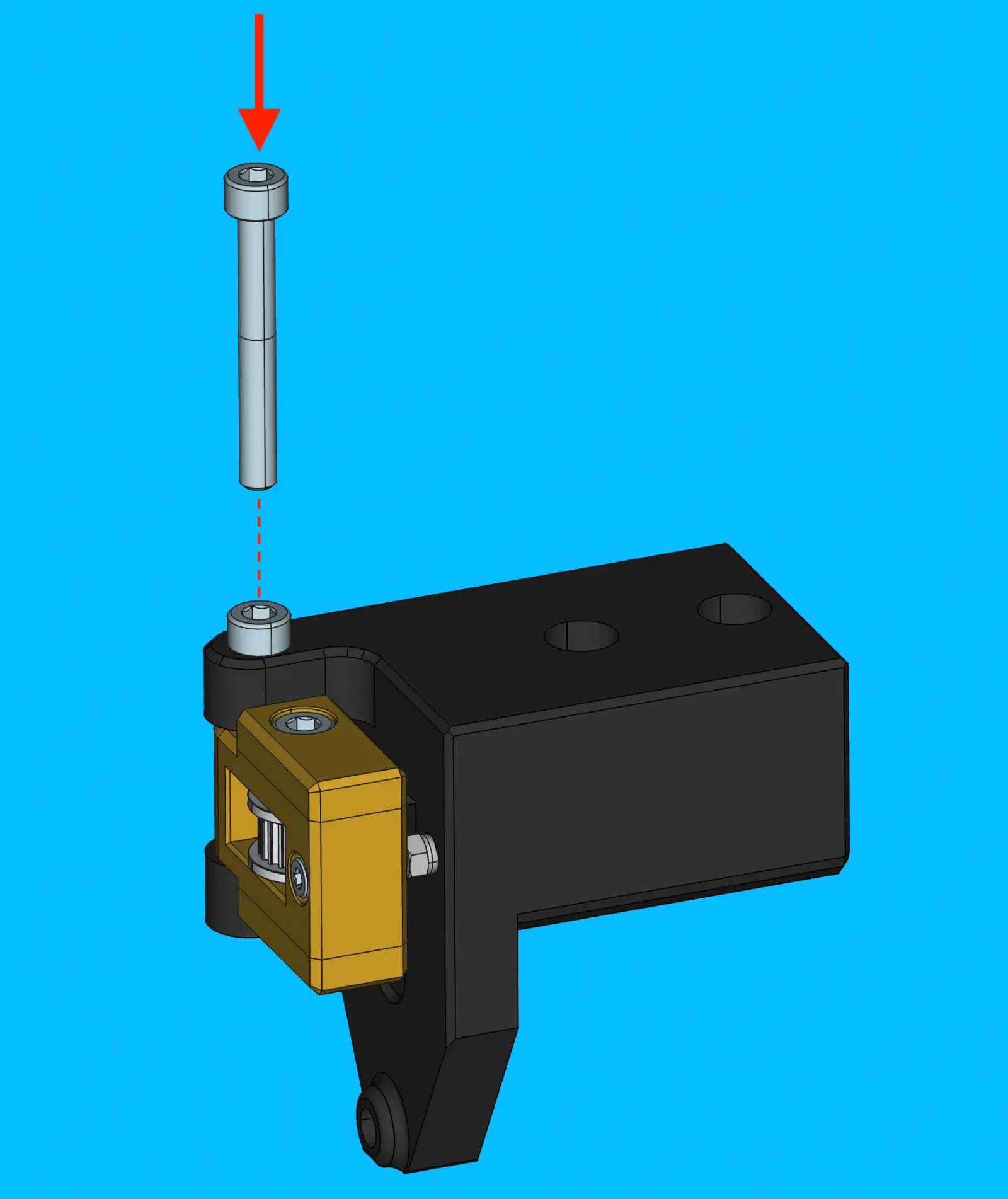
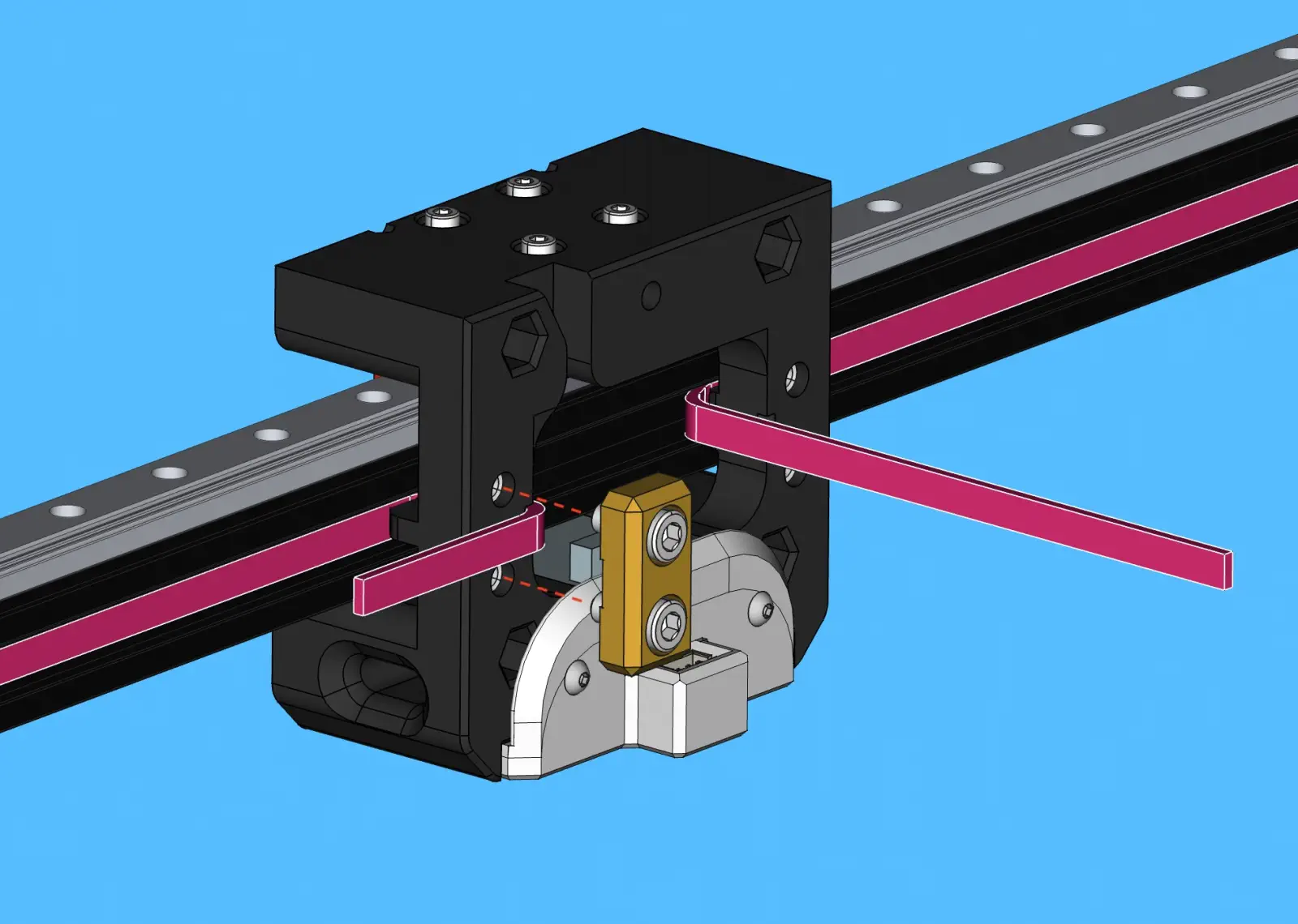
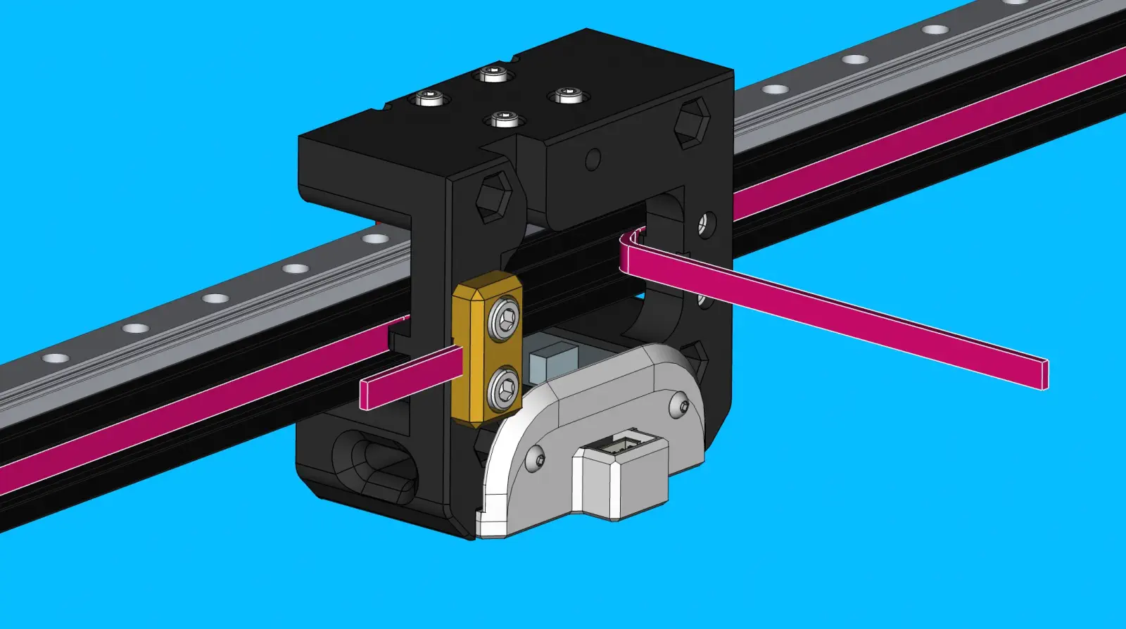
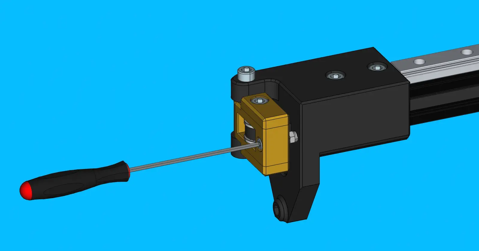
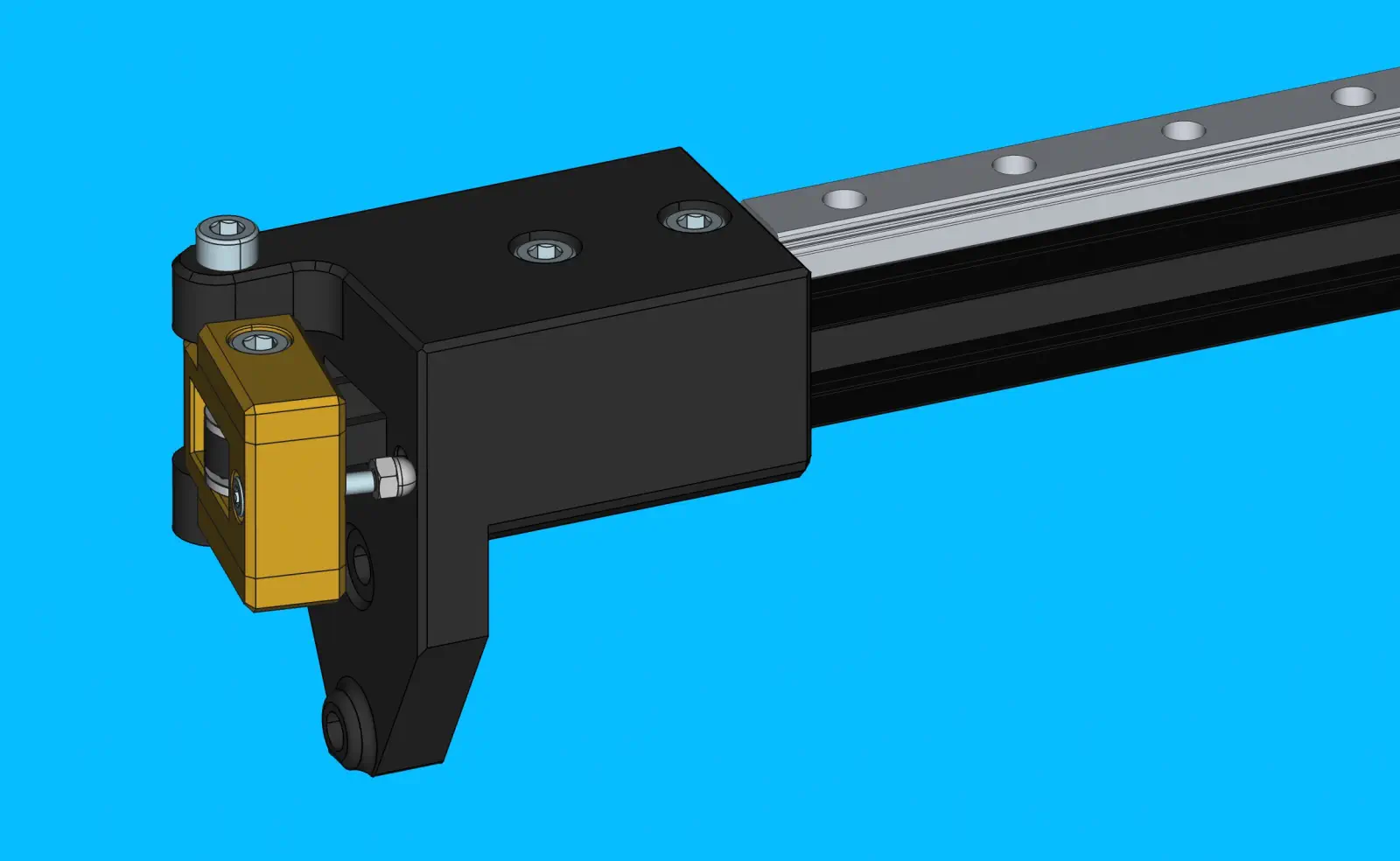
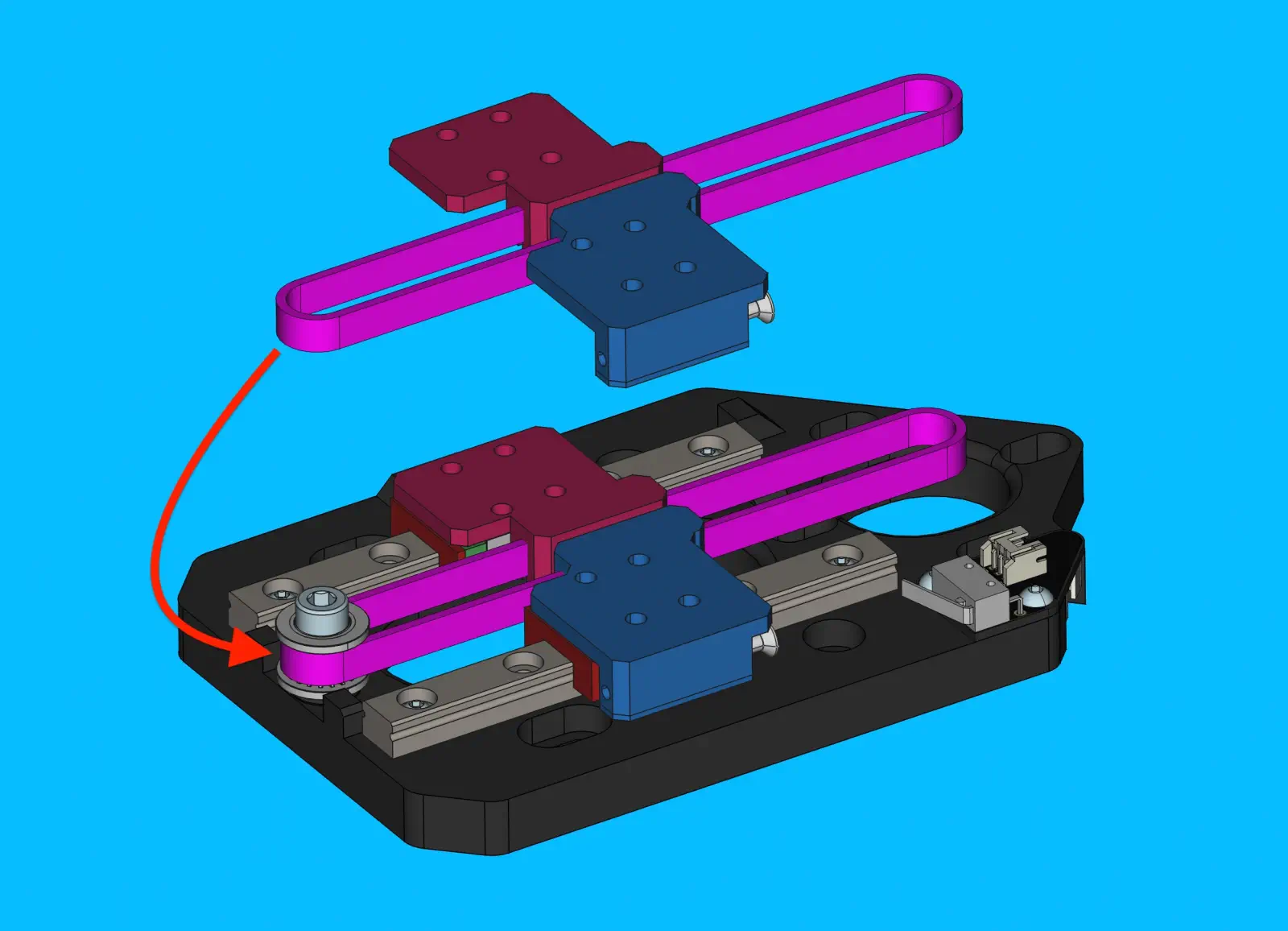
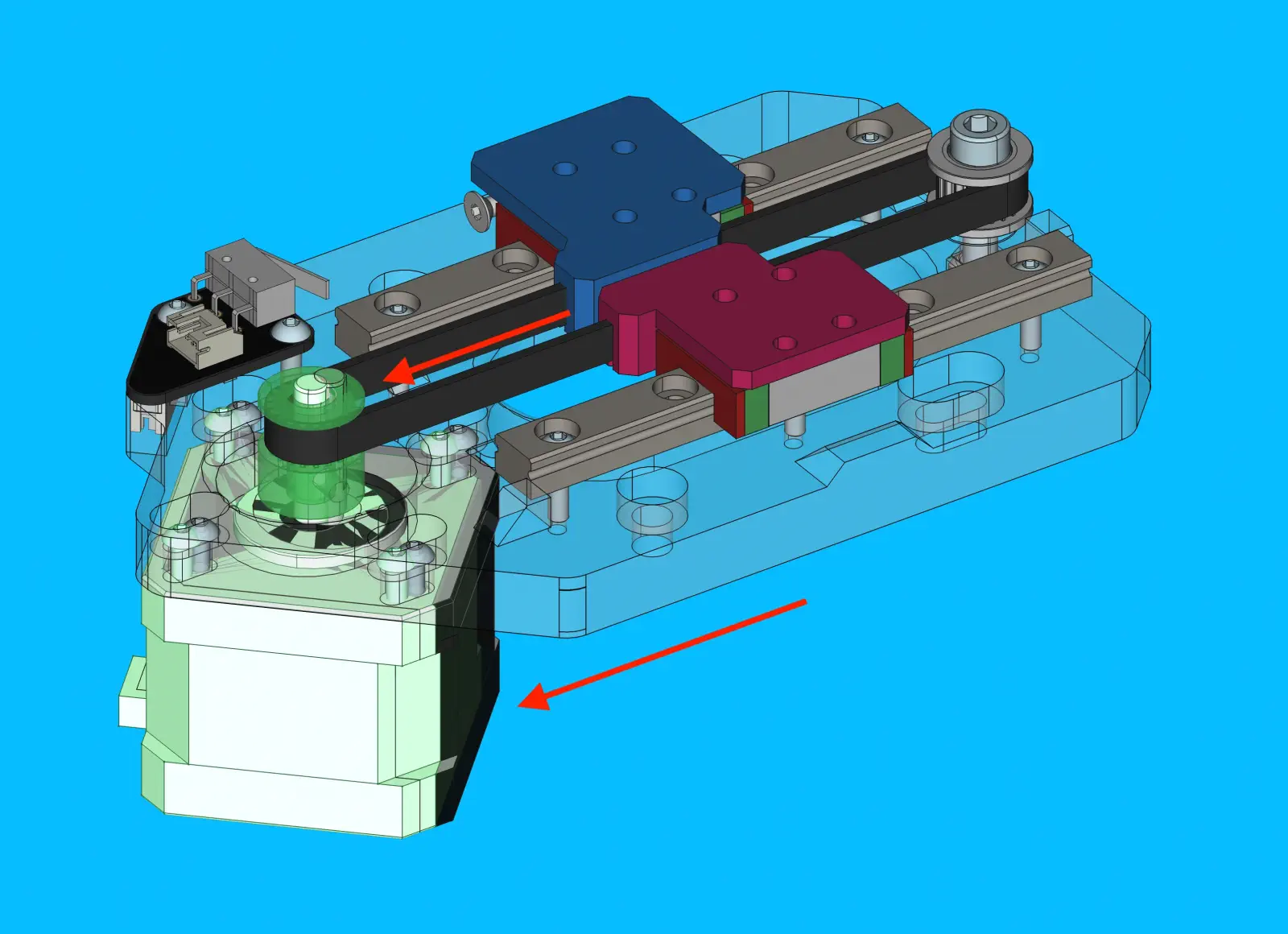
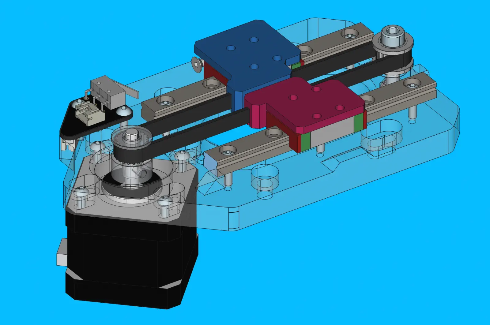
Step 13 of 37
Install Belt Tension Arm onto X Idler Mount
-
Install
belt-tensioner-armontox-idler-mountas shownInsert the correct direction
The acorn nut should be resting against the x-idler mount when installed correctly
-
Bolt
belt-tensioner-armtox-idler-mountwith 1xM5x40-socket-head-boltDon't Overtighten
belt-tensioner-armshould be able to pivot smoothly without much resistance.
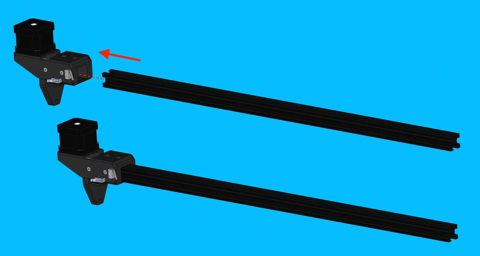
Step 14 of 37
Install alu-extrusion onto x-motor-mount
-
Insert
alu-extrusionintox-idler-mount, using light force as necessary -
Insert 2x
M5-t-nutintoalu-extrusion -
Secure
alu-extrusionin place with 2xM5x10-socket-head-boltTorque Spec
Tighten these bolts to 0.5 N/M
Step 15 of 37
Install M3-t-nut-bar
Inspect the M3-t-nut-bar to ensure that each hole has M3 threads
-
Slide
M3-t-nut-barinto top-side track ofalu-extrusion
Step 16 of 37
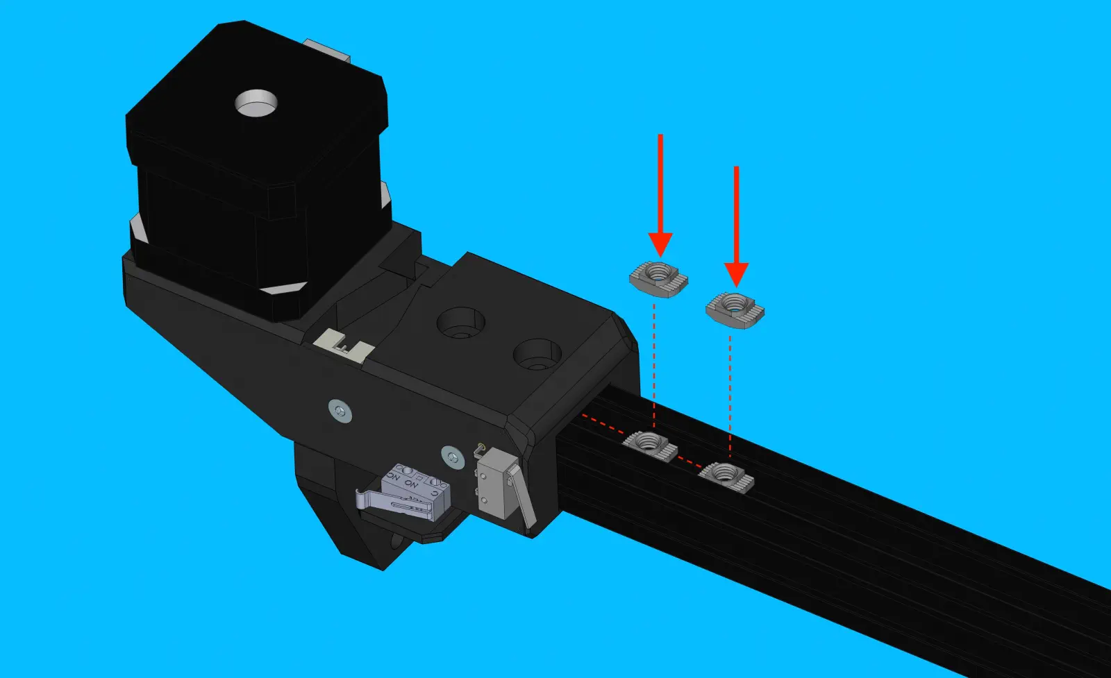
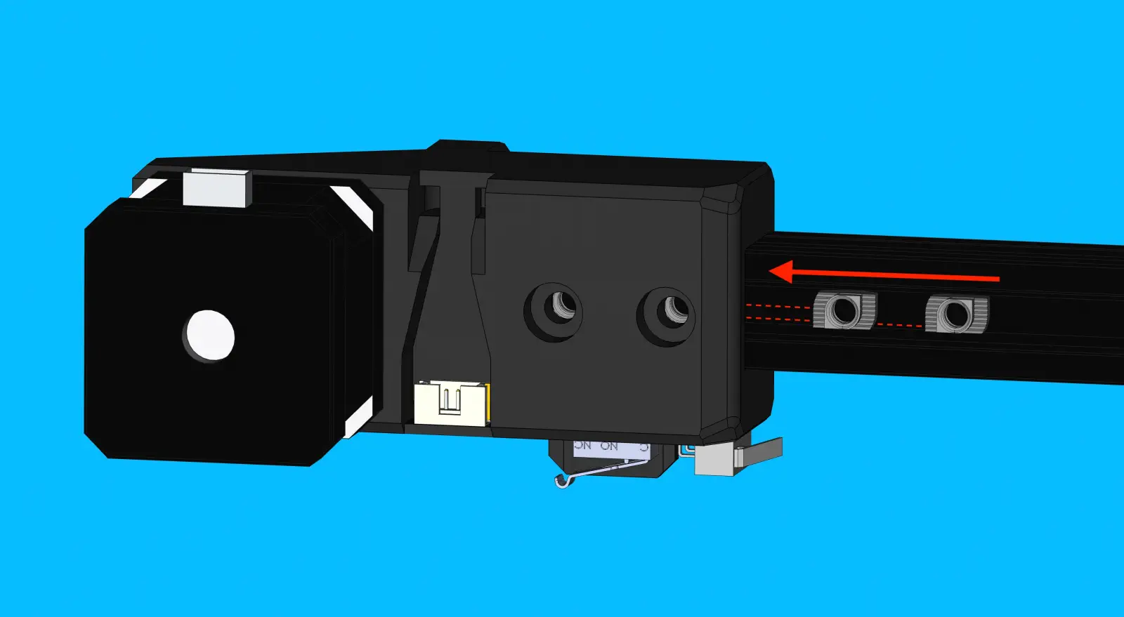
Install x-idler-mount onto alu-extrusion
-
Insert 2x
M5-t-nutintoalu-extrusion -
Slide
x-idler-mountontoalu-extrusion
Step 17 of 37
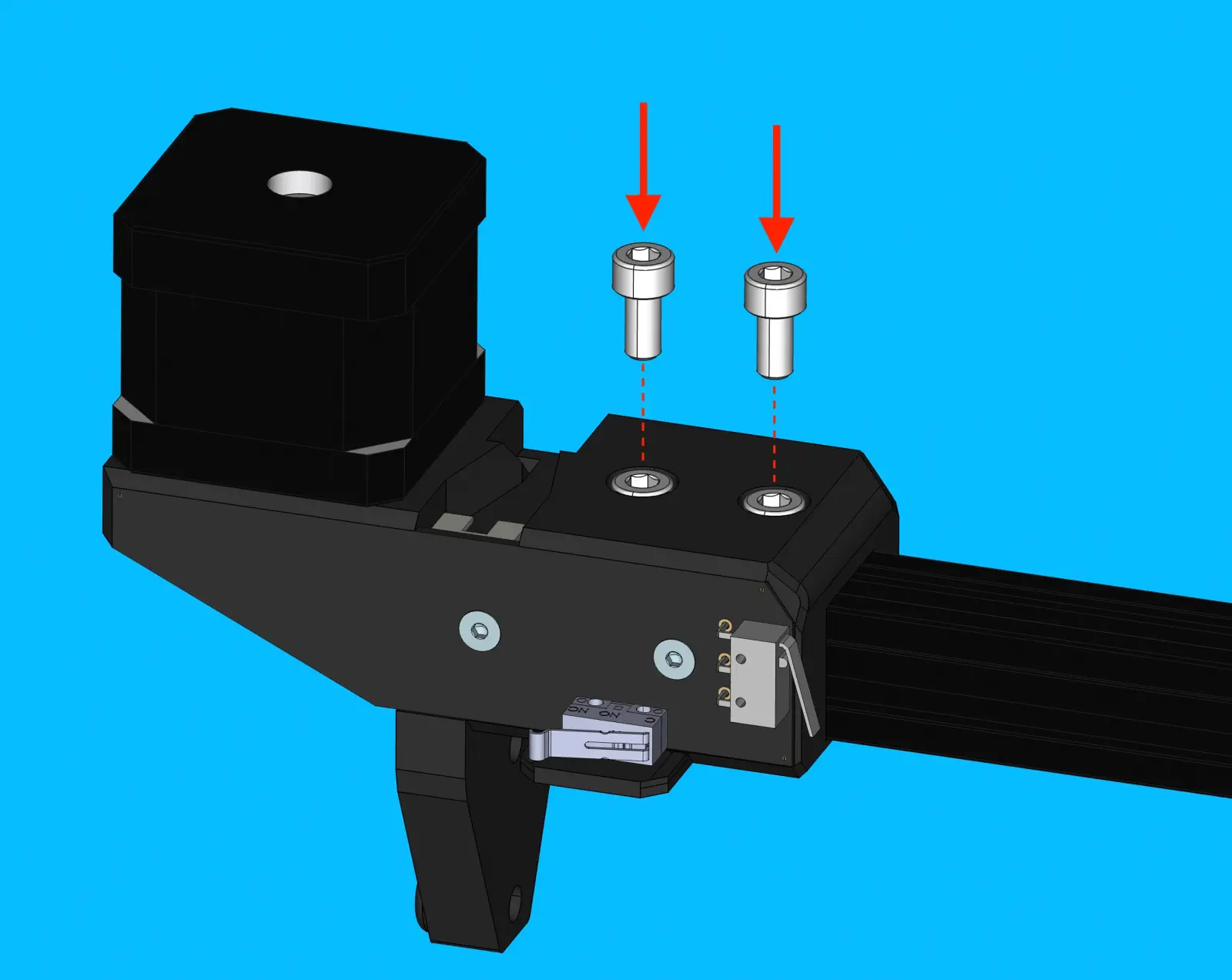
Secure X Gantry Spacing
-
Use
x-gantry-spacer-jigto slidex-idler-mountontoalu-extrusion. Thex-linear-axisshould be sitting onx-gantry-spacer-jigsnug - not overly tight - whenx-idler-mountis at the correct depth -
Secure
x-idler-mountin place with 2xM5x10-socket-head-boltNote
Tighten these bolts to 0.5N/M
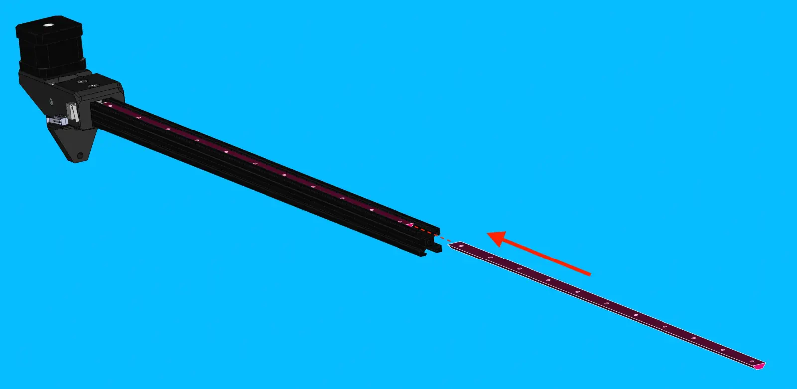
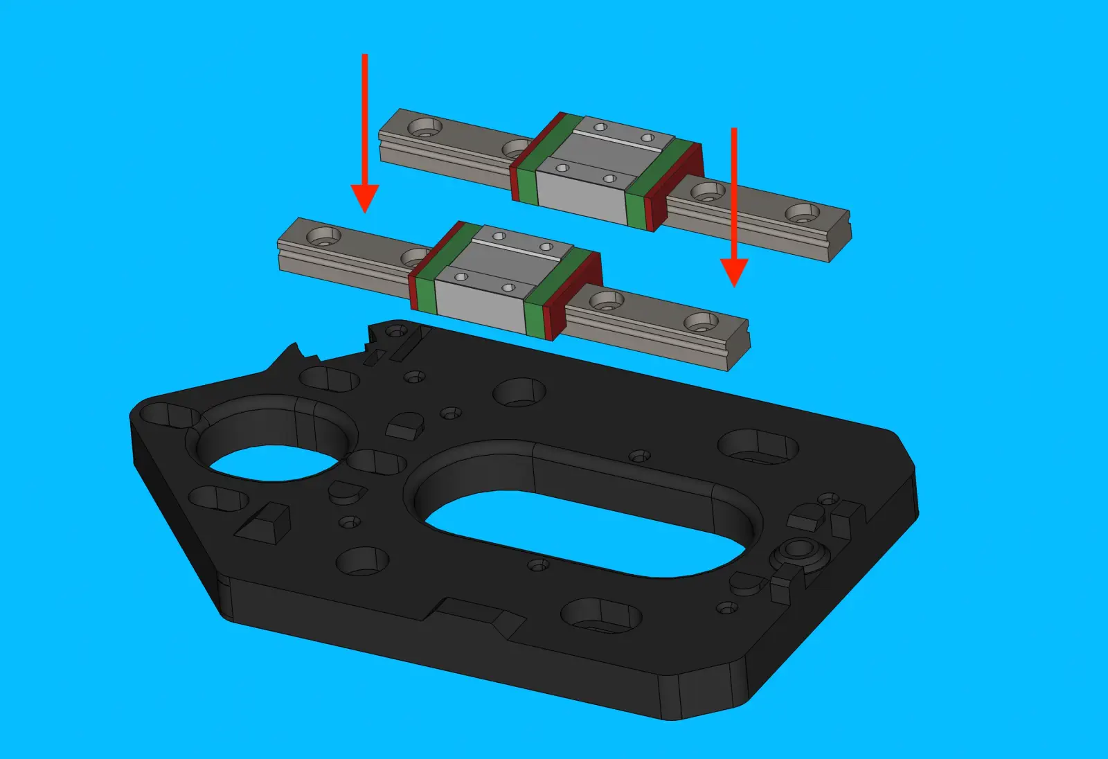
Step 18 of 37
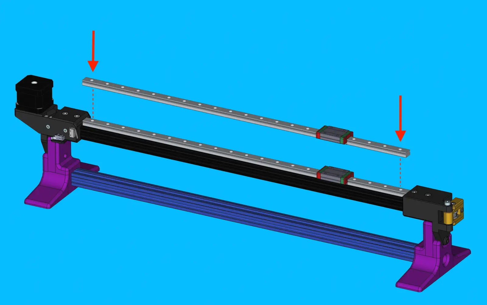
Align linear-rail-525mm
-
Roughly position
linear-rail-525mmonto top-side ofalu-extrusion -
Place a
linear-rail-2020-alignment-jigon both ends oflinear-rail-525mm. Do not cover any bolt holes with the jig -
Visually center
linear-rail-525mmbetweenx-motor-mountandx-idler-mount -
Slide the
M3-t-nut-barto line up with the rail's bolt hole pattern
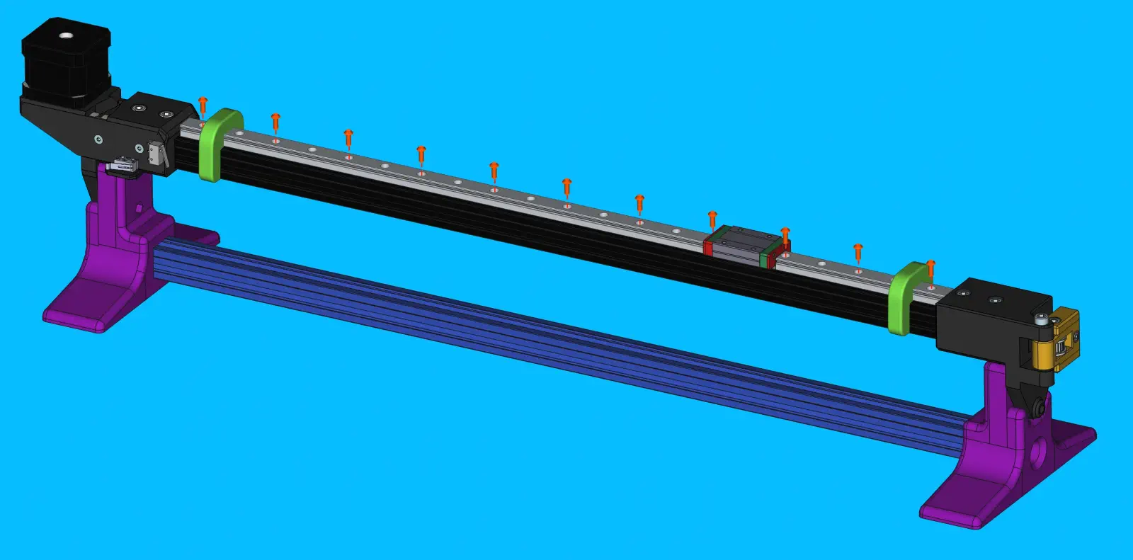
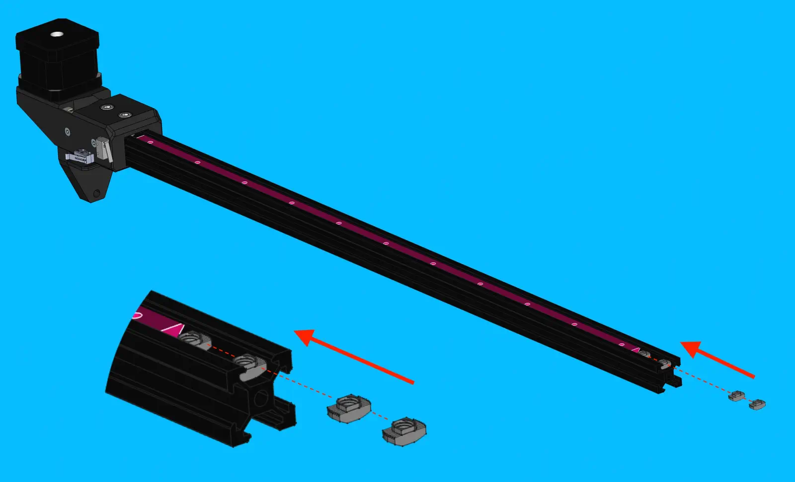
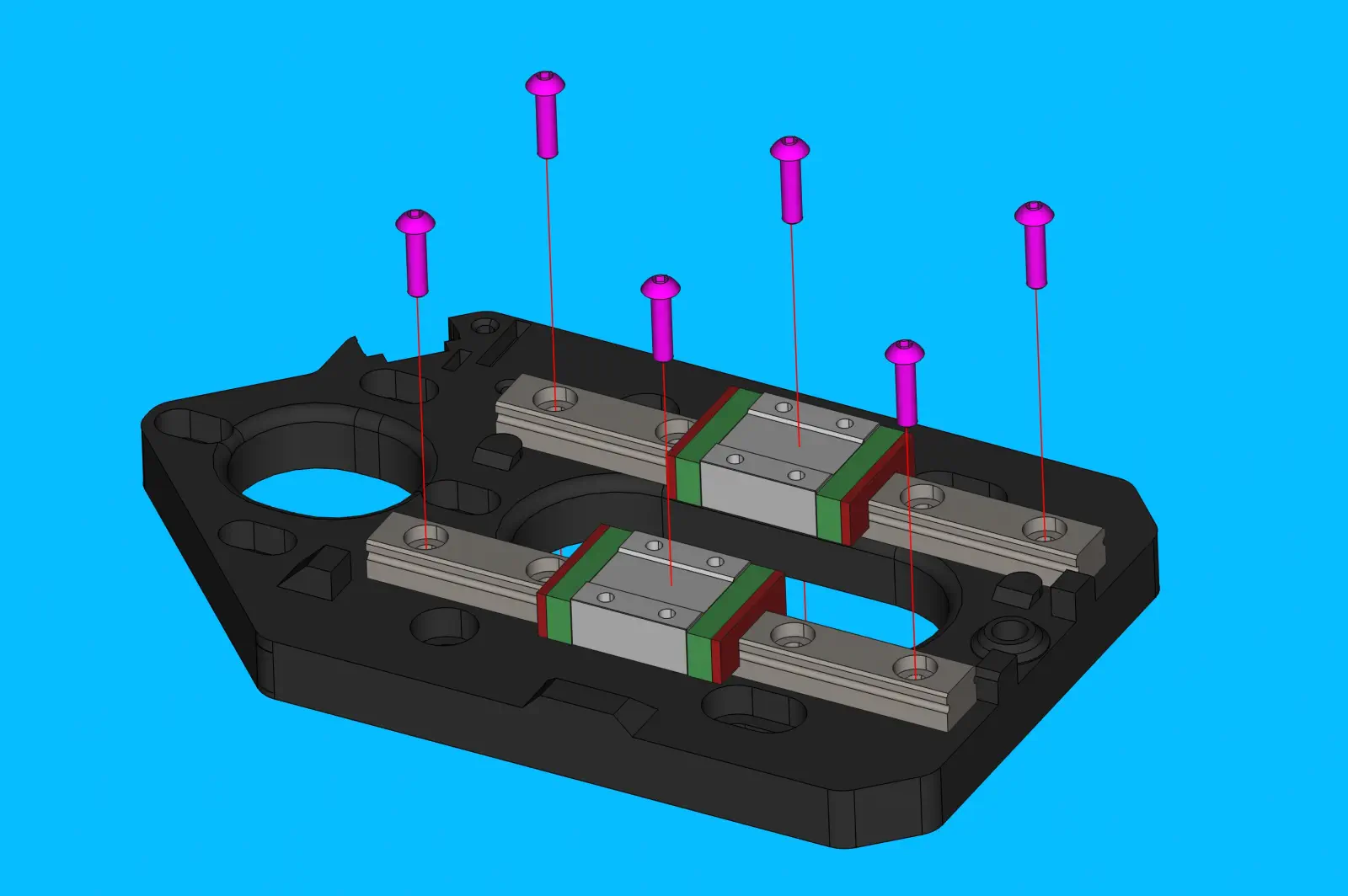
Step 19 of 37
Load Screws for the 525mm linear rail
-
Starting from the
x-motor-mountside, lightly snug aM3x8-boltinto every other bolt hole onlinear-rail-525mm -
Move the
linear-rail-carriageout of the way as needed
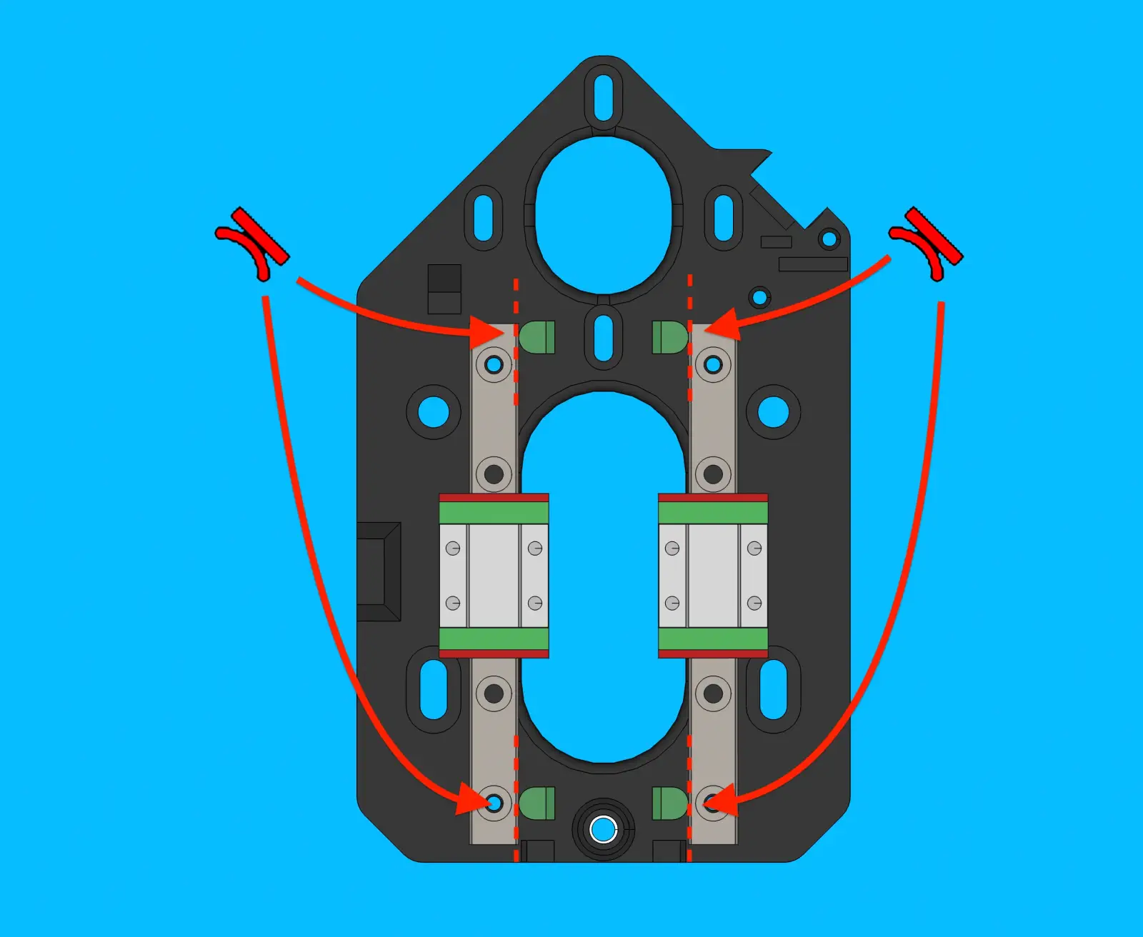
Step 20 of 37
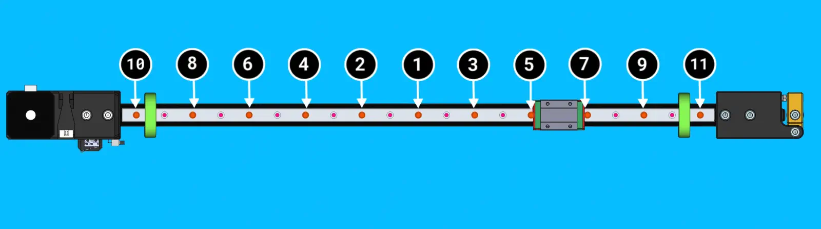
Attach the 525mm linear rail
-
Tighten the rail mounting bolts to in the sequence shown in the image, starting in the center.
Note
A torque wrench set to 0.5N/M must be used when tightening these bolts
Step 21 of 37
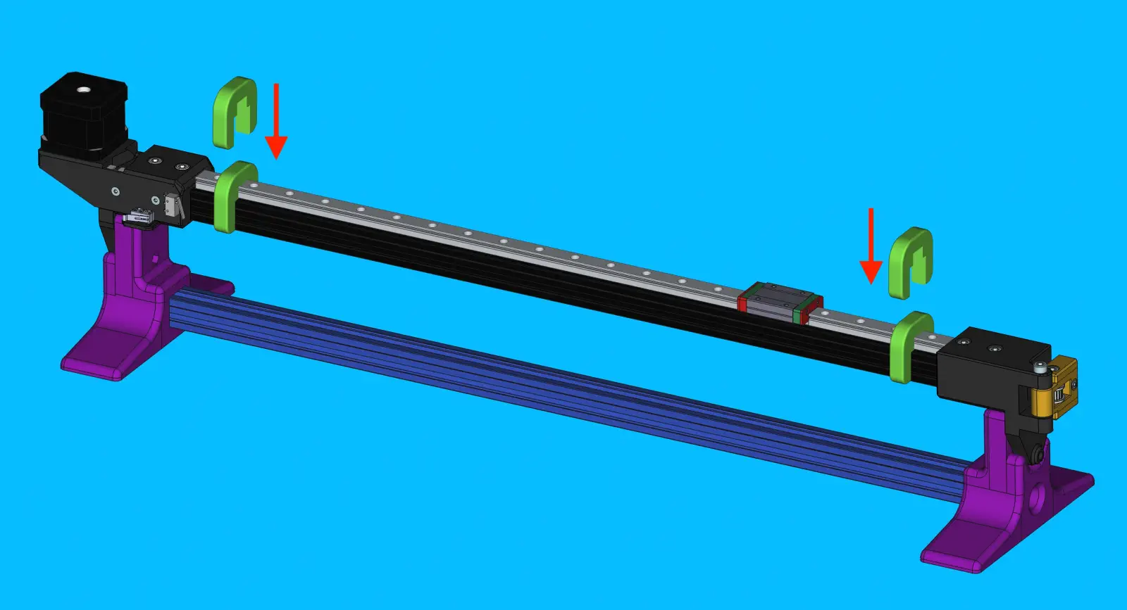
Remove the jigs and check movement
- Remove the
linear-rail-2020-alignment-jigfrom both ends oflinear-rail-525mm - Slide the
linear-rail-carriageback and forth a few times, checking to see that it travels smoothly and consistently
Step 22 of 37
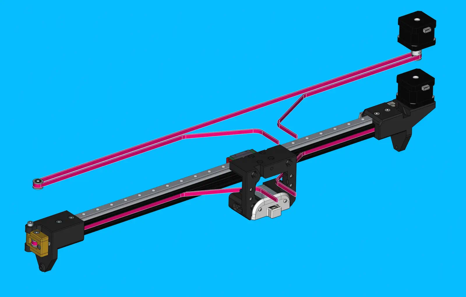
Install GT2-belt and x-gantry-back
-
Using a 1.5m-long piece of
GT2-belt:- Start by running the belt through the left-side slot on
x-gantry-backand leave 75mm of extra belt poking out - Run it through the extrusion towards the
x-motor-mount - Wrap it around the
timing-pulley - Run it back through the extrusion towards the
x-idler-mount - Wrap it around the
idler-pulley - Run it back through the extrusion towards the
x-motor-mountagain - Have the belt exit through the right-side slot on
x-gantry-back
- Start by running the belt through the left-side slot on
Step 23 of 37
Attach X gantry back to rail carriage
-
Slide the
x-gantry-backonto thelinear-rail-carriagewhile pulling slack out of theGT2-belt -
Apply threadlocker to 4x
M3x16-bolt -
Tighten each bolt to 0.5 N/M. Push
x-gantry-backinto thelinear-rail-carriagewhile tightening the mounting bolts to align it.Warning
Ensure that
x-gantry-backsits flush againstlinear-rail-carriagewithout any visible gaps
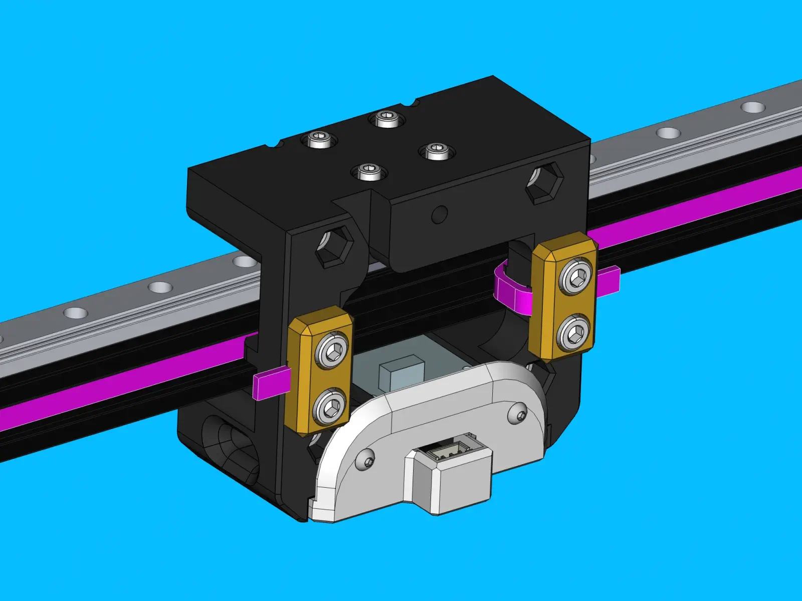
Step 24 of 37
Affix Belt Clamps
-
Use
belt-clampwith 2xM5x10-boltto clamp the left-side of theGT2-beltto thex-gantry-back -
Tighten each
M5x10-boltto 0.5 N.M
Step 25 of 37
Attach other side of belt
-
Pull the right-side
GT2-belttightly towardsx-motor-mountto tension it. -
Use
belt-clampwith 2xM5x10-boltto clamp the right-sideGT2-beltto they-gantry -
Tighten each
M5x10-boltto 0.5 N.M
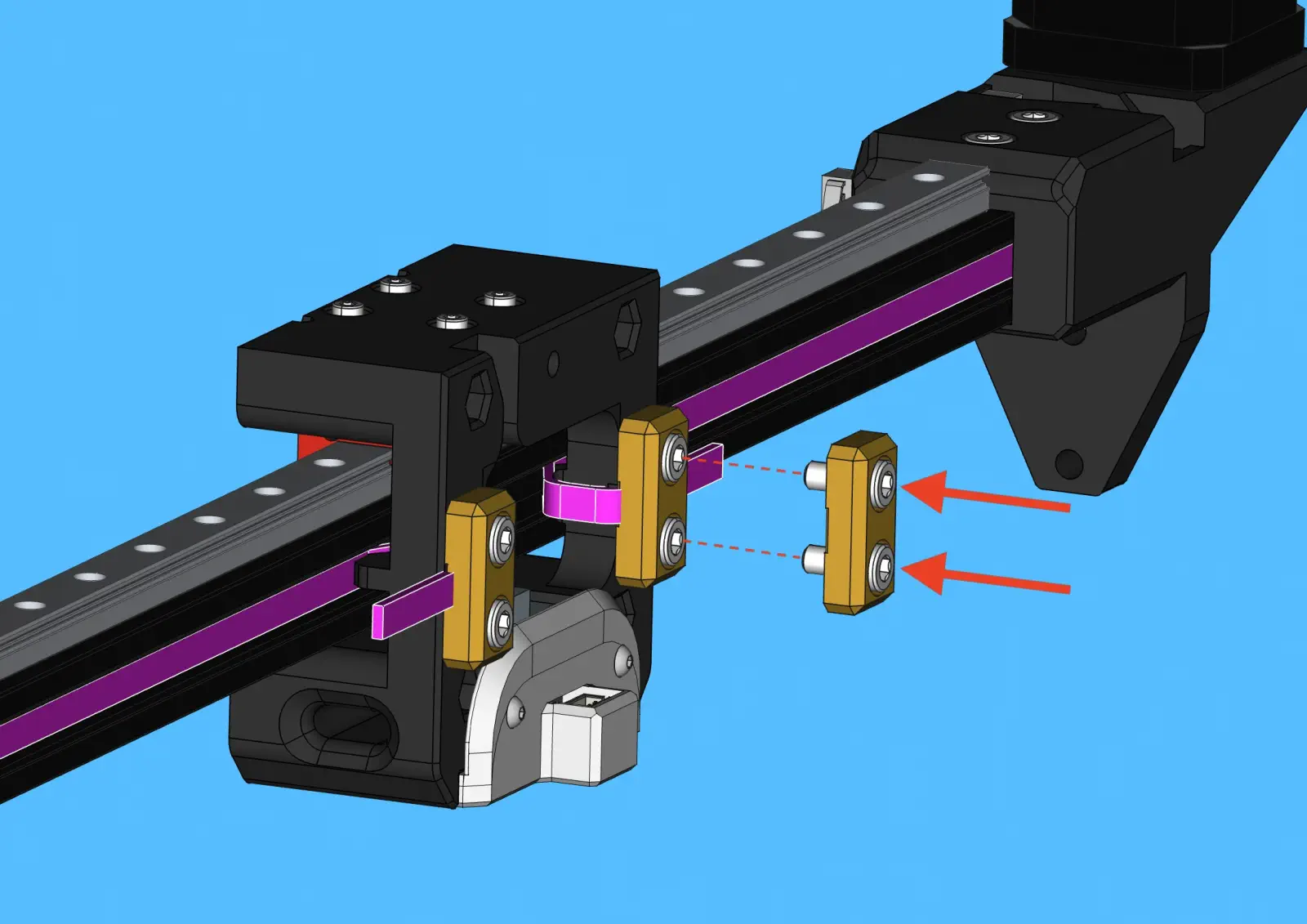
Step 26 of 37
Tension Belt
-
Rotate the
M3x16-boltclockwise onbelt-tensioner-arminstalled onx-idler-mountto tension theGT2-belt -
This will cause the
belt-tensioner-armto pull theidler-pulleyaway fromx-idler-mountadding desired tension to theGT2-belt
Step 27 of 37
Trim excess belt
-
For the
x-motor-mountside of thex-gantry-backprint, trim looseGT2-beltuntil flush againstbelt-clamp -
For the
x-idler-mountside of thex-gantry-backprint, trim looseGT2-beltuntil approx. 15mm ofGT2-beltremains pastbelt-clamp
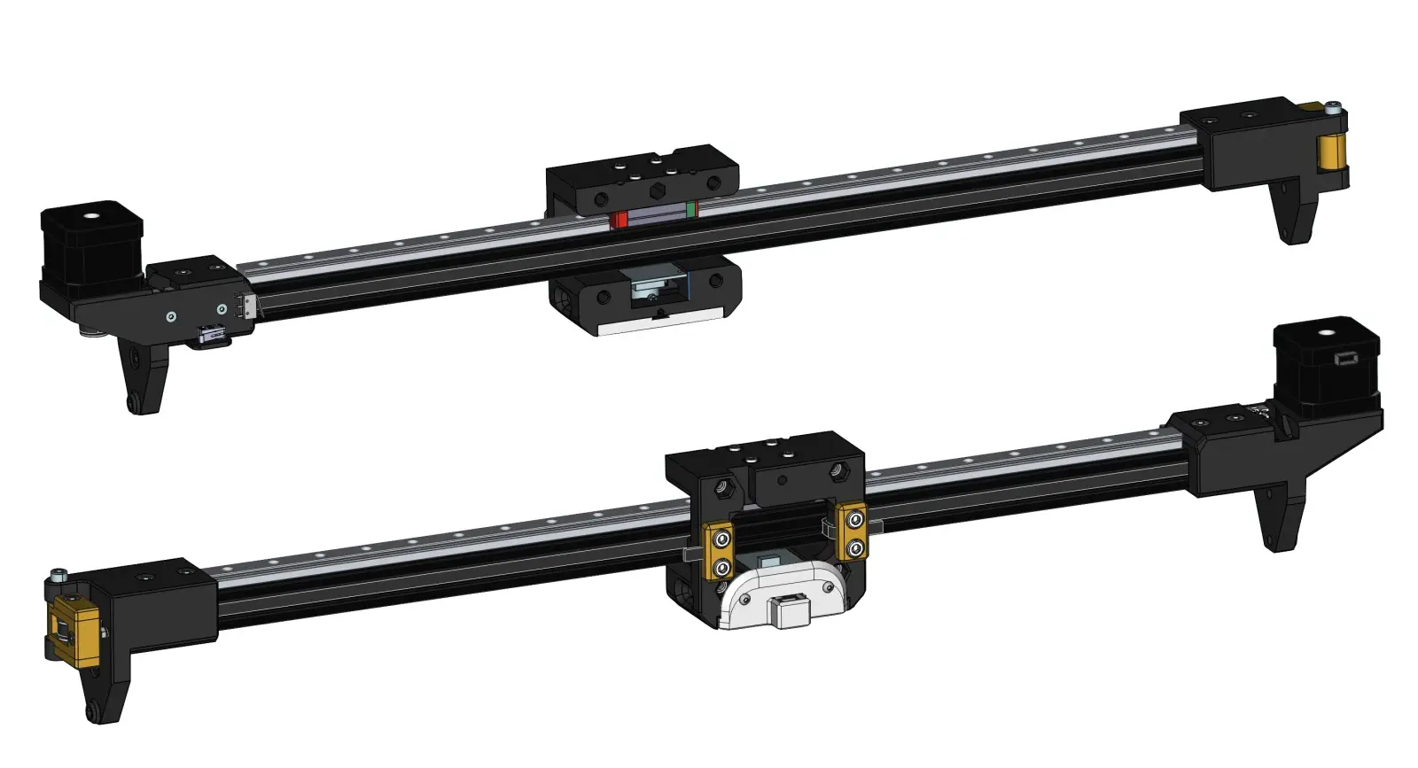
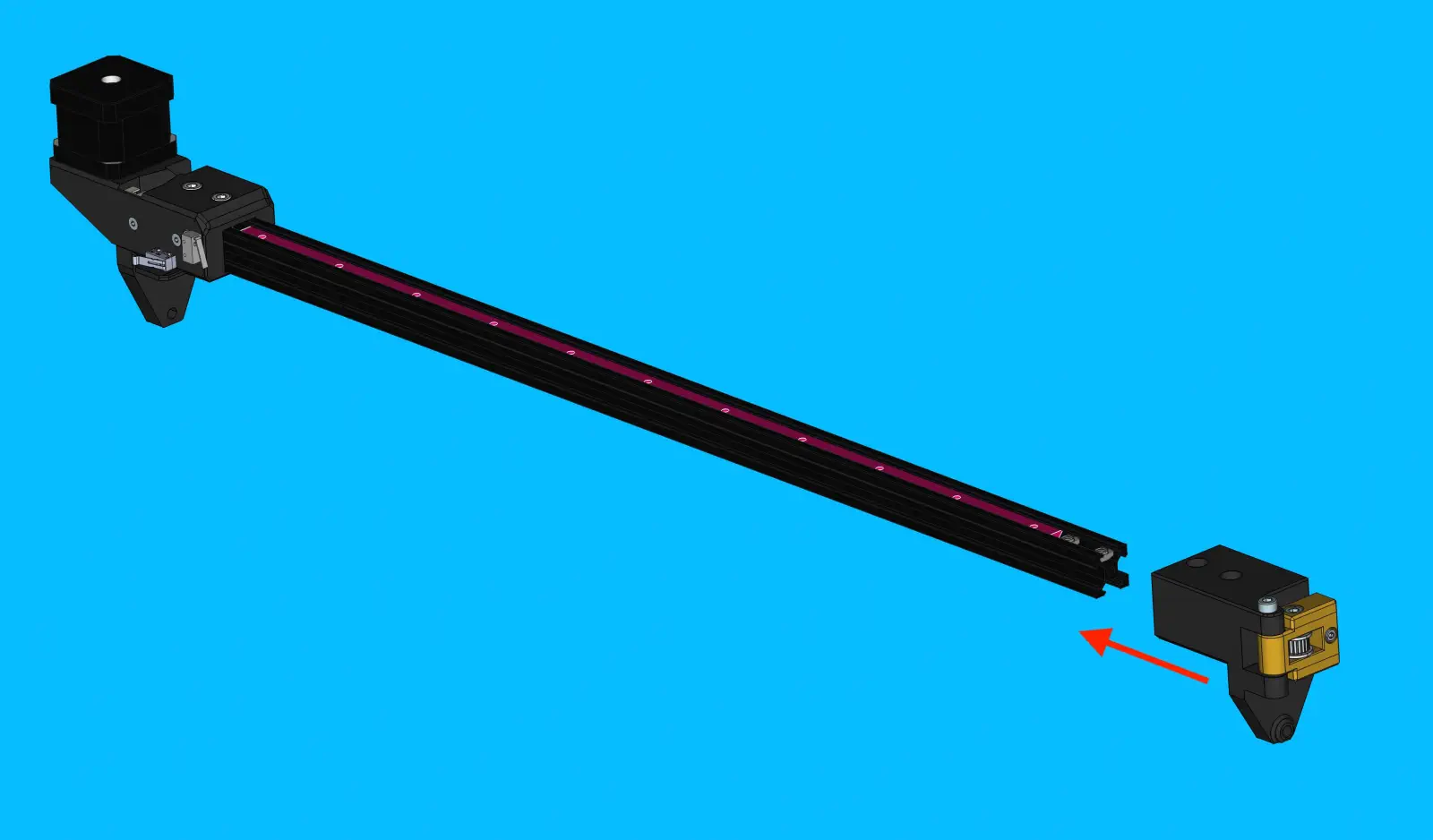
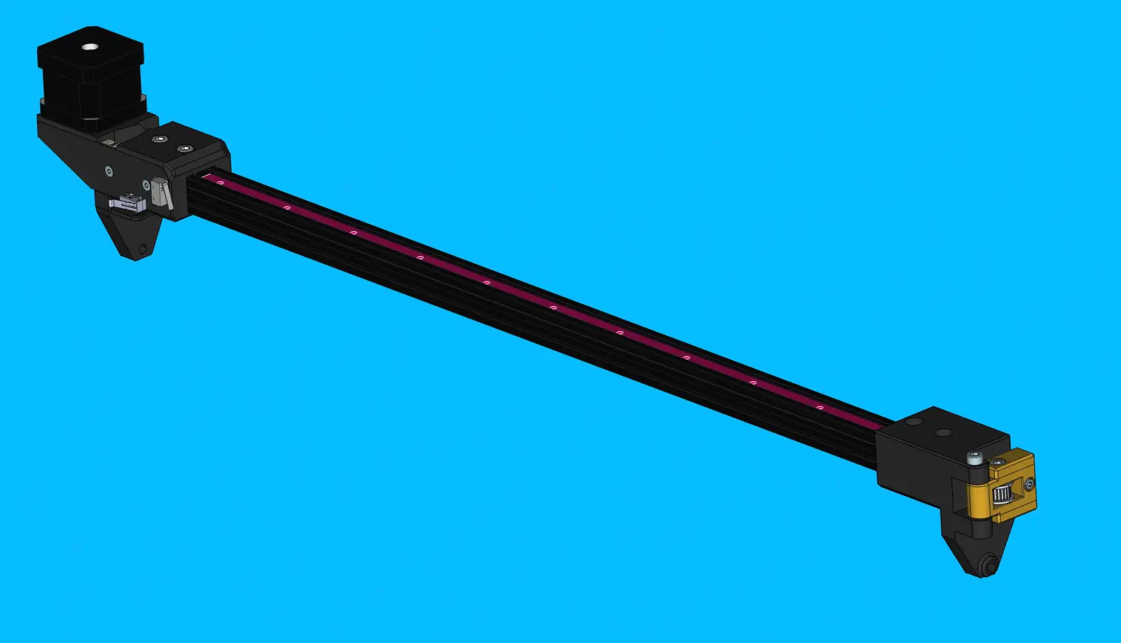
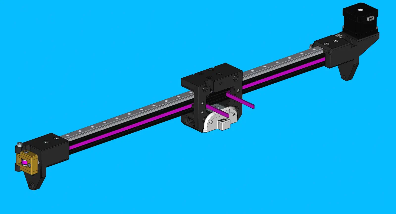
Step 28 of 37
Confirm progress
-
Check that finished
x-linear-axismatches the image before proceeding
Step 29 of 37
Prepare NEMA-17-stepper-motor for z-axis
-
Set
timing-pulleyheight onNEMA-17-stepper-motorshaft with jig -
The 1st set-screw tightened must contact the flat region of the motor’s shaft
Note
Tighten both set screws to 0.4 N/M
Step 30 of 37
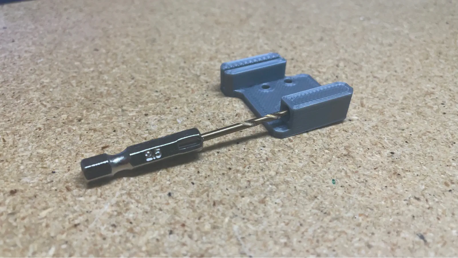
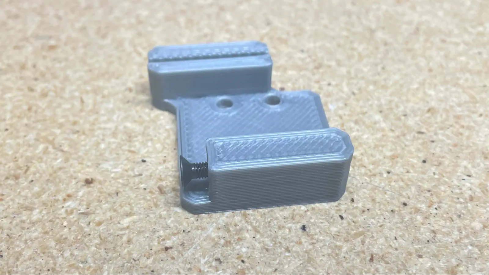
Prepare z-belt-subassembly
-
Prepare
z-gantry-backplate-right-
Drill out the limit switch striker bolt hole on
z-gantry-backplate-rightwith a 2.5mm drill bit -
Install 1x
M3x16-flathead-boltintoz-gantry-backplate-rightto a depth that roughly matches the image shown below- This screw depth will be precisely adjusted in later steps
-
-
Install both
z-gantry-backplate-leftandz-gantry-backplate-rightontogt2-belt-loop- Place a
gt2-belt-looponto thez-belt-alignment-jig - Place
z-gantry-backplate-leftandz-gantry-backplate-rightonto thez-belt-alignment-jigto align them correctly on thegt2-belt-loop - Twist
z-gantry-backplate-leftupwards to pull the completedz-belt-subassemblyoff of thez-belt-alignment-jig - Use a dull knife or other tool to push the
gt2-belt-loopall the way down into the cavity of eachz-gantry-backplate-####
TO DO: Add info about LOCTITE 435 Usage
- Place a
Step 31 of 37
Install M5-lock-nut into x-gantry-front
-
Use an arbor press to install an
M5-lock-nutinto backside ofx-gantry-front
Step 32 of 37
Install 2x linear rail onto x-gantry-front
-
Install 2x
linear-railby aligning them against the bumps found onx-gantry-front- Uses 3x
M3x12-self-tapping-button-headperlinear-rail - Tighten each bolt in place with the electic torque driver
- Uses 3x
Step 33 of 37
Install z-axis-limit-switch
- Secure with 2x
M3x12-self-tapping-button-head- Tighten each screw in place with the electic torque driver
-
Make sure each limit switch clicks and feels normal when actuated
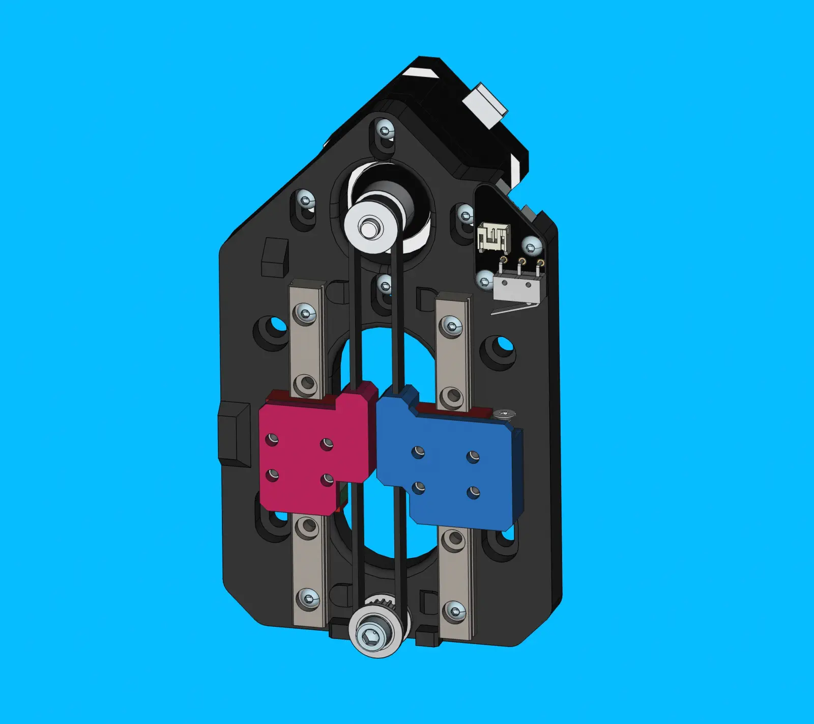
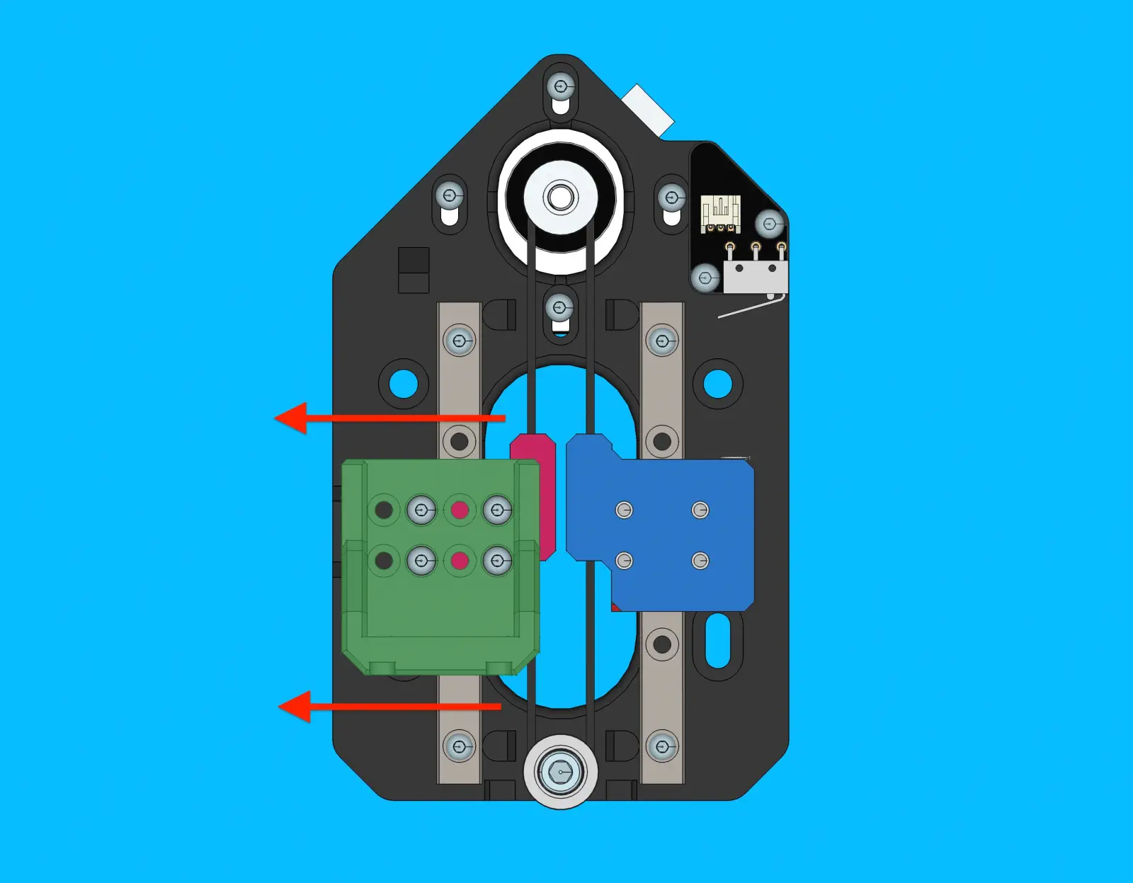
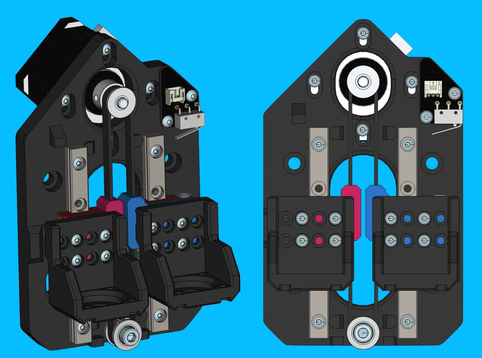
Step 34 of 37
Install z-axis belt drive components
- Secure
idler-pulleyontox-gantry-frontwith 1xM5x25-bolt, tightened enough that the pulley can rotate freely without resistance -
Check that the pulley can only rotate - it should not be able to move up and down if the bolt is tightened correctly
-
Begin by placing
z-belt-subassemblyontox-gantry-front-
The
z-gantry-backplate-rightshould fit over the rightlinear-rail-carriage, and the same goes for the left-side -
The
gt2-belt-loopshould wrap around theidler-pulley
-
-
Install the
NEMA-17-stepper-motorby angling it into thez-belt-subassembly- The limit switch connector will be at a 45º from the motor’s connector when everything is in the proper position.
-
Bolt
NEMA-17-stepper-motorontox-gantry-frontwith 4xM3x8-bolt- Leave the bolts loose for now
-
Tension
gt2-belt-loopby pulling the motor upwards before tightening the mounting bolts to 0.5 N/M- The belts should feel much firmer now - to test manually move the z-axis back and forth while inspecting the belts for sag when changing directions
-
You should be able to pluck the belt like a bass string
-
The
x-gantry-frontshould now match the image shown below:
Step 35 of 37
Install 2x z-gantry
-
Loosely attach a
z-gantryonto the left-sidelinear-rail-carriagewith 4xM3x8-boltper side -
Align
z-gantryparallel tolinear-railby lightly pressing it outward, while tightening the mounting bolts- Tighten bolts to 0.5 N/M, moving in a star pattern
-
Repeat this process to attach the second
z-gantryto the right-sidelinear-rail-carriage
Step 36 of 37
Install NEMA11-hollow-shaft-stepper
-
Bolt
NEMA11-hollow-shaft-stepperonto left-sidez-ganty- Attach with 4x M2.5x8 bolts
- Torque each bolt to 0.3 N/M
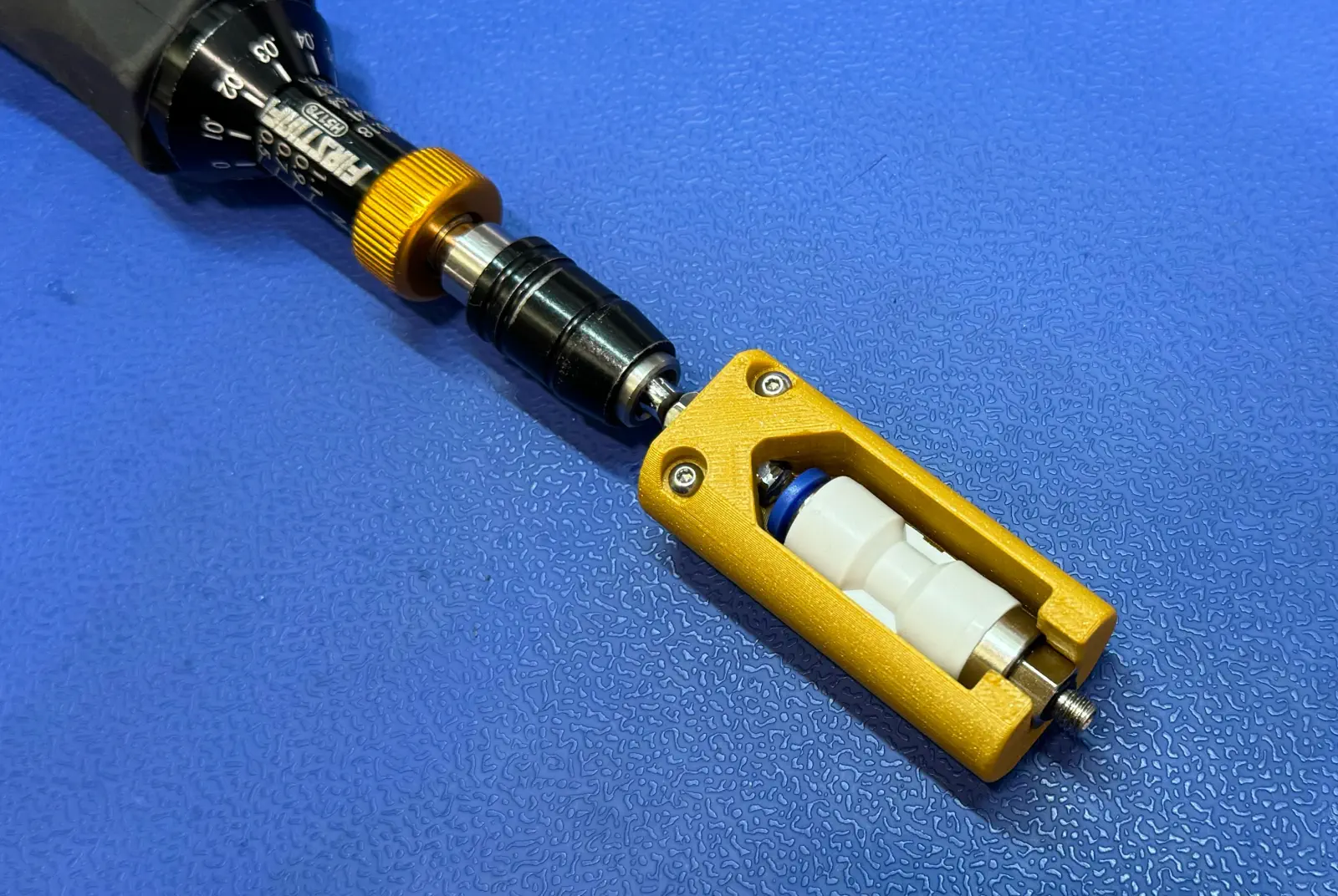
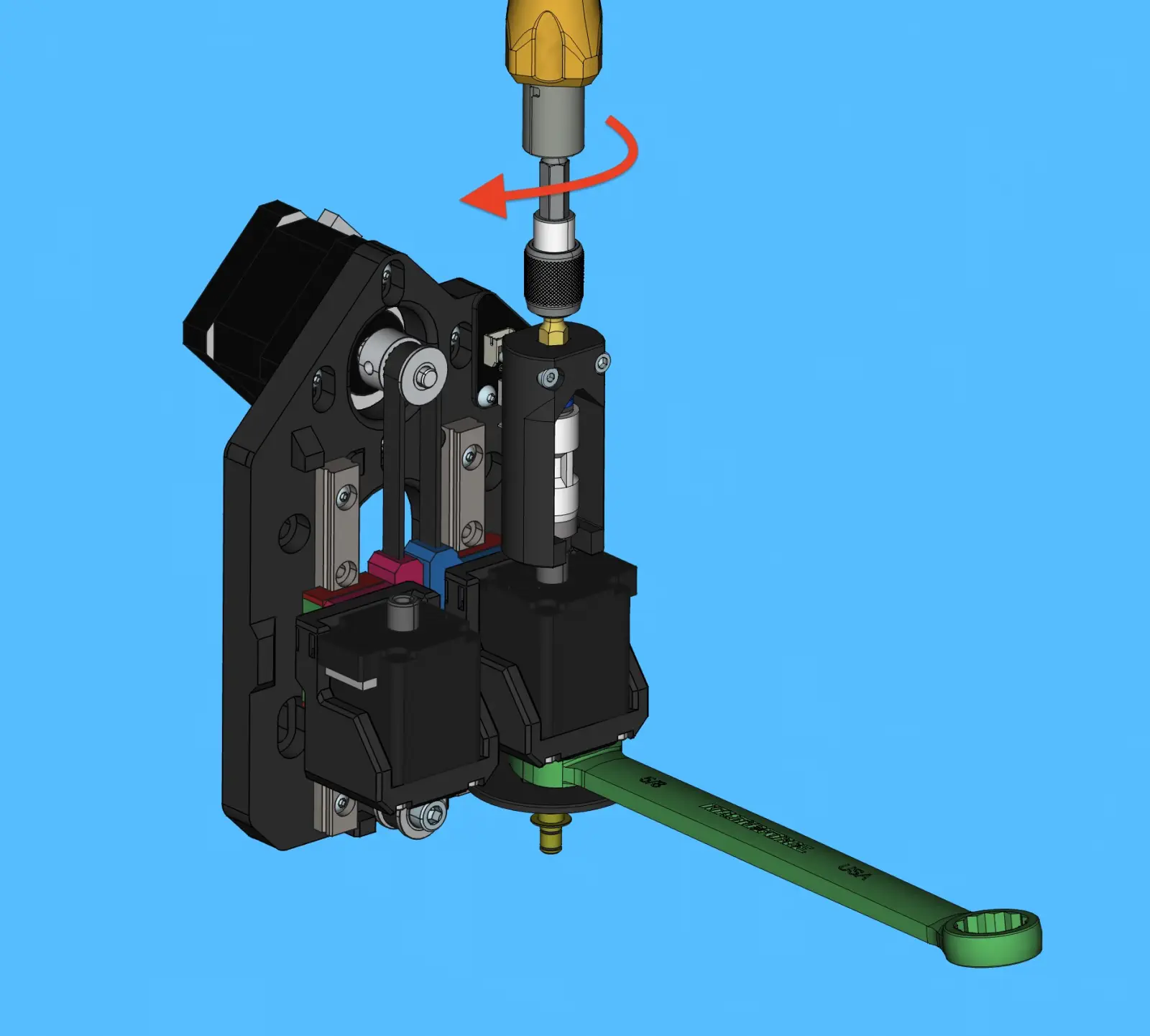
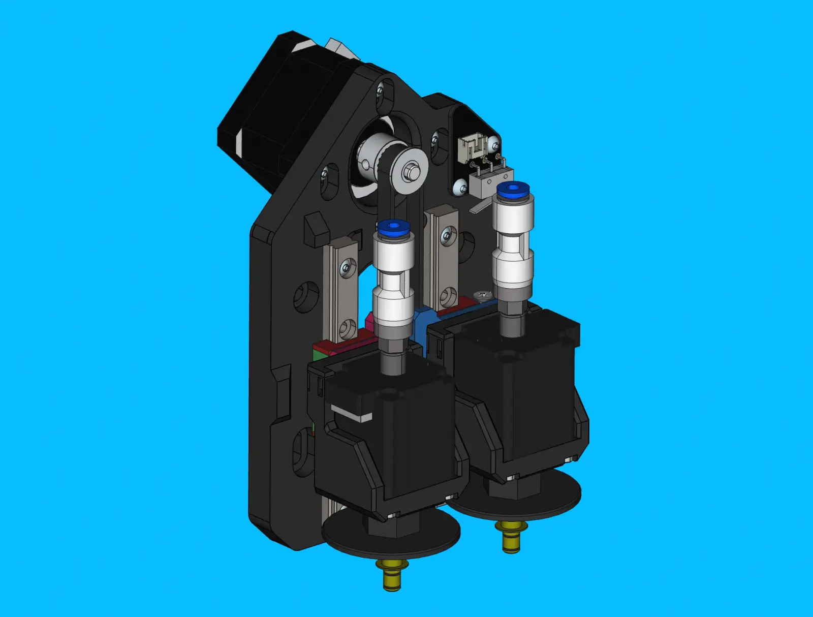
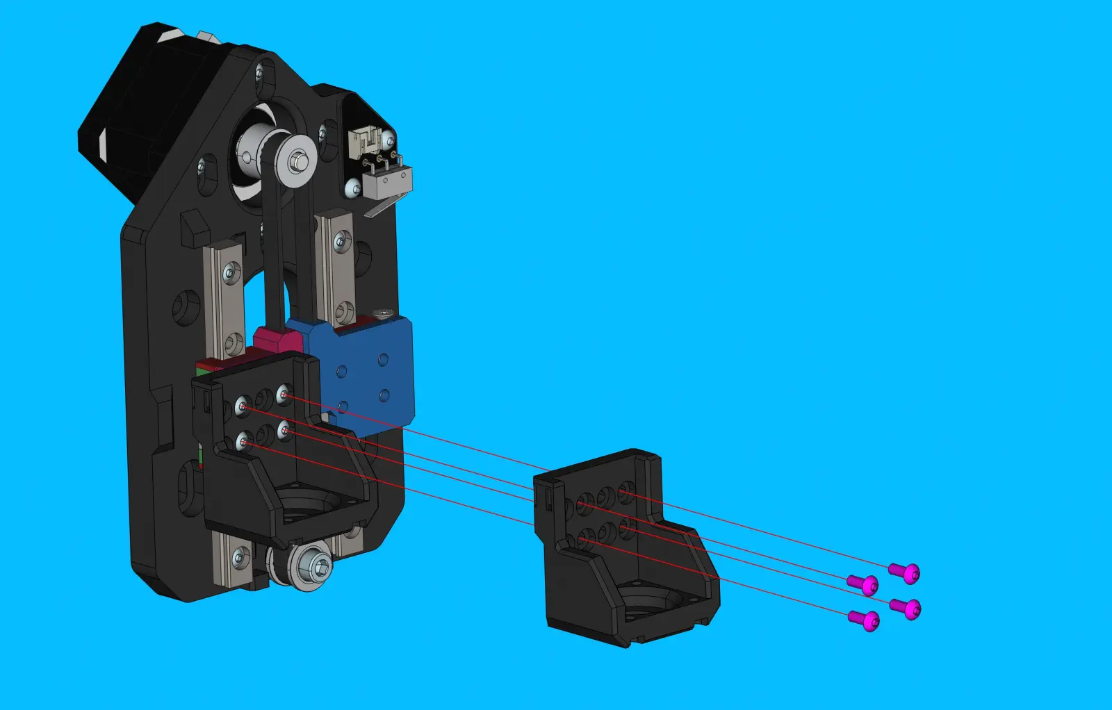
Step 37 of 37
Install toolhead components
-
Slide
nozzle-maskontonozzle-holderas shown in the image below -
Place
rotary-pneumatic-adapterintorotary-pneumatic-adapter-socket- Attach the custom socket to a torque driver if you have not already done so
- Set the torque driver to
0.5 N/Mfor the following steps
-
Install
nozzle-holderandrotary-pneumatic-adapterontoNEMA11-hollow-shaft-stepper- Begin by loosely threading
nozzle-holder w/attached nozzle-maskonto theNEMA11-hollow-shaft-stepper(on the side closest to theidler-pulley) - Install
rotary-pneumatic-adapterontoNEMA11-hollow-shaft-stepper(on the side closest to the motor's cable connector) - Place a 16mm wrench onto the flats found on
nozzle-mask - Tighten the toolhead components onto the
NEMA11-hollow-shaft-stepperby torquing therotary-pneumatic-adapter
- Begin by loosely threading
-
Repeat above process to attach a
rotary-pneumatic-toolhead-assemblyto the left-sidez-gantry