Staging Plate
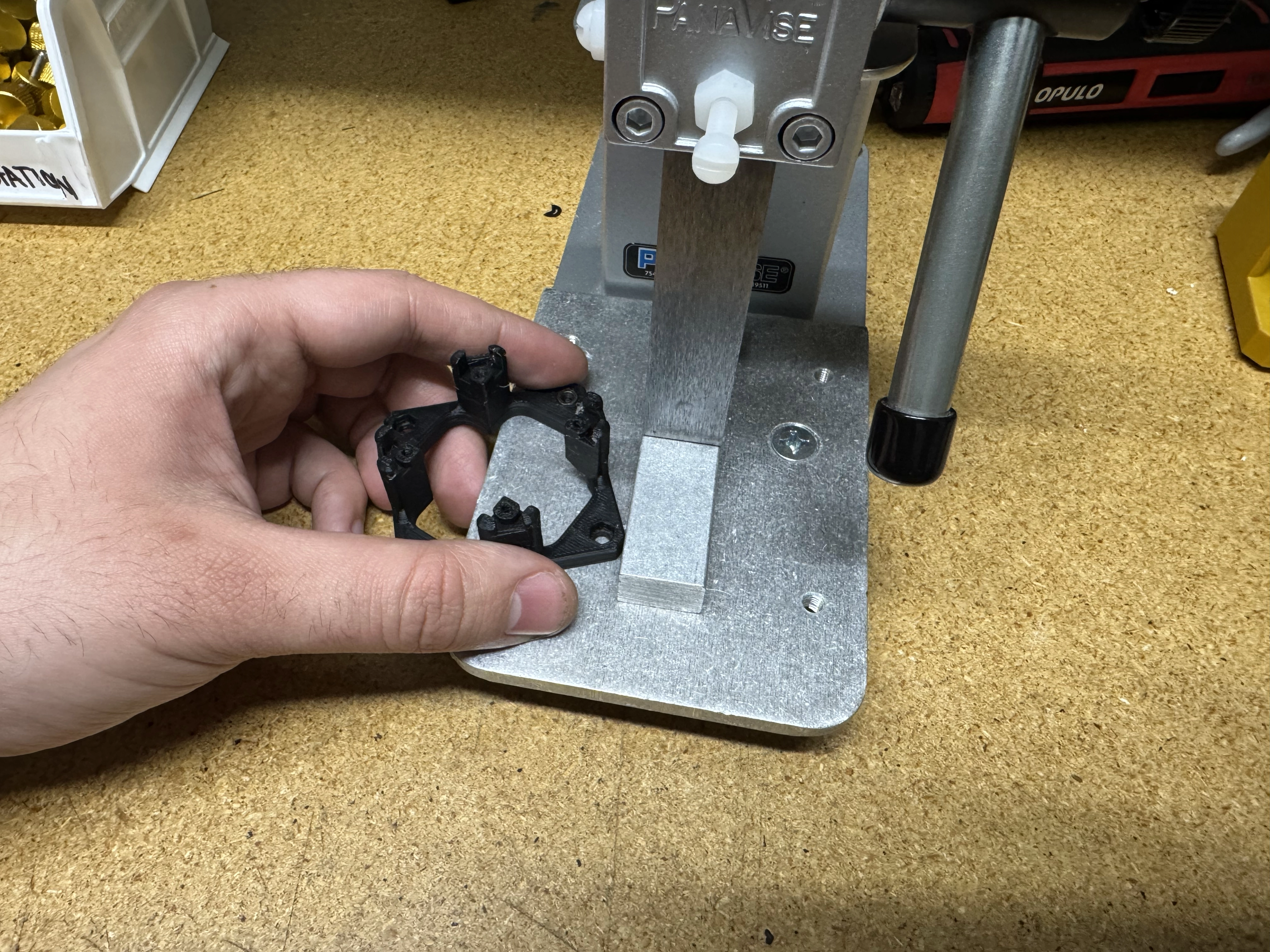
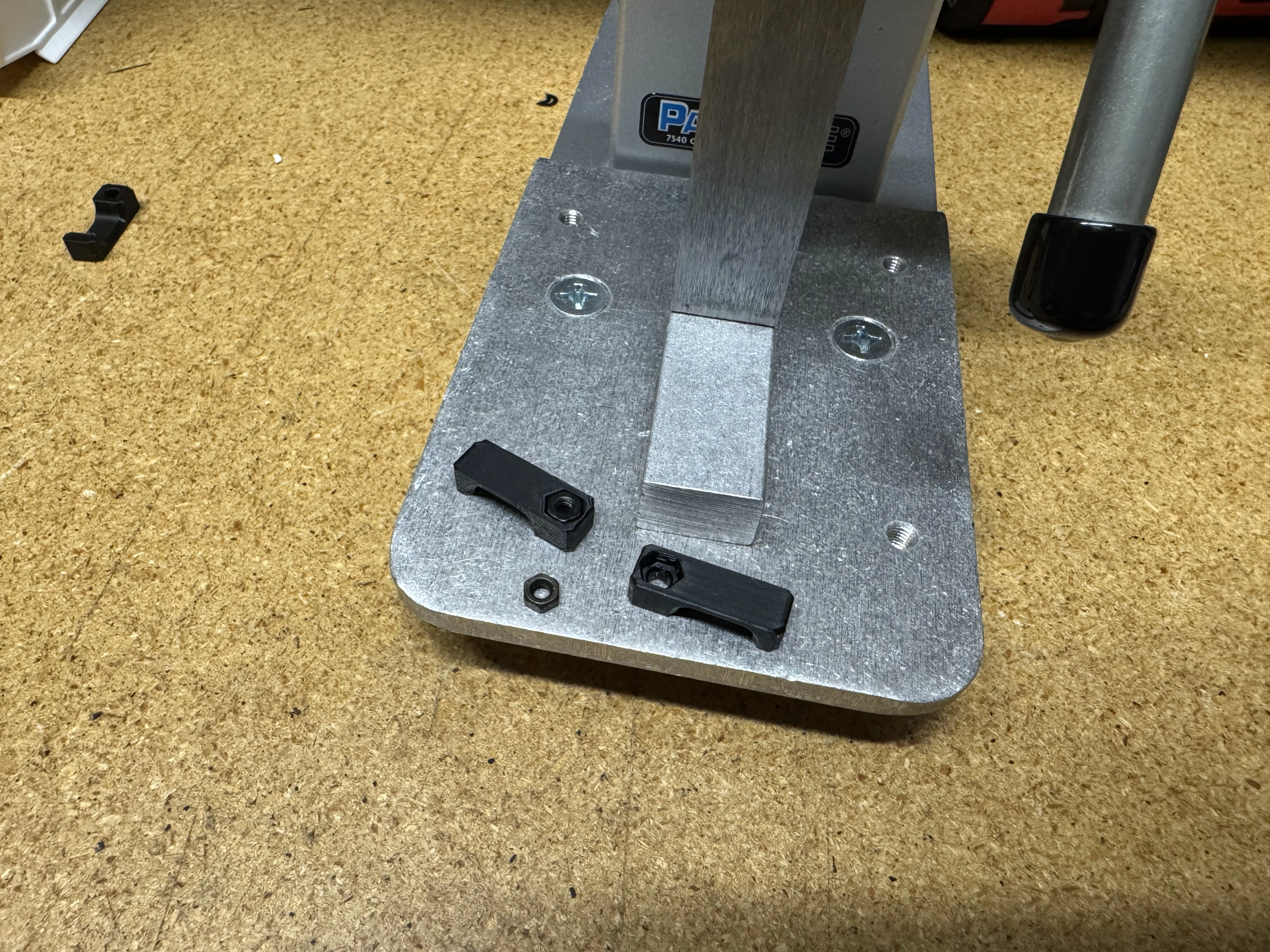
Install hardware into 3D printed components
- Use an arbor press to insert the given quantities of
M3-hex-nutinto the following parts: - 4x for
bottom-camera-mount -
3x for 3x
peek-cable-clampNote
Be sure to change the arbor press tip for the different prints as needed.
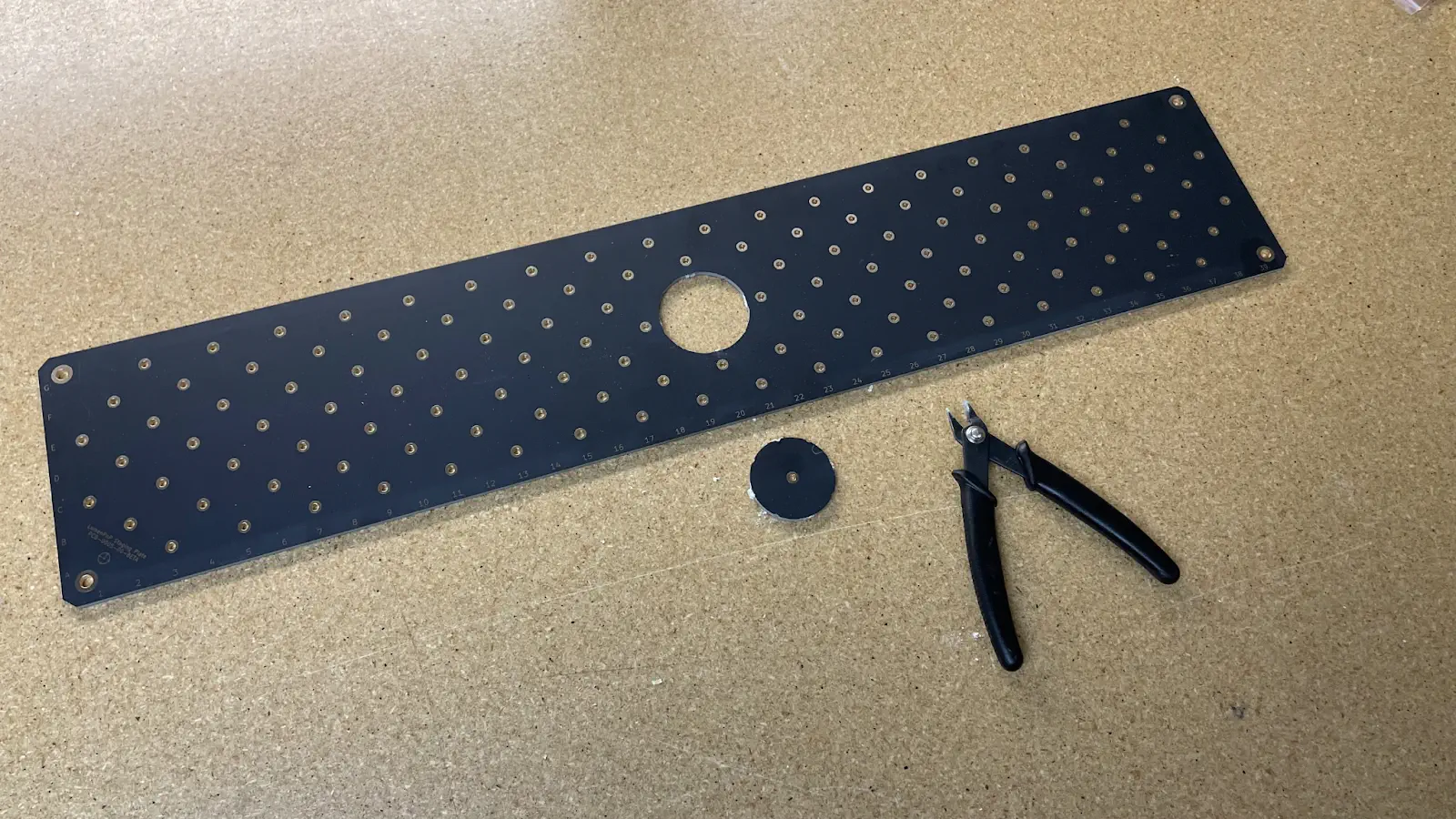
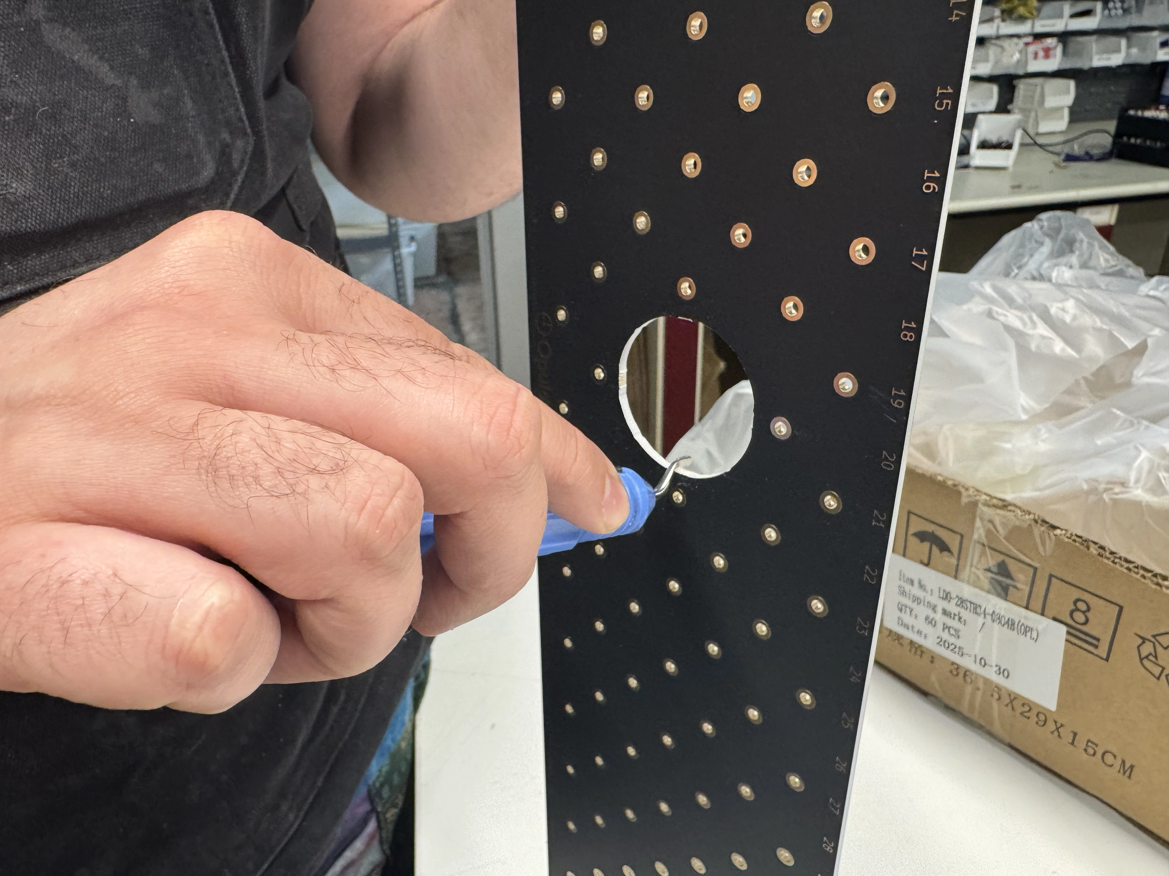
Removing punch-out from PCB-0003
-
Remove the punch-out from center of
PCB-0003with flush cutters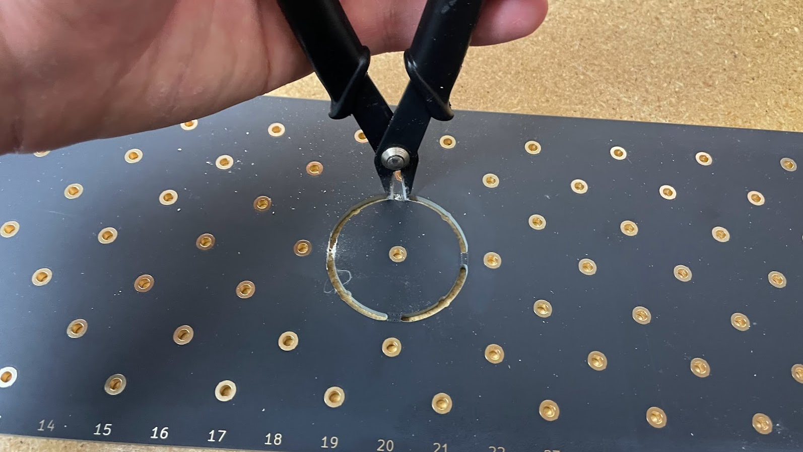
-
Clean up hole with a deburring tool after punch-out has been removed
-
Clean both sides of
PCB-0003with an IPA-soaked shop rag
Focus the bottom-camera
-
Thread the
bottom-camera-cablethroughbottom-camera-coverand connect it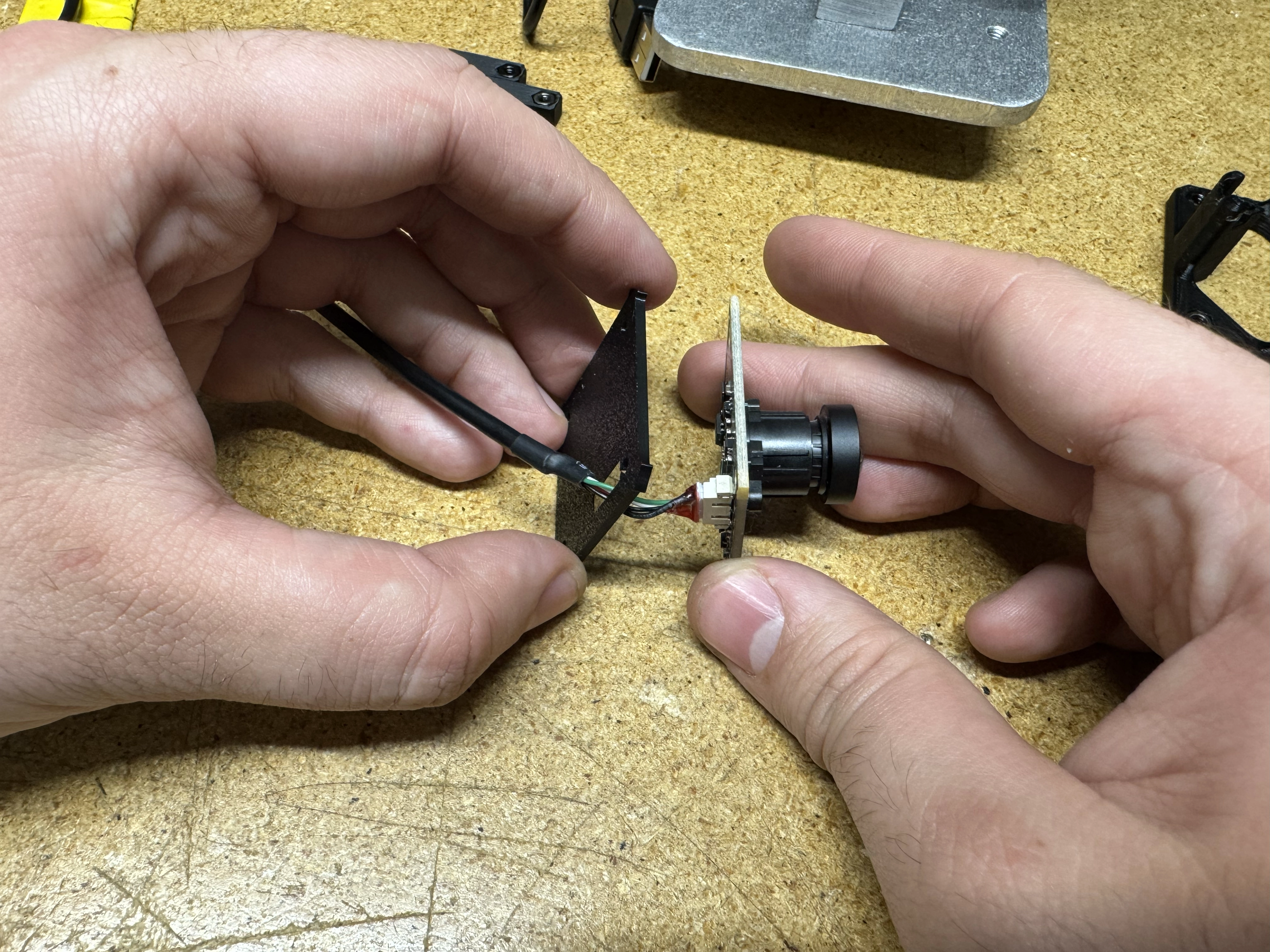
-
Remove the lens cap from
bottom-camera -
Use
bottom-camera-focus-jigto pre-focusbottom-camera -
Turn on the light for the jig and attach
bottom-camera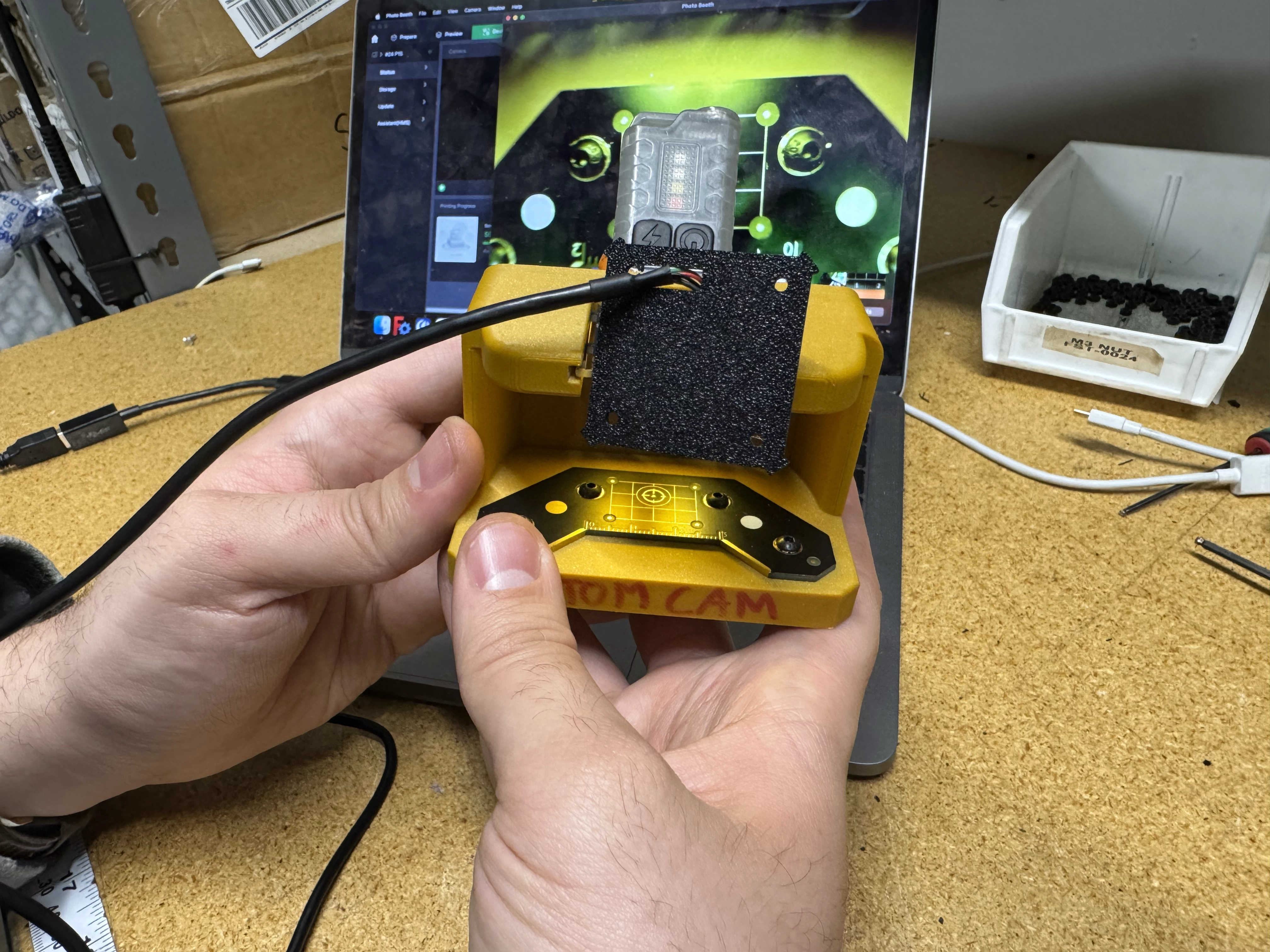
-
Connect the USB cable on
bottom-camera-focus-jigto a computer and open its native camera viewing application - Use Photobooth if on Mac OSX or Cheese if on Linux
- Confirm that the camera feed is running in 720p, sometimes it can launch in 360p or 480p
- Within the camera viewing application, change the selected camera to
PnP Bottomto view the camera feed of the bottom-camera
If the listed camera is something other than PnP Bottom, the device may either be incorrectly programmed or mixed up with a top-camera
Please take this as an opportunity to double-check the device name even if the computer switched to the correct camera feed automatically.
-
Rotate the camera lens until the live viewport shows the datum board as focused as possible
Creating bottom-camera-assembly
-
Attach
bottom-cameraandbottom-camera-covertobottom-camera-mountwith 4xM2.5x8-bolt
-
Confirm
bottom-camera's JST connector is in the correct orientation as indicated below:
-
Clean
bottom-light-mountprint by removing any loose stringy plastic with a heat gun and/or razer blade (as needed) -
Install
bottom-ring-lightintobottom-light-mount
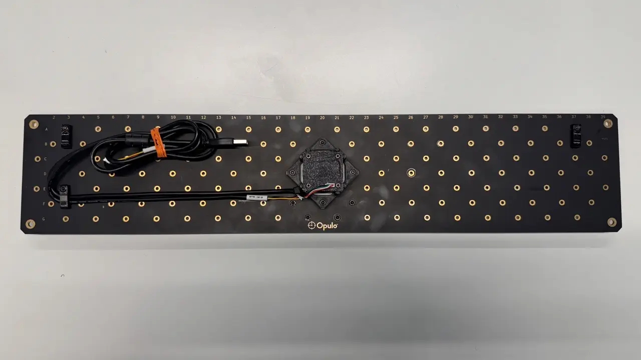
Final Assembly
Installing bottom-camera-assembly
It is recommended to wear gloves when handling the staging-plate.
-
Attach
bottom-camera-assemblyontostaging-platewith 4xM3x16-bolt
-
The JST cable connector found on
bottom-ring-lightshould match the orientation shown below when installed - as close to the Opulo logo as possible and in line withstaging-platecolumn 18
-
The JST cable connector found on
bottom-camerashould match the orientation shown below when installed - as close to the Opulo logo as possible
-
Plug
bottom-light-harnessintobottom-ring-light -
Plug
bottom-camera-harnessintobottom-camerabefore securing cable tobottom-camera-mountwith azip-tie
Install datum-board and datum-board-mount
- Use four
M3x16mm-boltand 4xM3-hex-nutto secure thedatum-boardanddatum-board-mounttostaging-plateon the rear of thebottom-camera, through holes: B18, A19, A21, B22.
- Use a 2.5mm hex wrench and a 5.5mm (6mm if 5.5mm is unavailable) socket wrench to tighten these bolts
-
The fisheye calibration pattern should be facing down, and the gold grid lines and fiducial in the center of the Opulo logo facing upwards
Install secondary fiducial
-
Use two
M3x10-hex-headto attachsecondary-fiducial-brackettostaging-plate. Make sure the closed portion of the. bracket is facing thering-light.
-
Fasten
secondary-fiducial-brackettostaging-platewith twom3-hex-nut.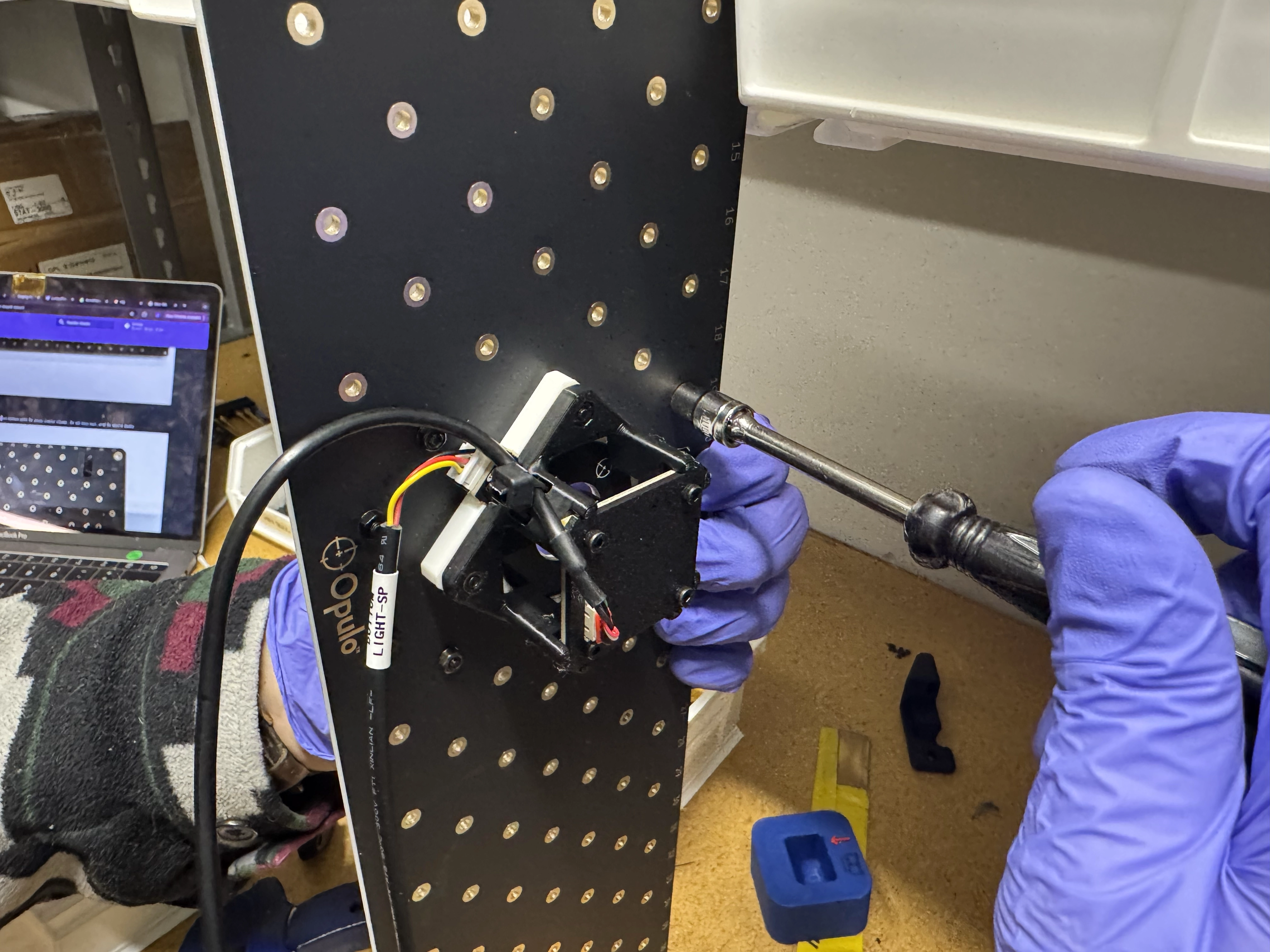
Performing cable management
-
Clamp cables in the locations shown below with 3x
peek-cable-clamp, 3xm3-hex-nut, and 3xm3x14bolts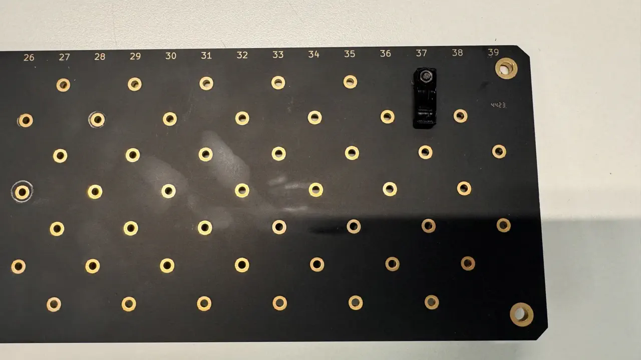
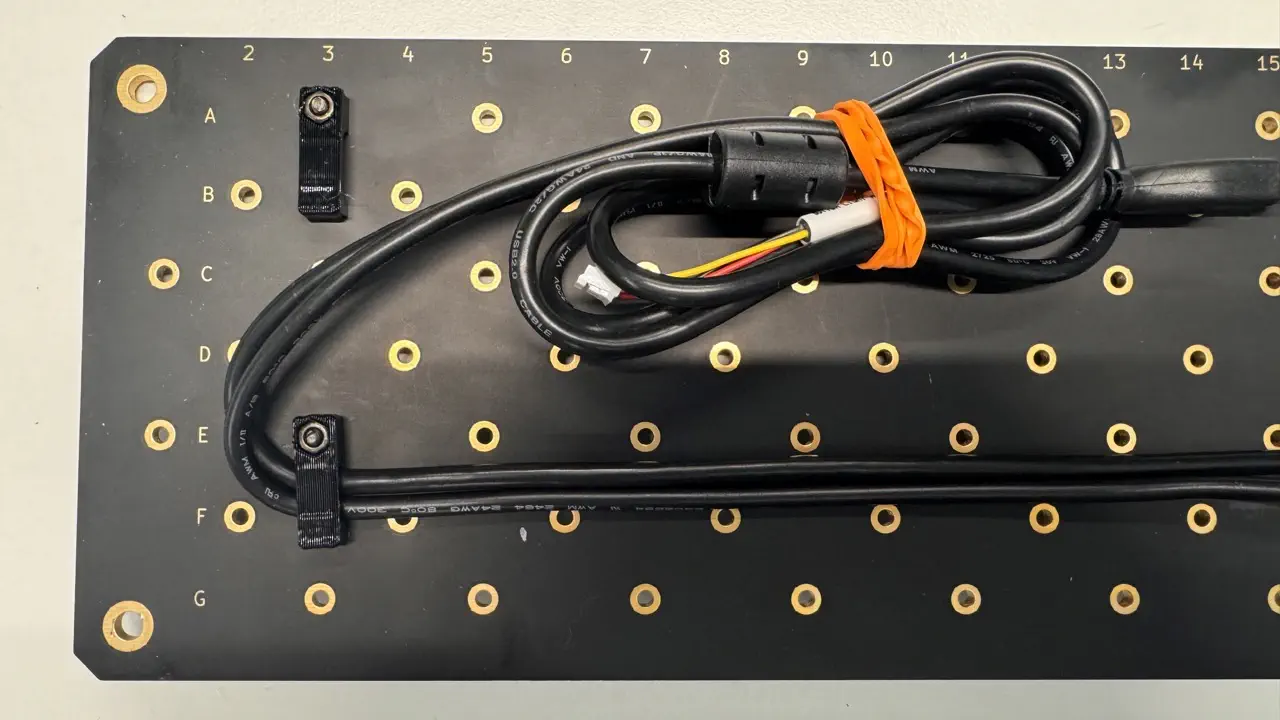
-
After securing the cables, tie them up with a
rubber-band