Packaging LumenPnP v4
Reviewing packaging layout
-
The following components are packaged into the
lower-foam-tray:y-gantry-lefty-gantry-rightx-gantrynozzle-rack-asmgetting-started-kittool-kit-bagfeeder-blade-harness-setx-cable-chain-support- 2x
front-leg-extension - 2x
back-leg-extension
-
The following components are packaged into the
upper-foam-tray:primary-staging-plateaux-staging-platestatic-camera-footaux-staging-plate-footbagged-10x-extrusion-cable-clipssquaring-brackety-limit-strikerdrag-chain-assemblyfront-feeder-railrear-feeder-rail24v6A-power-supplypower-cable
Package lower-foam-tray
The following steps must be conducted by someone other than the original assembler.
tool-kit-bag and back-leg-extension
-
Confirm
lumenpnp-v4-hardware-kitis present intool-kit-bagIf OK continue onward
-
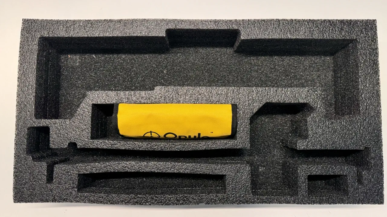
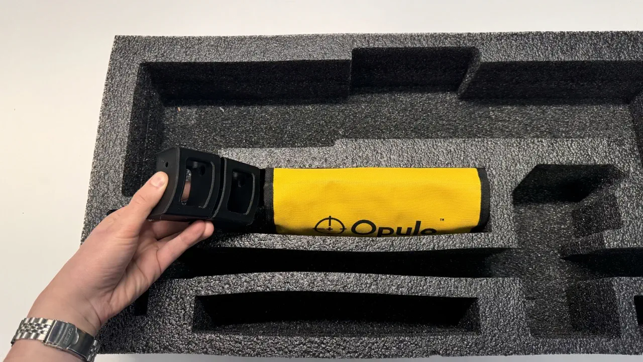
Add
tool-kit-baginto the middle region oflower-foam-tray- Orient the
tool-kit-bagso its Opulo logo faces thex-gantry-toolhead
- Orient the
-
Insert 2x
back-leg-extension- stacking them on the left oftool-kit-bag- Confirm both pieces have
rubber-feetinstalled
- Confirm both pieces have
getting-started-kit and feeder-blade-harness-set
-
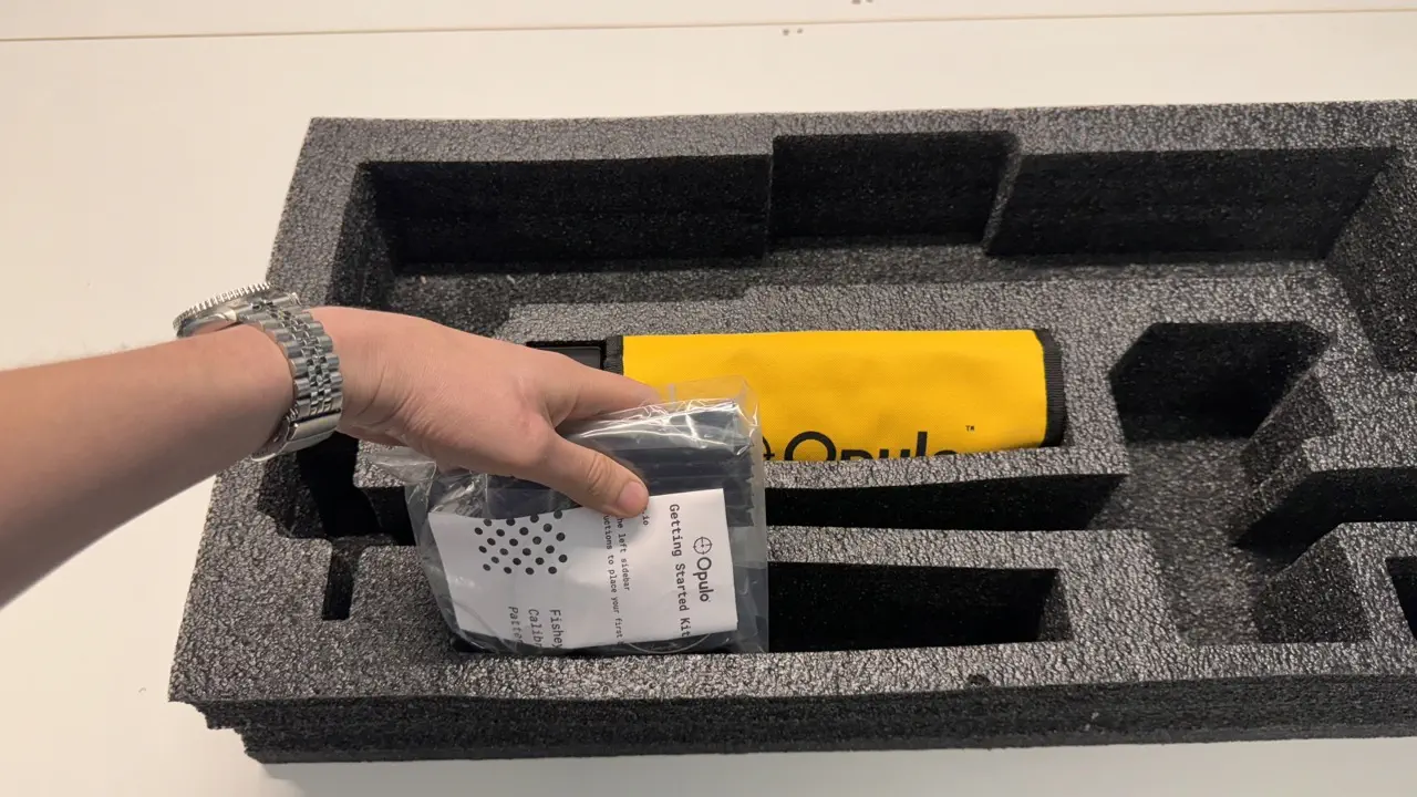
Insert
getting-started-kitinto the lower left region of tray- QC must be performed if collecting
getting-started-kitpieces from anything other than a green QC-Pass bin - QC this item by weighing and confirming a mass of either 168g or 150g (varies based on the version of tape used)
- QC must be performed if collecting
-
QC the
feeder-blade-harness-set. All four connectors must have the same wire color order as each other.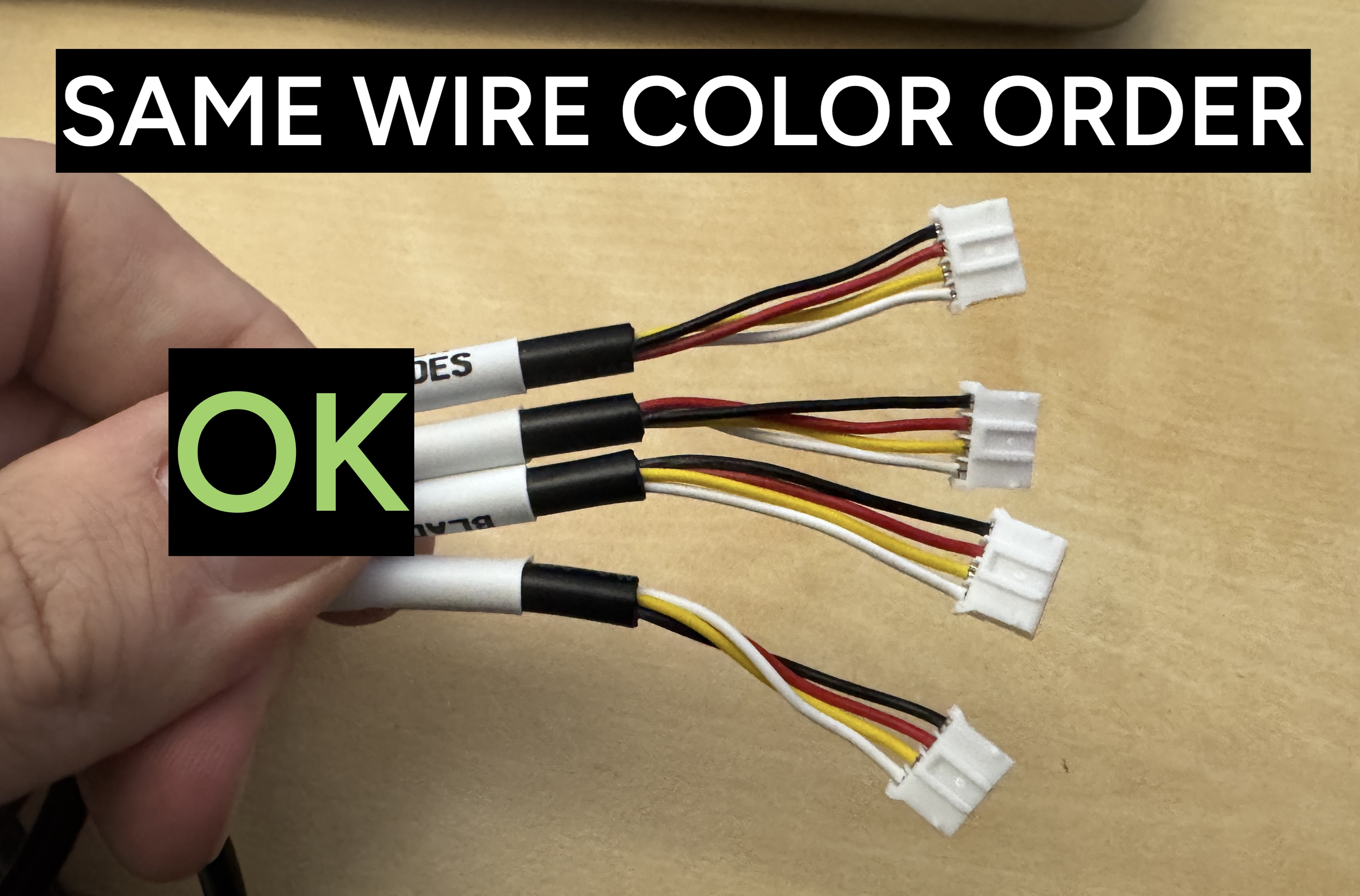
-
Insert
feeder-blade-harness-setto the right ofgetting-started-kit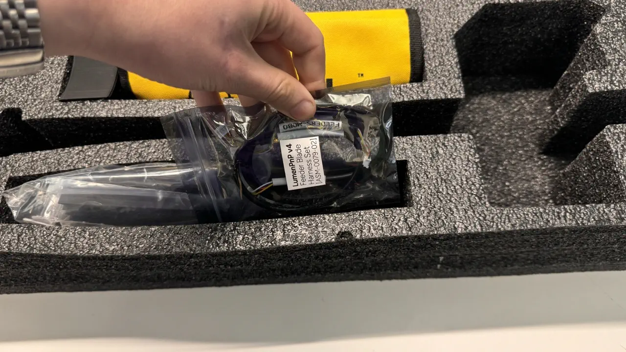
x-gantry
-
Perform
x-gantryQCGT2-belthas been trimmed to appropriate length:- Flush on
x-motor-mountside - Approx. 15mm on
x-idler-mountside
- Flush on
lens-capis present ontop-camera- The wire connectors on both
NEMA-11-stepper-motorunits face away from each other - Confirm each
nozzle-holderfulfills the following requirements:- Tip of the nozzle around the O-Rings has visible lubrication
- Moves smoothly and in a straight path when actuated manually
- Springs back to the extended position after being depressed by hand
z-belt-loopfeels appropriately tensioned when plucked- Each
z-gantrymoves smoothly when actuated back-and-forth by hand - 1x
M5-hex-nutis installed inx-gantry-backfor mountingcable-splay - The wire connector on
NEMA-17-stepper-motorthat is attached tox-gantry-frontfacesz-limit-switch - The wire connector on
NEMA-17-stepper-motorthat is attached tox-motor-mountfaces away fromxy-limit-switch linear-railis centered atopalu-extrusionx-idler-mountandx-motor-mountare secured toalu-extrusionwith 2xM5x10-boltper sidebelt-tensioner-armis installed onx-idler-mountin the correct orientation (IE acorn-nut facing touches print)timing-pulleyfor both x & z are tightened down and at proper heightGT2-beltlays flat and is roughly centered inalu-extrusionchannelGT2-belthas been correctly tensioned (40 < Newtons to dislodge Acorn Nut< 60)x-gantry-toolheadmoves smoothly when actuated back and forth by handtop-ring-lightis present with the wire connector visiblex-gantry-frontis fully tightened on and cannot rotate when torqued- both
z-gantryprints are fully tightened on and cannot rotate when torqued
If all checks pass, continue onward
-
Package
x-gantryintolower-foam-tray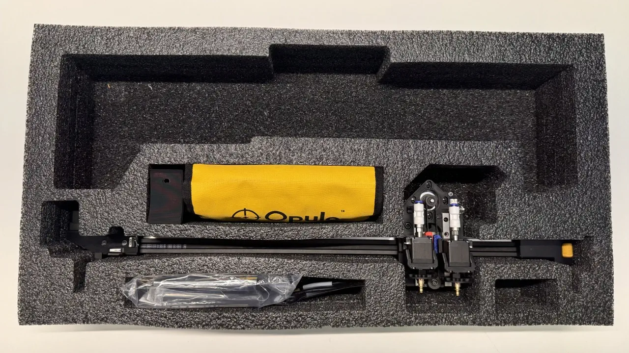
x-cable-chain-support
-
Place
x-cable-chain-supporton the bottom of they-gantrypocket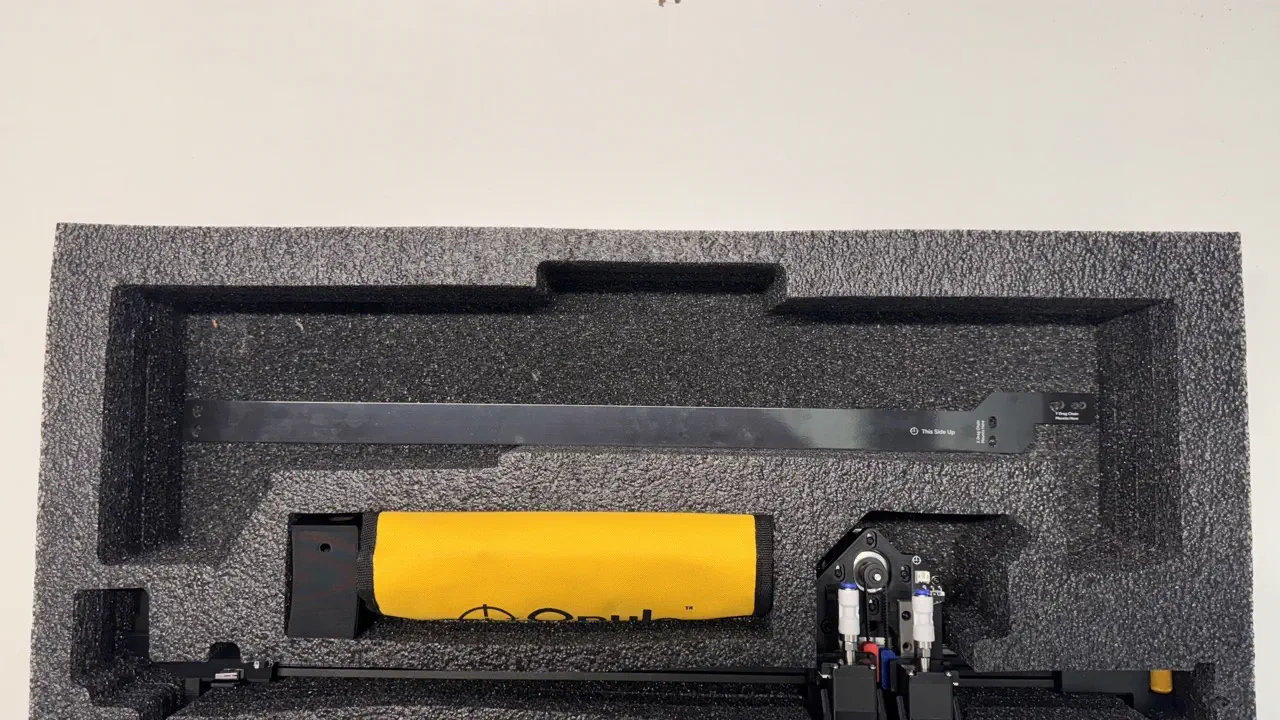
y-gantry-right
-
Perform
y-gantry-rightQC- Confirm M5 bolts are installed in every recessed region
M5-hex/square-nutinstalled where required:- 2x
M5-hex-nutpressed into bottom offront-right-leg - 1x
M5-hex-nutpressed into bottom ofback-leg - 2x
M5-hex-nutpressed intoy-gantryon textured face - 2x
M5-square-nutpressed intoy-gantryfor attachingx-cable-chain-support
- 2x
GT2-belthas been trimmed to appropriate length:- Flush on
front-right-legside - Approx. 15mm on
back-legside
- Flush on
GT2-belthas been correctly tensionedbelt-tensioner-armis installed onfront-right-legin the correct orientation (IE acorn-nut facing touches leg)linear-railis centered atopaluminum-extrusiony-gantrysits flat onlinear-rail-carriagey-gantryfeels smooth and free of friction across the y-min to y-max travel range when actuated by handGT2-beltlays flat in thealu-extrusionchannels- 3x
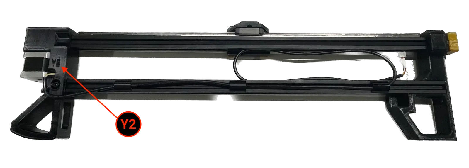
extrusion-cable-cliphave been installed onto the loweralu-extrusion timing-pulleyis tightened down and at proper heightY2cable is secured with a zip-tie and exits the port labeledY2
If all checks pass, continue onward
-
Package
y-gantry-rightintolower-foam-tray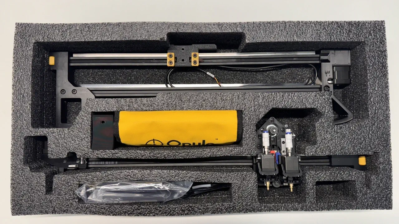
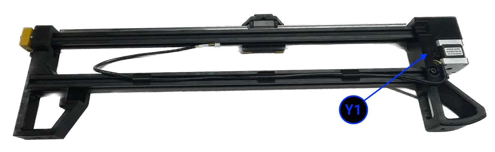
y-gantry-left
-
Perform
y-gantry-leftQC- Confirm M5 bolts are installed in every recessed region
M5-hex/square-nutinstalled where required:- 2x
M5-hex-nutpressed into bottom offront-left-leg - 1x
M5-square-nutpressed into side offront-left-legfor use withy-limit-striker - 1x
M5-hex-nutpressed into bottom ofback-leg - 2x
M5-hex-nutpressed intoy-gantryon textured face - 2x
M5-square-nutpressed intoy-gantryforx-cable-chain-supportmounting
- 2x
GT2-belthas been trimmed to appropriate length:- Flush on
front-left-legside - Approx. 15mm on
back-legside
- Flush on
GT2-belthas been correctly tensionedbelt-Tensioner-armis installed onfront-right-legin the correct orientation (IE acorn-nut facing touches leg)linear-railis centered atopaluminum-extrusiony-gantrysits flat onlinear-rail-carriagey-gantryfeels smooth and free of friction across the y-min to y-max travel range when actuated by handGT2-beltlays flat in thealu-extrusionchannels- 3x
extrusion-cable-cliphave been installed onto the loweralu-extrusion timing-pulleyis tightened down and at proper heightY1cable is secured with a zip-tie and exits the port labeledY1
If all checks pass, continue onward
-
Package
y-gantry-leftintolower-foam-tray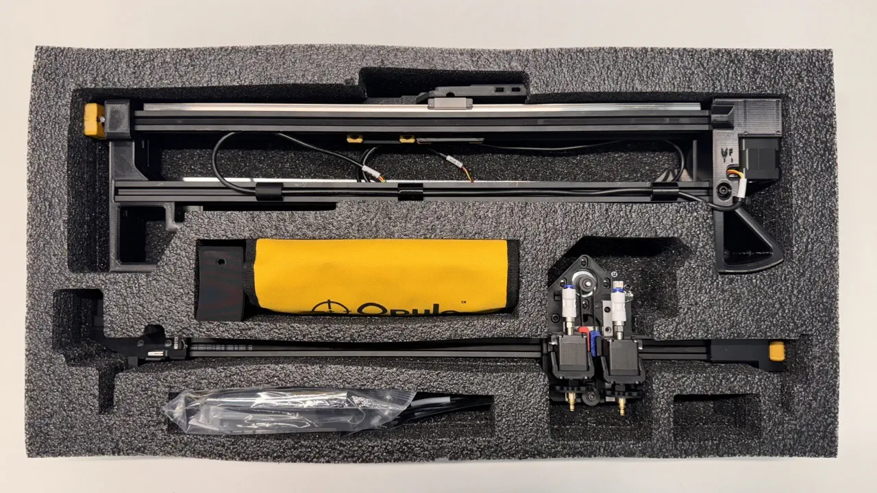
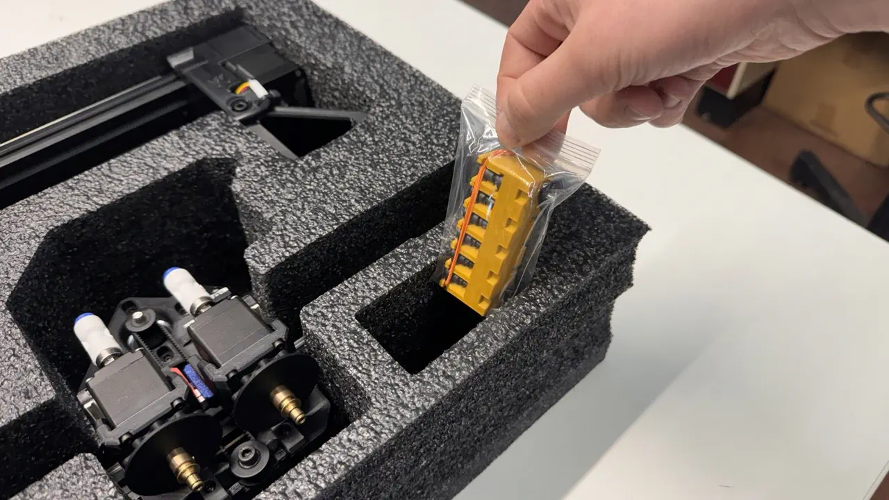
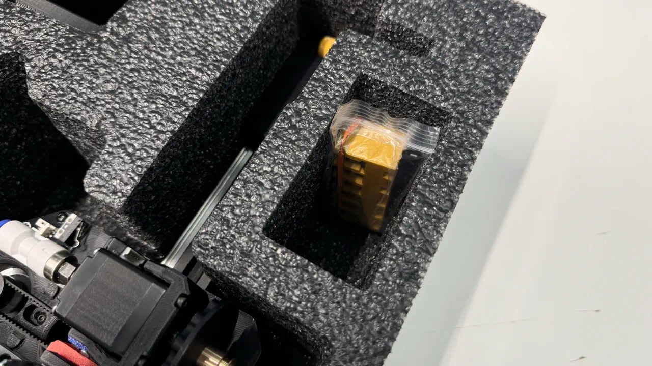
front-leg-extension and nozzle-rack-asm
-
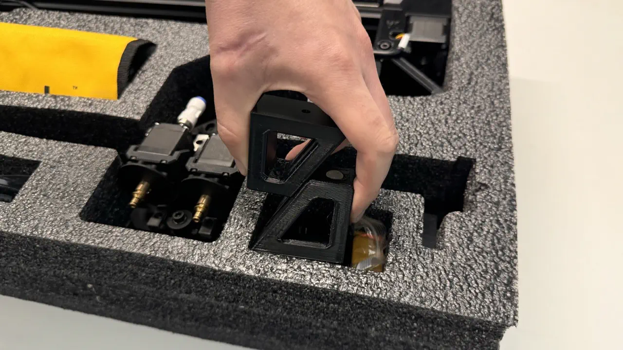
Insert
nozzle-rack-asminto the bottom right pocket- Confirm
nozzle-rackhas all its mounting hardware installed by peering through the bag
- Confirm
-
Insert 2x
front-leg-extension, stacking them in the same region- Confirm both pieces have
rubber-feetinstalled
- Confirm both pieces have
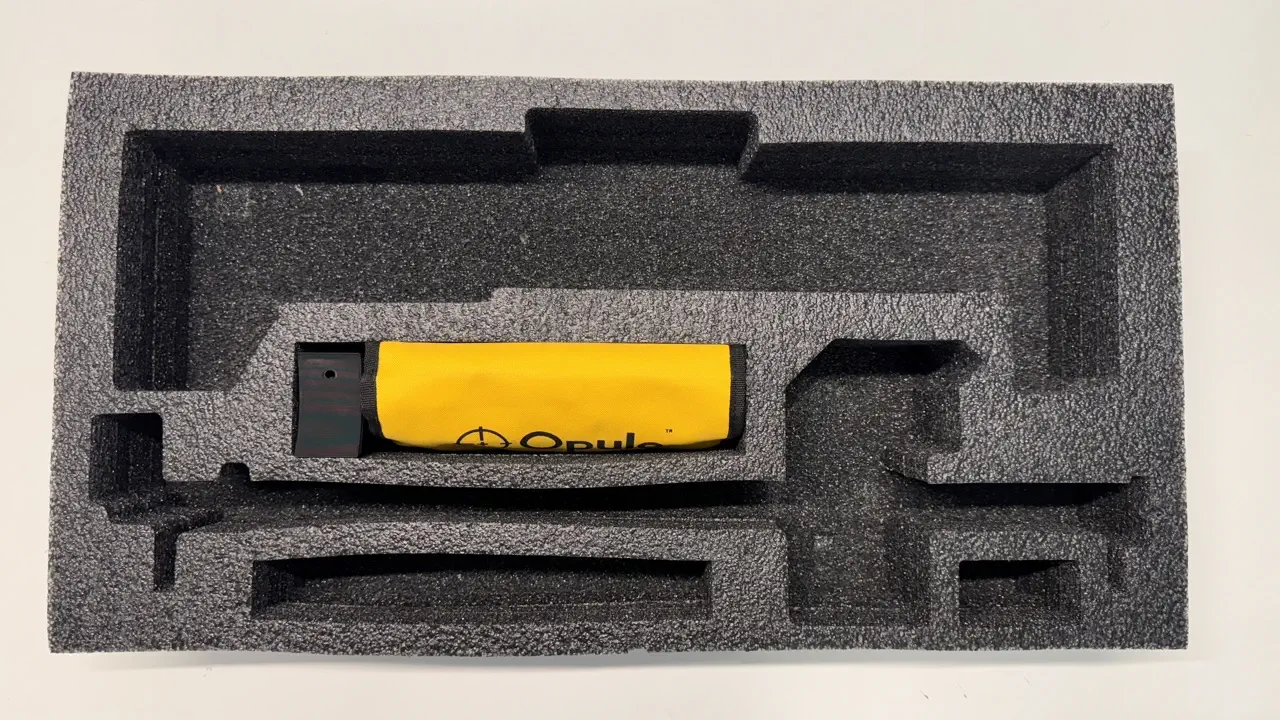
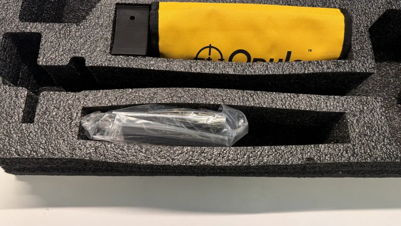
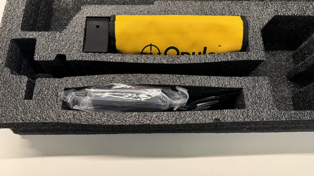
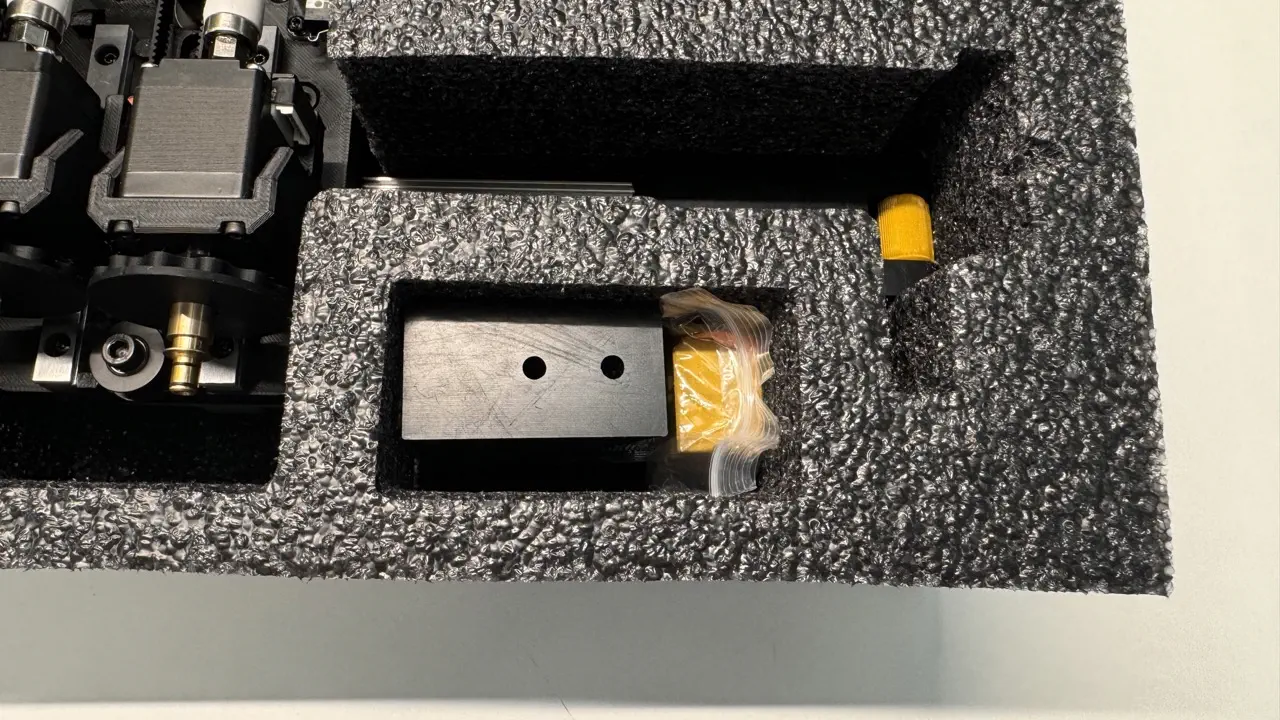
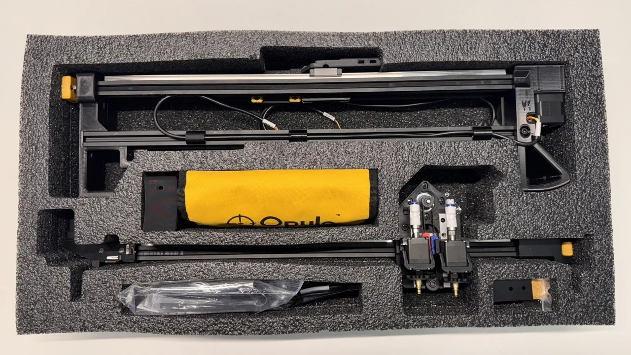
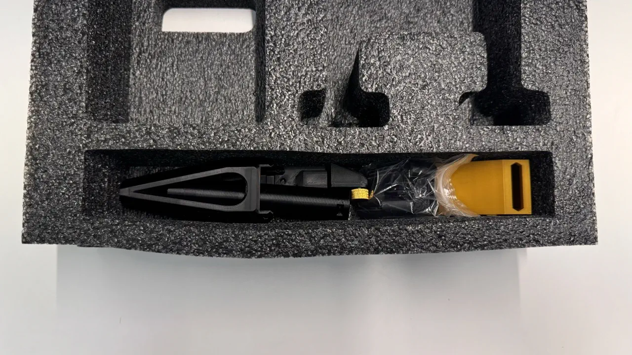
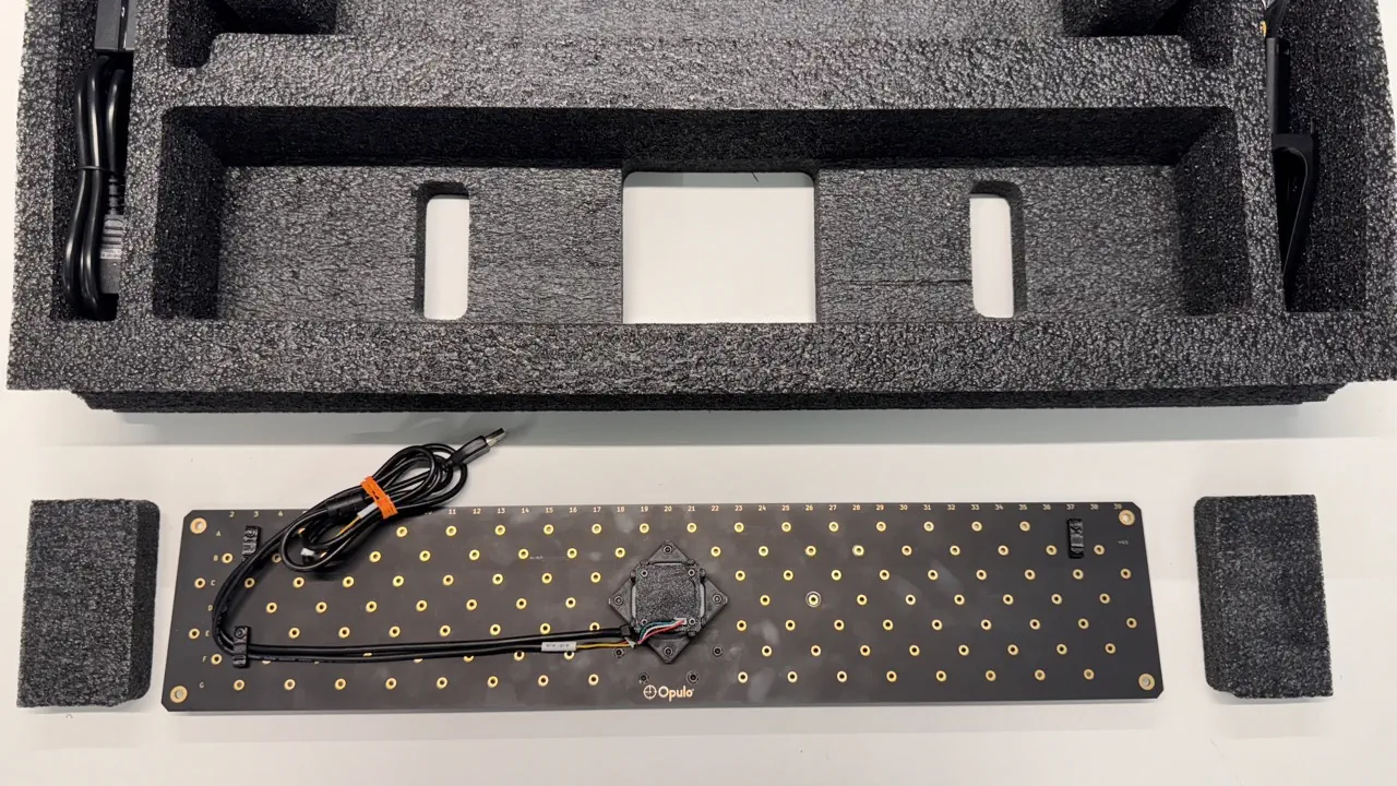
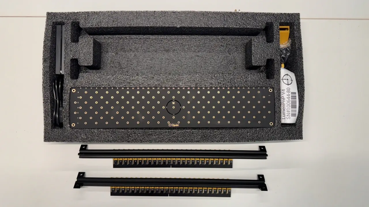
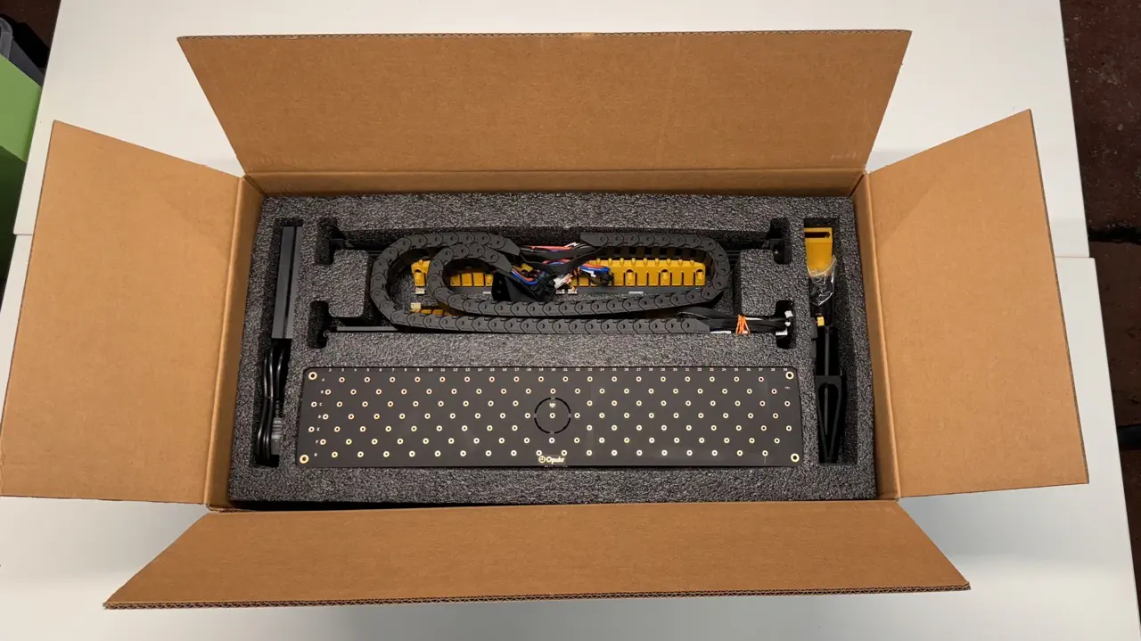
Confirm the contents of lower-foam-tray
Confirm the lower-foam-tray matches the image shown below before continuing:
Package upper-foam-tray
The following steps must be conducted by someone other than the original assembler.
misc. parts
-
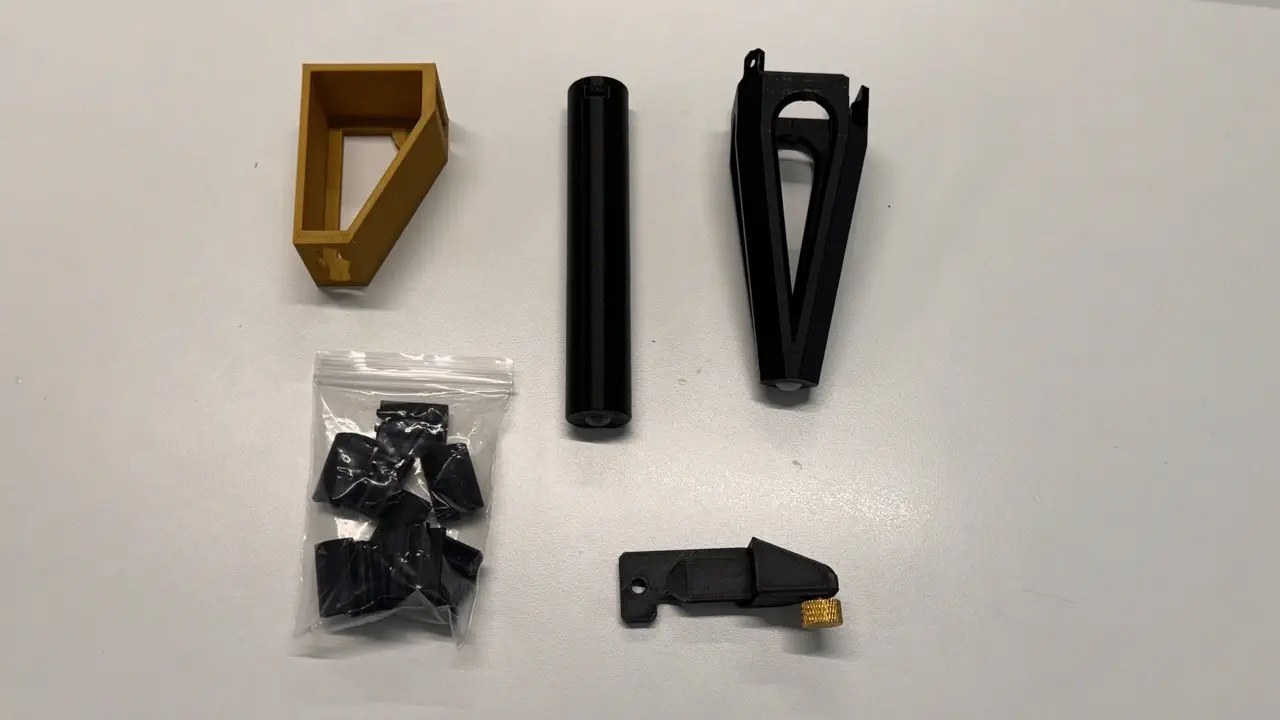
Insert the following items into the right-side pocket of
upper-foam-trayPackage each of the following items while inspecting them for their given QC inspection criteria
squaring-bracket- confirm print is latest revision (gold PLA & hex wrench feature)y-limit-striker- confirmM5-thumb-screwis installed and appears to stick-out1.5mmaux-staging-plate-foot- confirm top-side M3 bolt and bottom-siderubber-footstatic-camera-foot- confirm bottom-siderubber-footbagged-10x-extrusion-cable-clips- Only pull these items from a green QC-Pass bin.
-
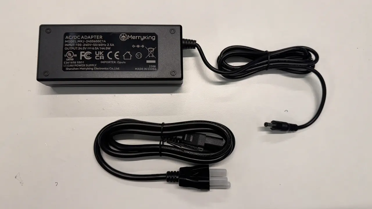
Insert the following into the left-side pocket
24v6A-power-supply(unboxed)power-cable
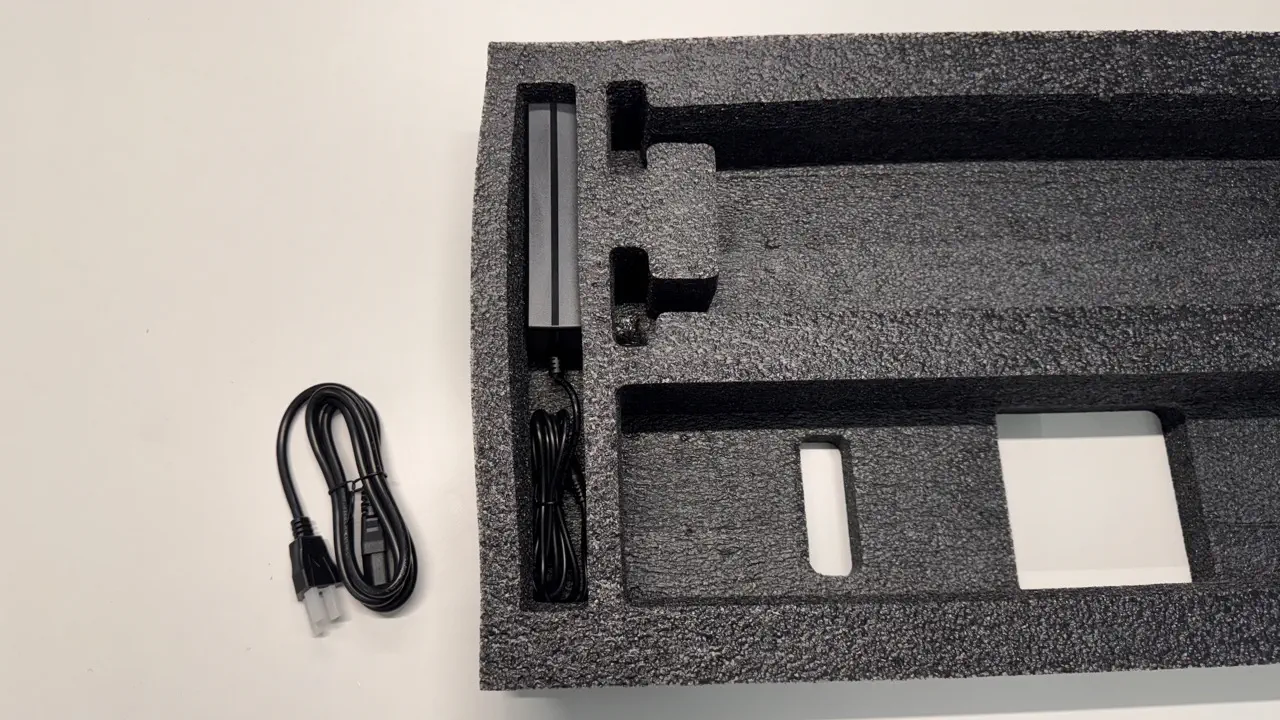
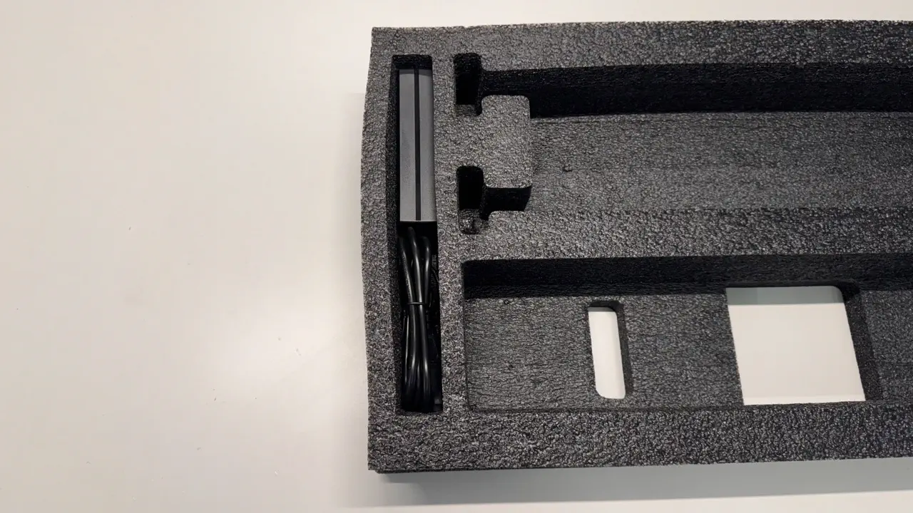
-
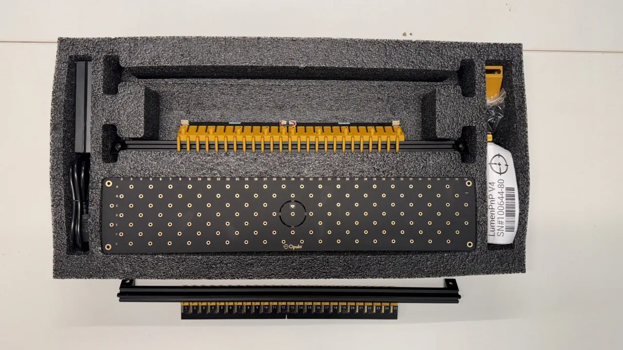
Confirm the left and right side pockets match the image below before continuing

primary-staging-plate
-
Inspect
primary-staging-platebefore packaging it into the foam tray- Review the
primary-staging-platefor the presence of all major componentsdatum-boardbottom-camera-assembly(with lens cap removed)- 3x
peek-cable-clamp bottom-light-harnessandbottom-camera-harnessw/proper cable managment- Ensure that the
bottom-camera-harnesswas used and NOT the longertop-cable-harness peek-cable-clampin A3, E3, and A37 — and rubber-band for securing loose cables
- Ensure that the
- Review the
-
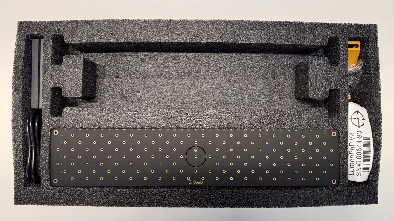
Place the
primary-staging-plateintoupper-foam-trayin the region shown belowThe Opulo logo should face away from the
feeder-railpocket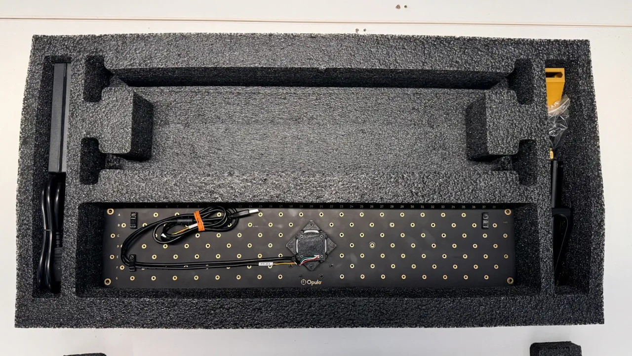
-
Insert a foam block above each side of
primary-staging-plate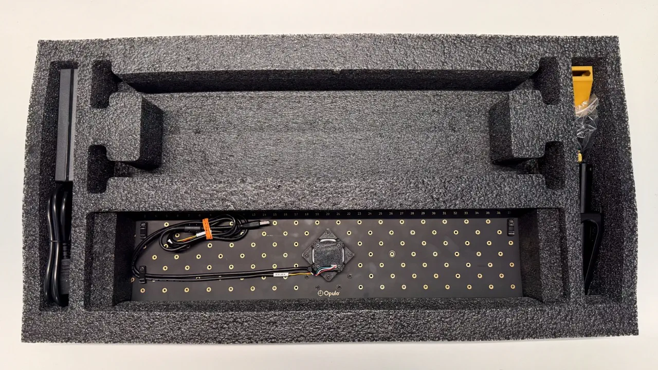
control-box
-
Insert
control-boxon right-side ofbottom-camera-assembly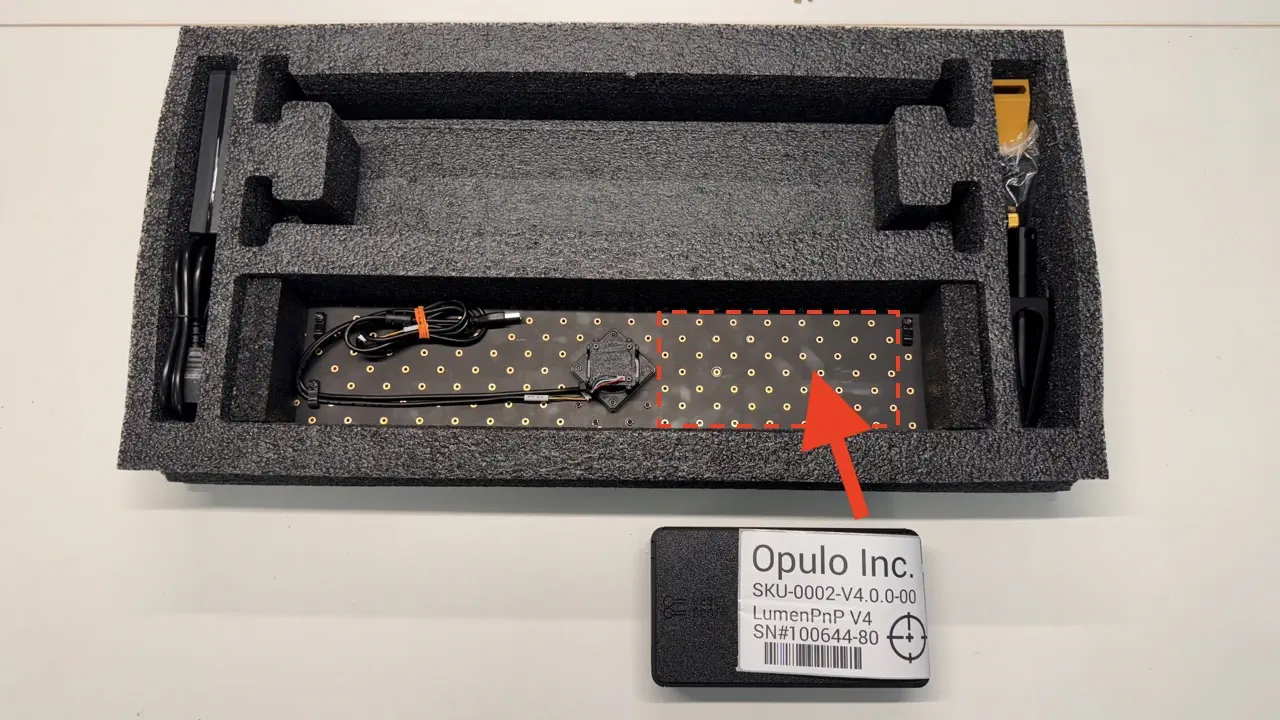
-
Unclip the
box-sn-labelfromcontrol-boxand loosely add it to right side accessory pocket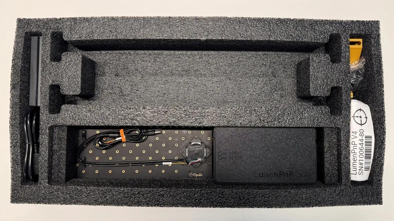
aux-staging-plate
-
Insert
aux-staging-plateon top ofprimary-staging-plateThe Opulo logo should face away from the
feeder-railpocket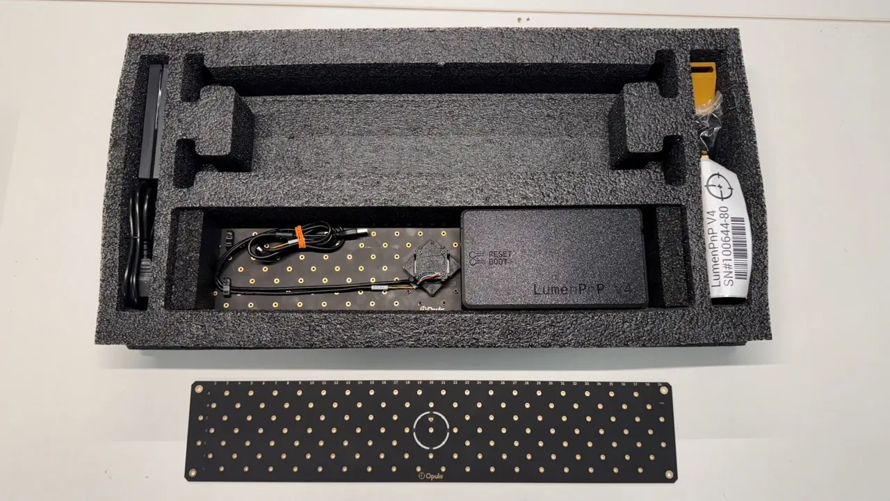
front/rear-feeder-rail
It is much easier to check the entire batch at once for a given inspection, rather than checking each one rail at a time against this entire checklist
-
Perform QC inspection on the front of
front-feeder-railandrear-feeder-railpieces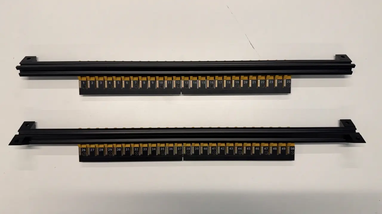
- Feeder blades are installed sequentially from left to right
- Wiggle the installed blades to ensure no screws are loose, retightening any if needed
- Ensure the print is free of defects and fits flush to
alu-extrusion - The 2x (front)/4x (rear) installed
corner-bracketpieces are flush to thealu-extrusion - Confirm a
blade-jumper-harnessis installed into eachfeeder-rail -
Use the
feeder-programmerto check that Slots#1,#12,#13, '#23',#25,#26,#37#38,#48, and#50are programmed correctlyIf all checks pass continue onward
-
Add
front-feeder-railandrear-feeder-railintoupper-foam-tray- Orient the rails back-side up, with
rear-feeder-railin the lower pocket andslot #50on the right
- Orient the rails back-side up, with
drag-chain
-
Perform
drag-chainQC- Confirm the following vacuum tubes are present at both ends:
- Red
4mm-pneumatic-tubing - Blue
4mm-pneumatic-tubing
- Red
- Confirm 3x
zip-tieused incable-splayare trimmed flush and present - Confirm presence of
top-camera-cable -
Confirm presence of
x-harnessand double check thatx-harnesshas the correct orientation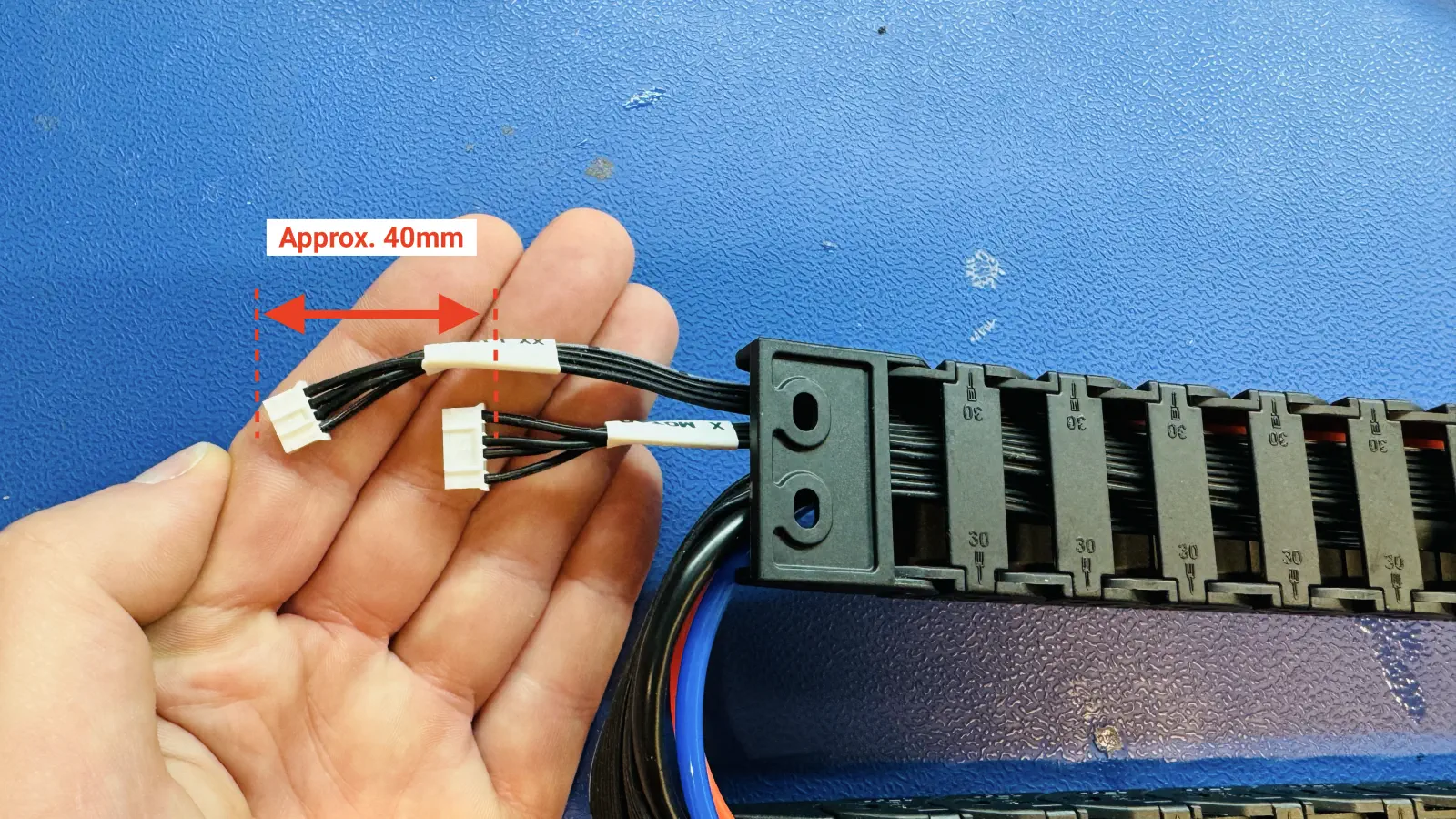
If all checks pass, continue onward
- Confirm the following vacuum tubes are present at both ends:
-
Place
drag-chainintoupper-foam-tray. Ensure the pneumatic tubing and cables are not bent or pinched.
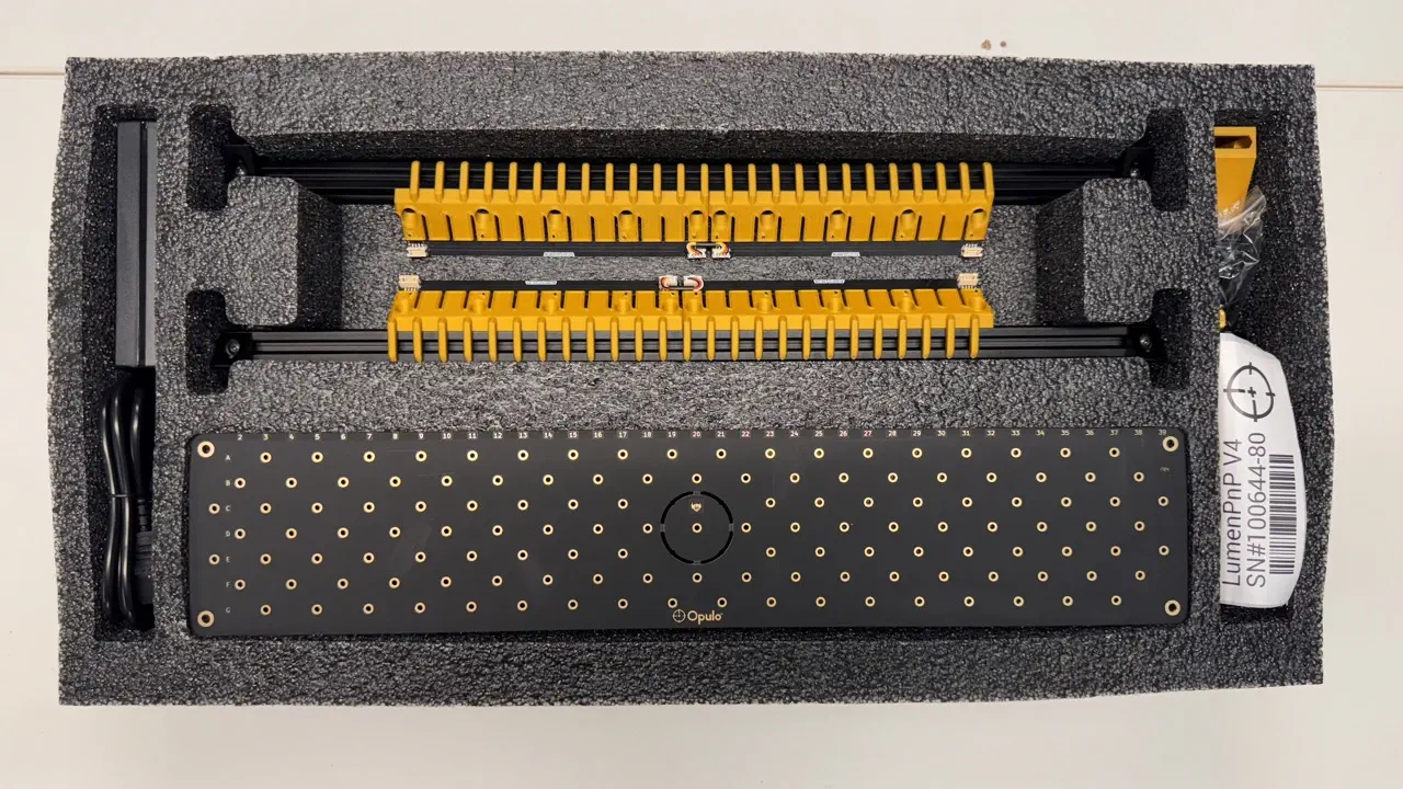
Confirm the contents of upper-foam-tray
-
Confirm the
upper-foam-traymatches the image shown below
Package LumenPnP Box
Perform this process 1 machine at a time
It's OK for this work to be performed by the original machine assembler
-
Gather the following items:
- Packaged and QC'd upper-foam-tray
- Packaged and QC'd lower-foam-tray
- Empty LumenPnP box
- All relevant shipping paperwork, including packing slip, shipping label, and any international forms
-
Examine the packing slip and take note of what (if any) additional items must be packaged. Load the additional items into a bin.
-
Open the OQC Checklist
- Fill out this checklist as you package the LumenPnP

-
Complete the first page of the
OQC Checklistpage
-
Examine the contents of the
lower-foam-trayand complete the correspondingOQC Checklistpage
-
Place the packaged
lower-foam-trayinto the LumenPnP packaging- Orient the tray so that the packaged
x-gantryis closer to the Opulo logo side of the box
- Orient the tray so that the packaged
-
If the order includes additional items, package them into the open void regions of
lower-foam-tray. You may also package items intoupper-foam-trayafter completing the correspondingOQC Checklistpage in the later steps. The image below shows commonly used regions oflower-foam-tray: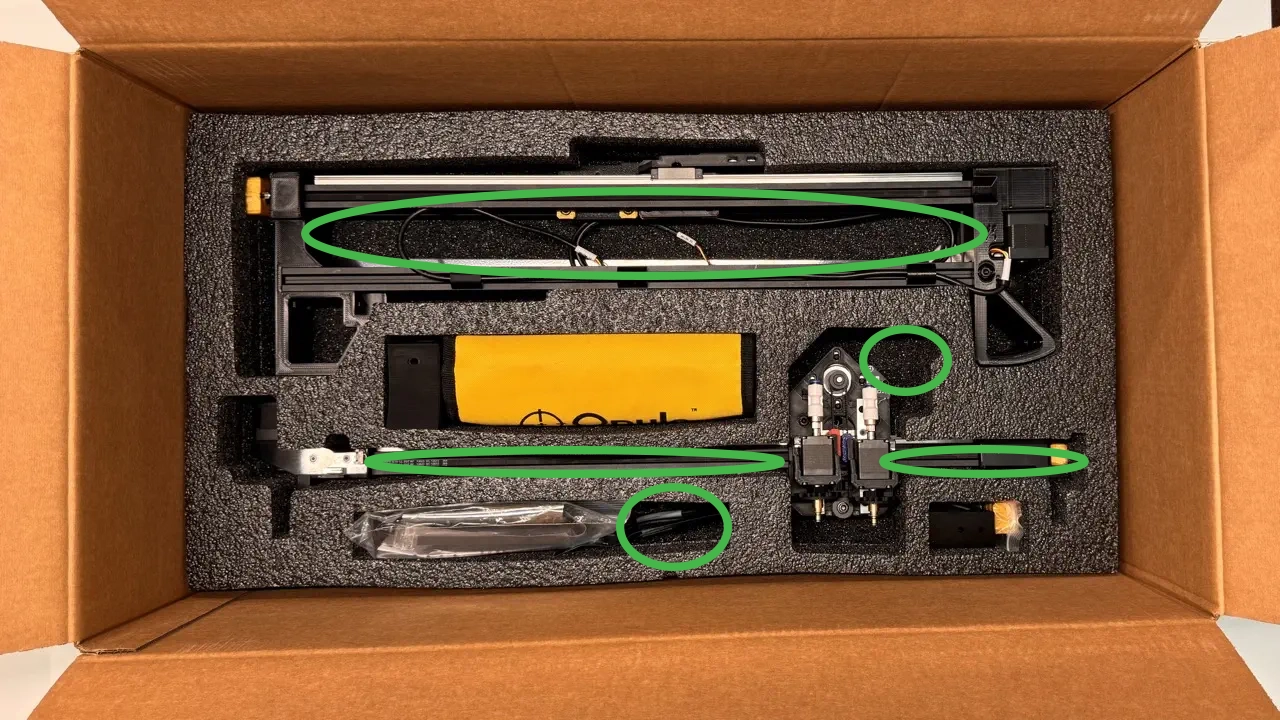
-
Examine the contents of the
upper-foam-trayand complete the correspondingOQC Checklistpage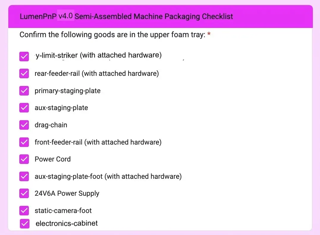
-
Place the packaged
upper-foam-trayinto the LumenPnP packaging- Orient the tray so that the staging plates are closer to the Opulo logo side of the box
-
If the order includes additional items, package them into the open void regions of
upper-foam-tray. The image below shows commonly used regions ofupper-foam-tray: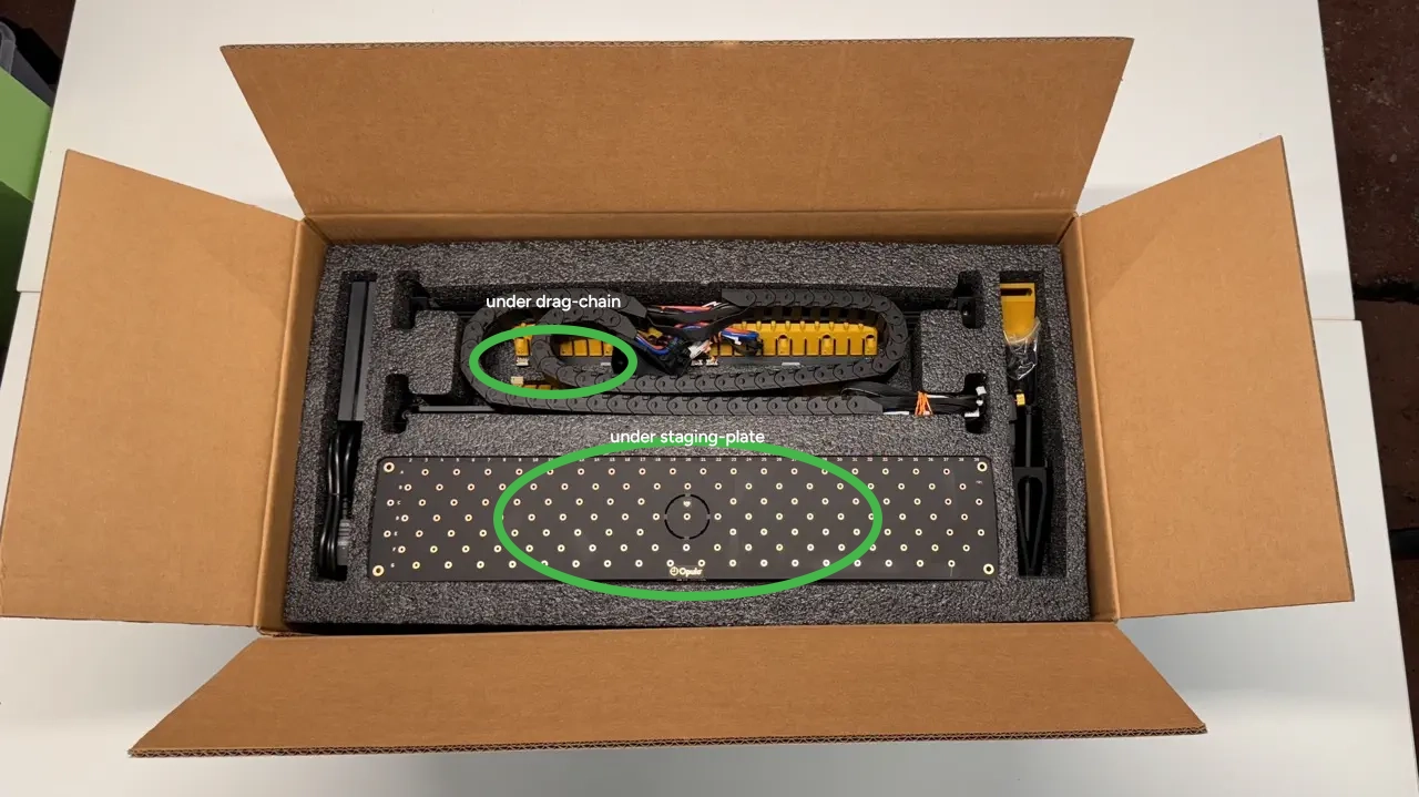
-
Complete the corresponding
OQC Checklistpage
-
If you answered
Yesto the question "Are any additional items going in the box?" you will be directed to theExtra Items Checklistpage- Check off any additional items this order contains before proceeding
If the order includes
feedersor items suitable for afeeder-accessory-traypackage them above theupper-foam-traylike so:
Use the following guide to help you decide how to pack
feederswith aLumenPnP:
- Check off any additional items this order contains before proceeding
-
Print out a
getting-started-cardwith the machine'sversion number
-
Peel the wax paper off the back of
getting-started-cardand adhere it totop-foam sheet- Orient the card so that it's bottom edge faces toward the Opulo logo side of the box
If the order being packed included feeders, attach the feeder
getting-started-cardon top of the top sheet as well
-
Proceed to the
Finalize Shipmentpage of theOQC Checklistand work your way through alongside following these last steps
-
Tape the LumenPnP box shut
-
Adhere
box-sn-labelto the LumenPnP box in the region showed below:
-
Ahere shipping documents to box
- Adhere all relevant shipping documentation to the top left side of the LumenPnP box flap
- Set the packing slip aside if it lists product pricing information, otherwise it can be adhered below the shipping label
-
Adhere
fragile-stickerto the bottom right corner of the box.
-
Click
Submiton the final page ofOQC Checklistpage
The LumenPnP should now be ready for fulfillment!