Index
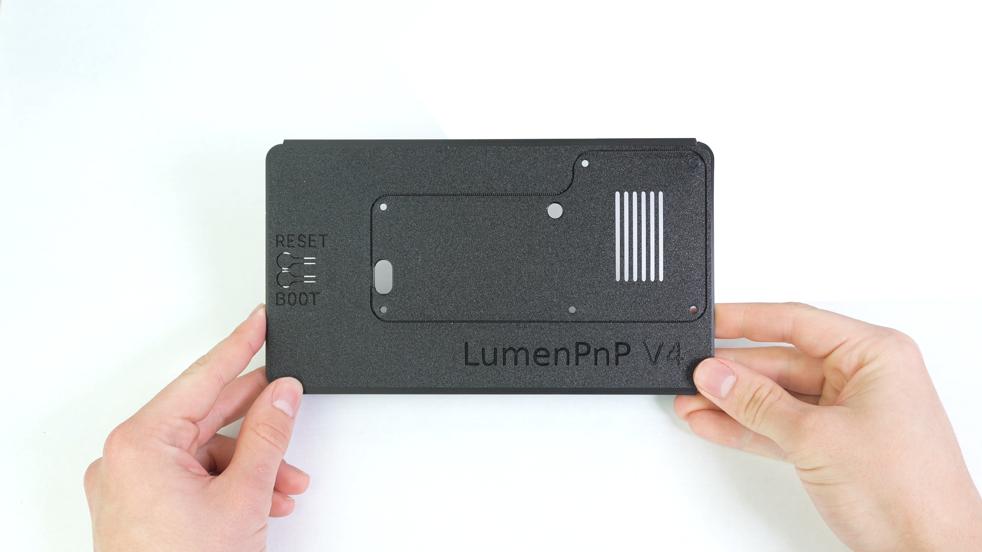
Step 1 of 13
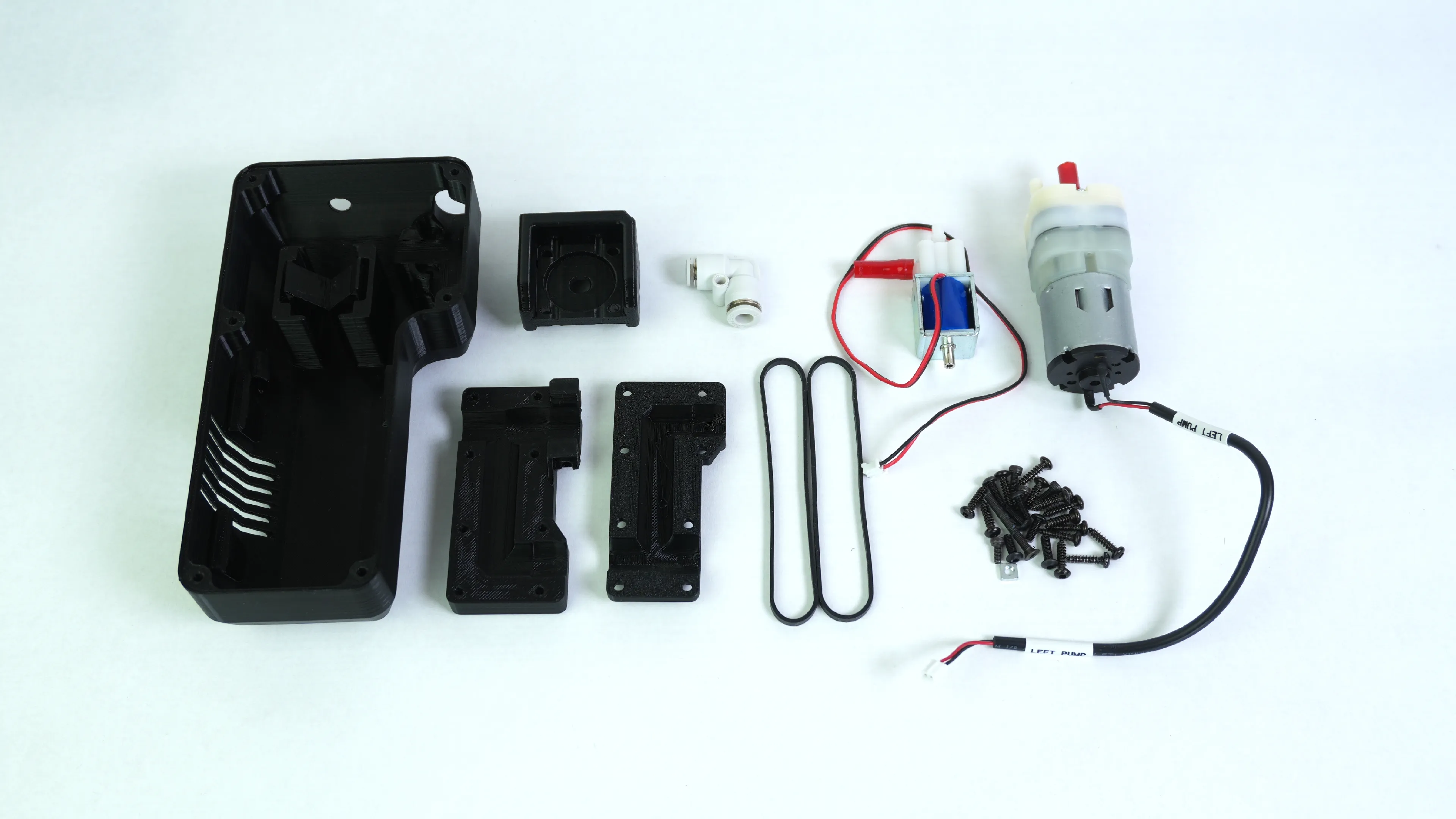
Parts Needed:
-
3D Printed Parts
- Tool Head Stepper Mount
- Auger Tool Head Mount
- Auger Clamp
- Air Assist Container
- Air Assist Lid
-
Main Components
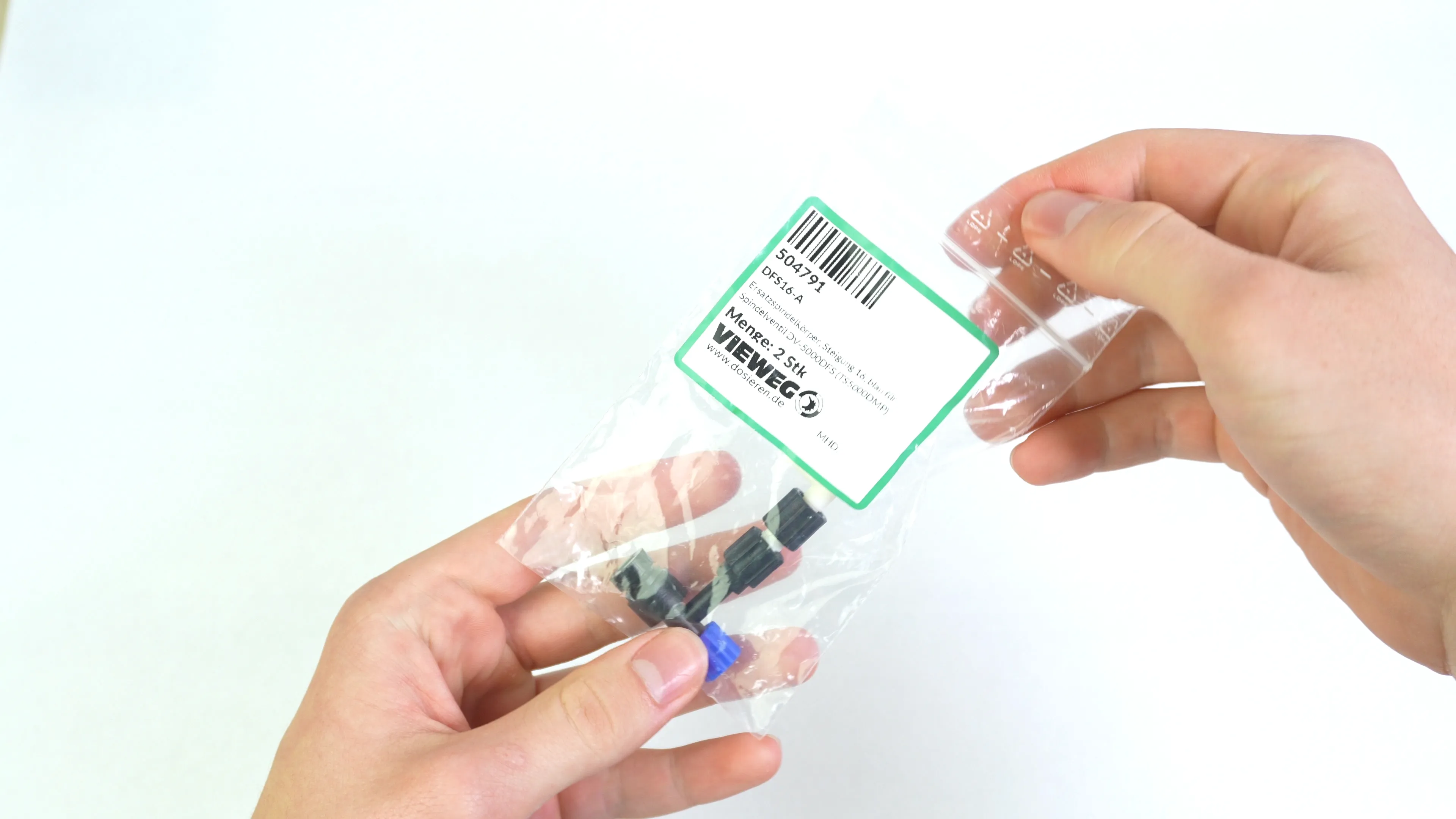
- 16-Pitch Auger
- Luer Lock Extender
- Solonoid Valve
- Vacuum Pump
- Right Angle Air Fitting 6-4mm
- 16mm Soft PVC Tubing Red 6x4
- 20mm Soft PVC Tubing Red 6x4
- 2X Silicone Rubber Band
-
Hardware
- 3X 5x6x.42mm Aluminum Shim
- 5X M2.5x6mm Socket Head Screw
- 14X M3x12mm Self Tapping Button Head
- 3X M3x10 Button Head Screw
- 4X M3 Square Nut
- 1X M3x18mm Button Head
Step 2 of 13
Preping Container
-
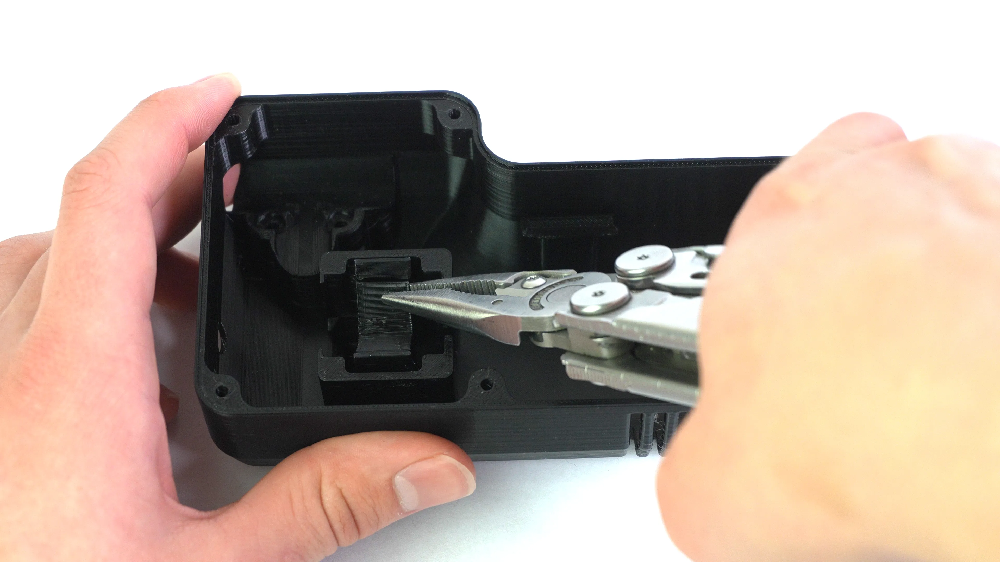
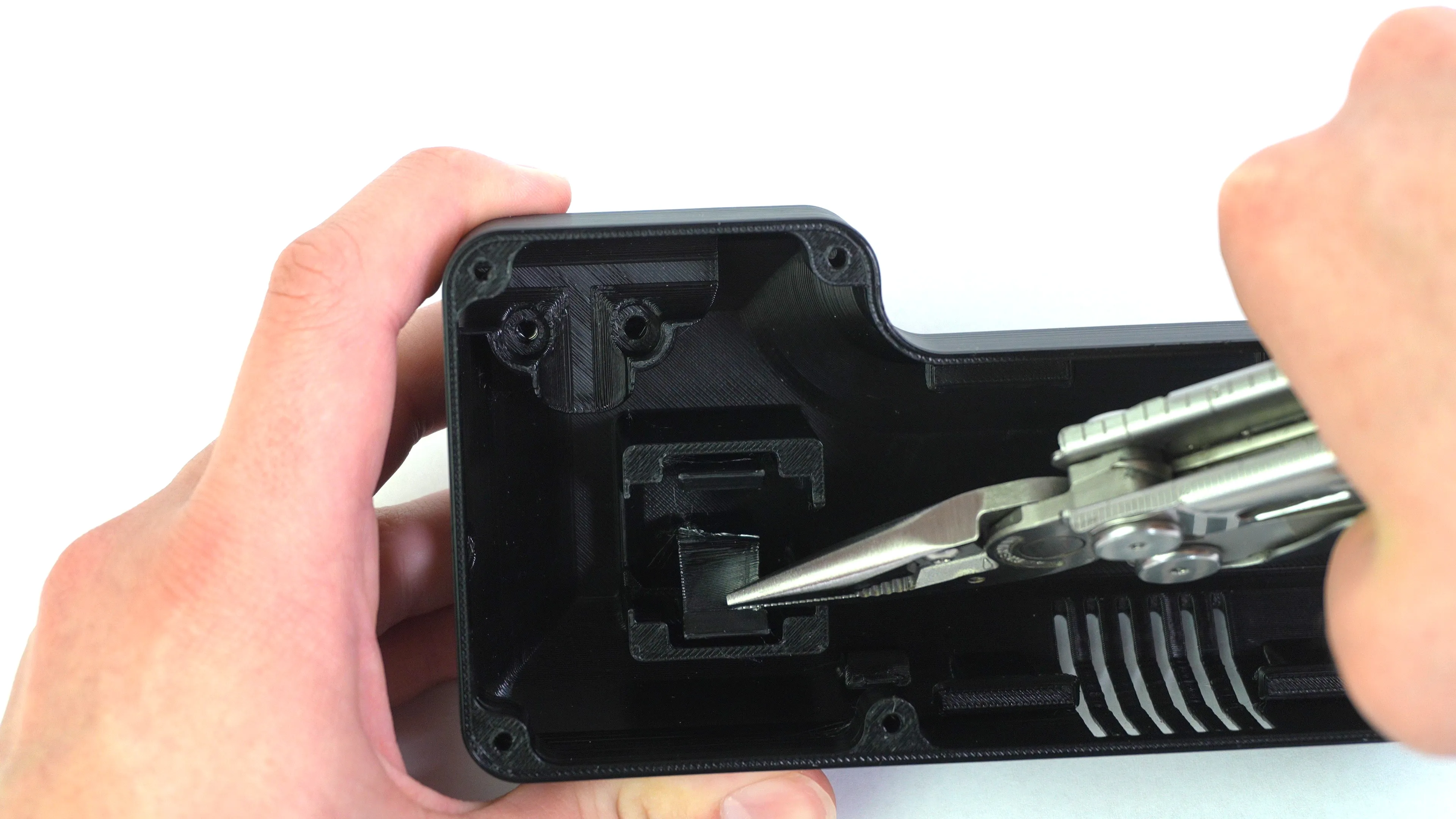
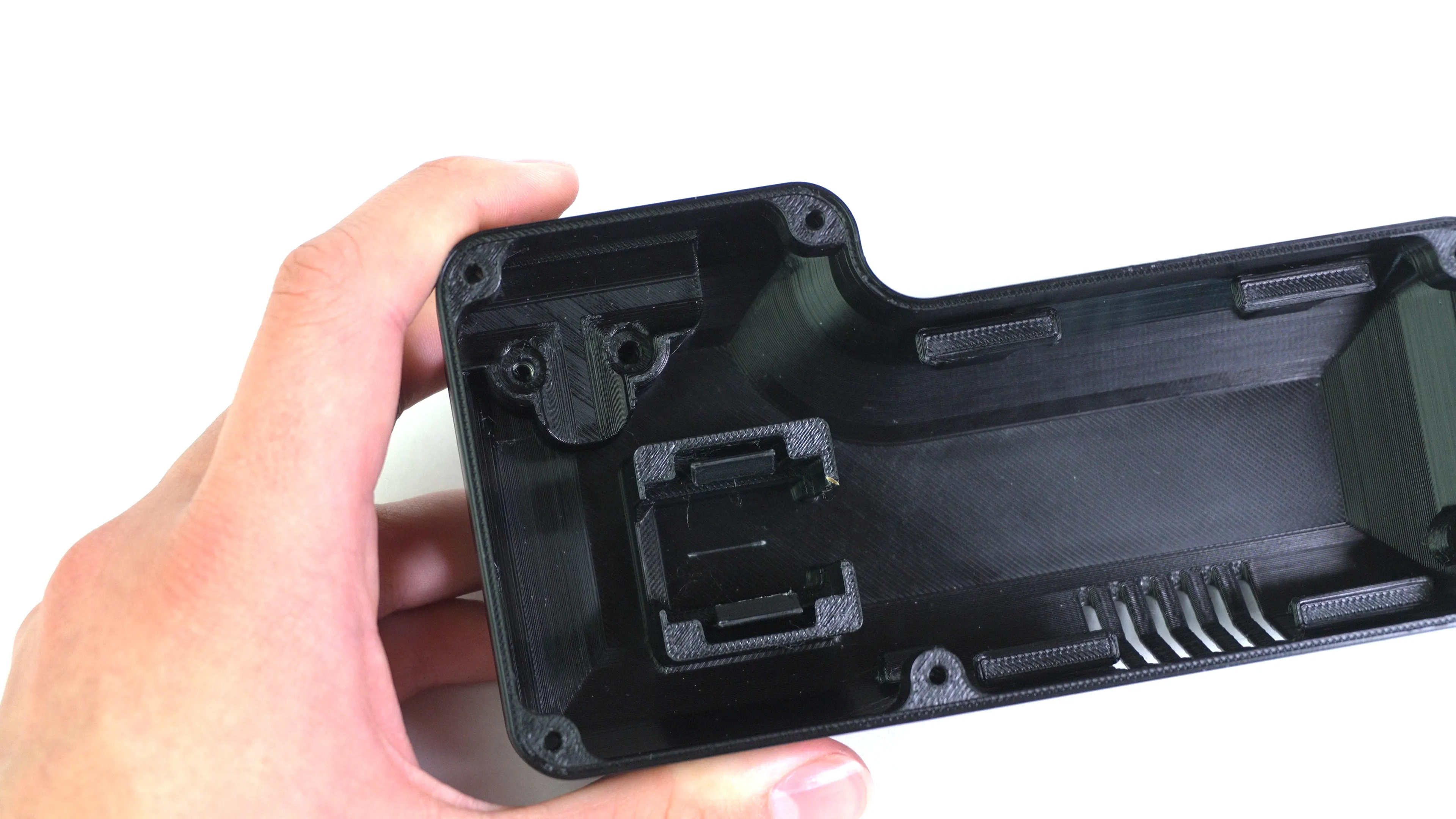
Grab an air assist container and a pair of needle nose pliers. Remove the support under the solenoid clips.
-
Be sure to grab the support as close a possible to the container clips and body to minimize left over support after removal.
-
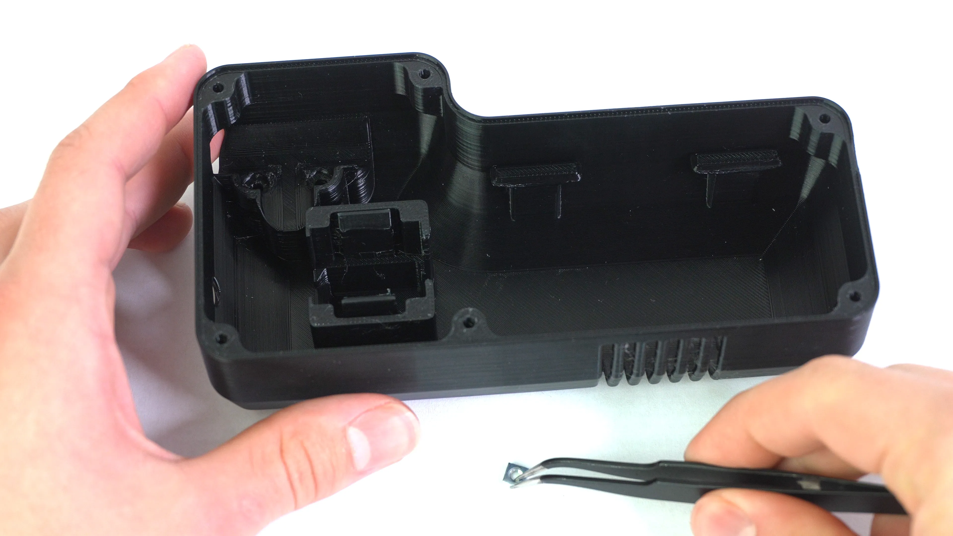
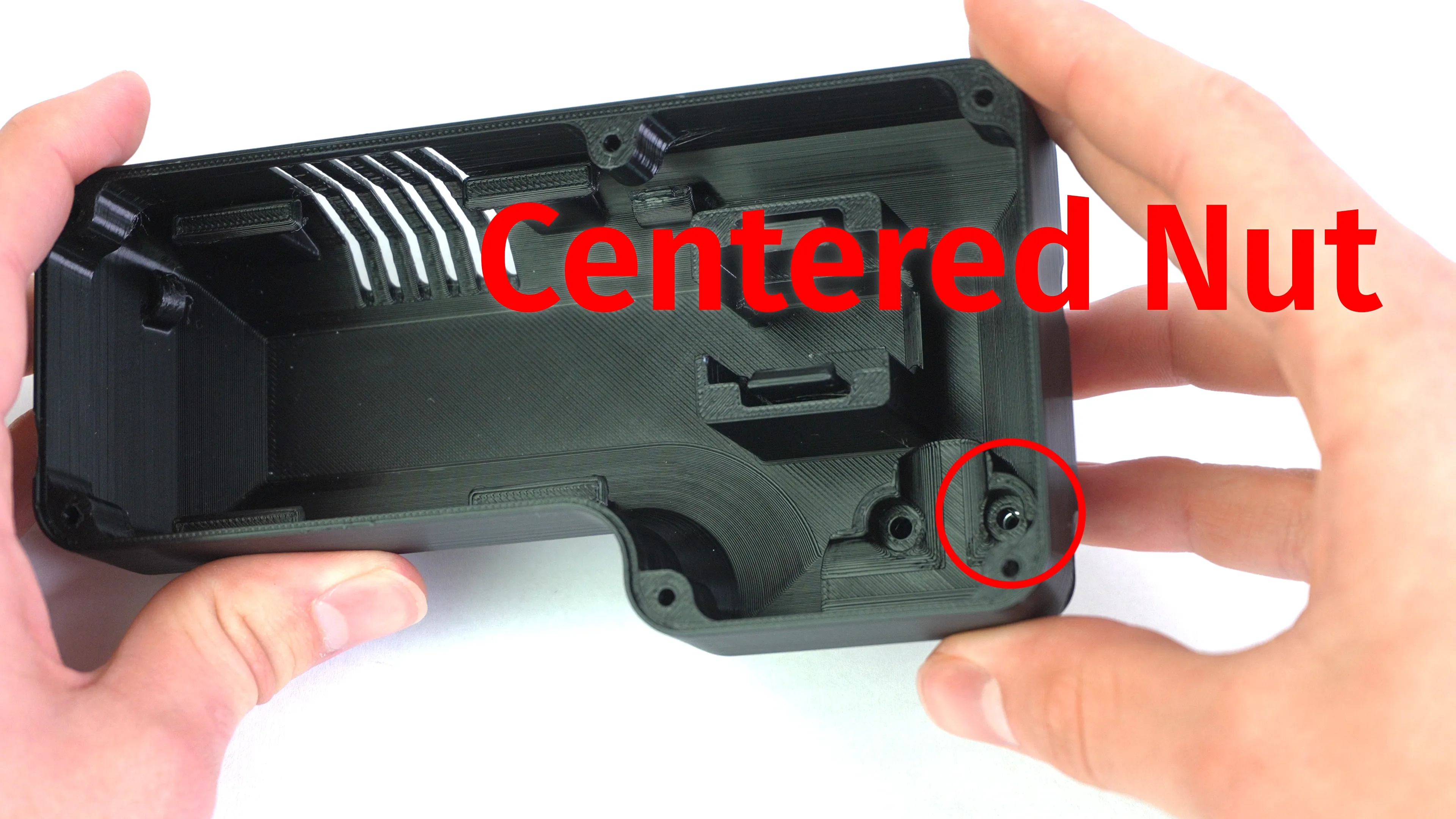
Pick up one M3 square nut and insert it into the far corner of the air assist container.
-
Make sure visually that the nut is centered within the pocket.
Step 3 of 13
Preping Solonoid
-
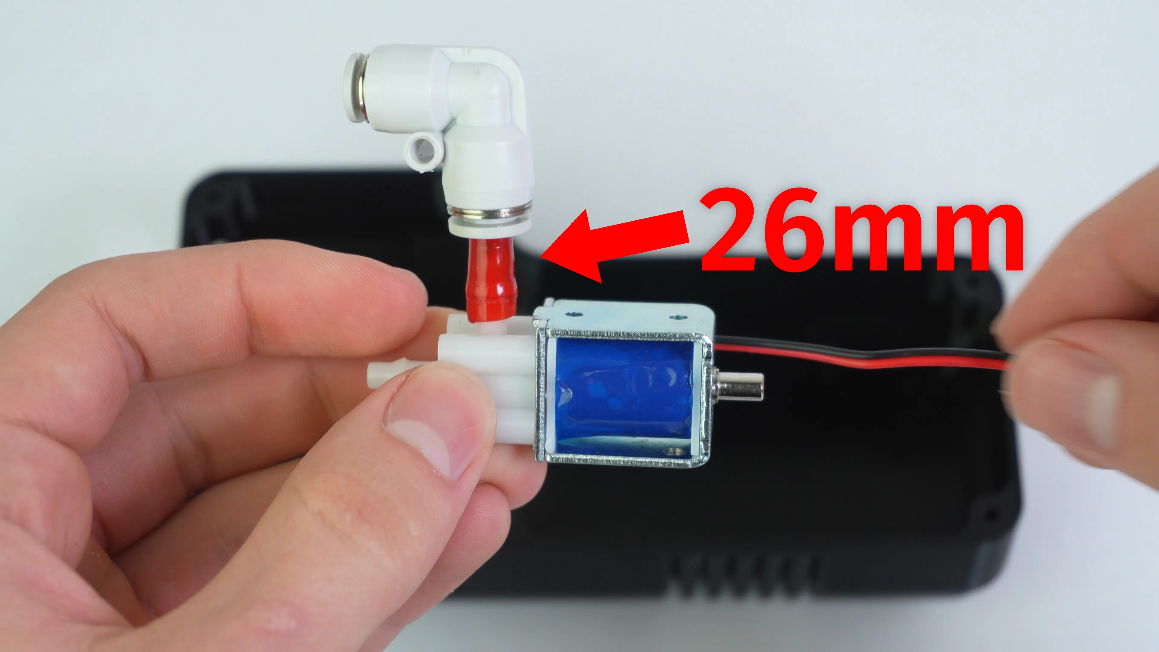
Slip a short section of tubing 26mm on the barb fitting that is ajacent to the metal one. Then, connect the right angle reducer fitting with the larger connector side to the other end of the tubing.
Step 4 of 13
Installing Solonoid
-
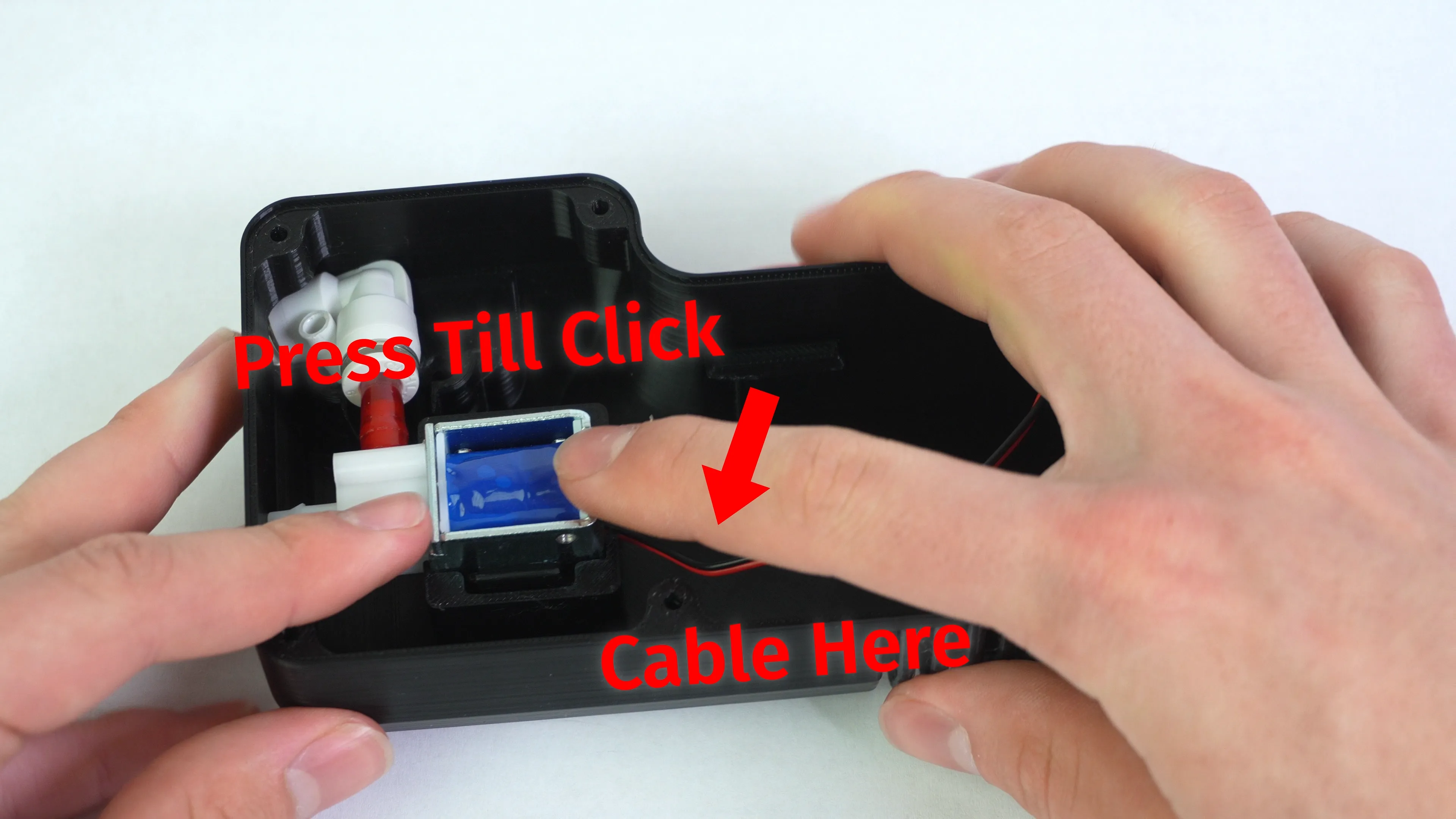
Put the reducer fitting loosly in the corner and press the solonoid into the clips with the only plastic barb exposed pointed at the wall of the container where the hole is. Push the solonoid until you hear a click.
Guide the Wire
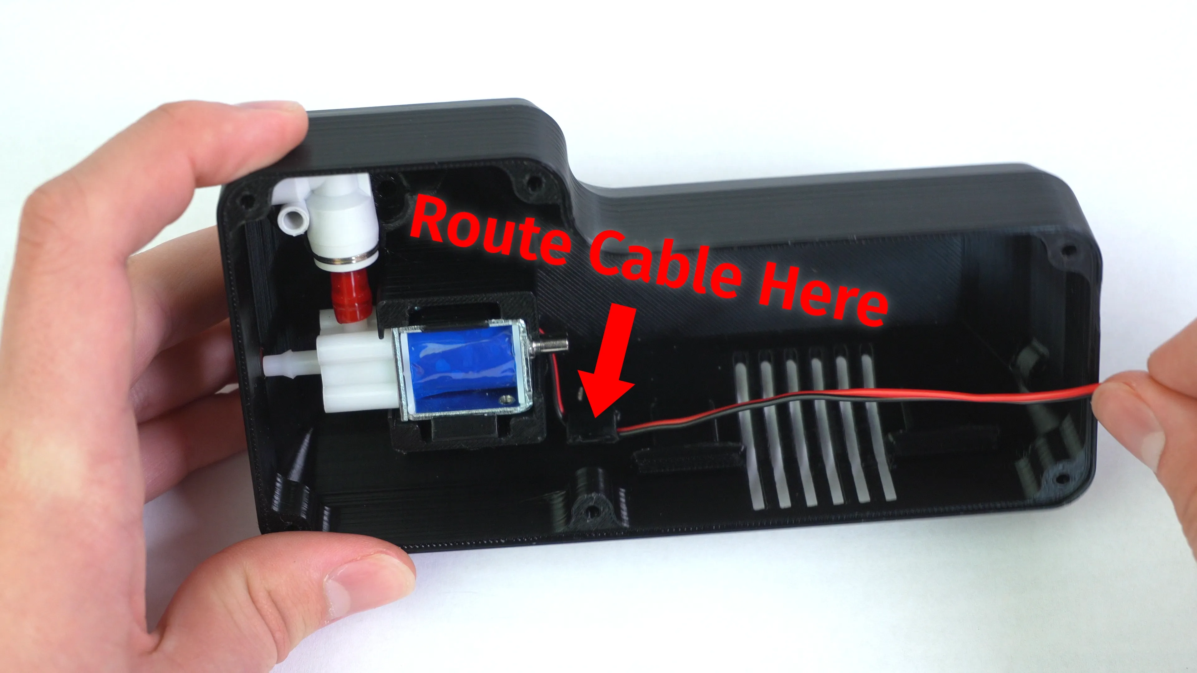
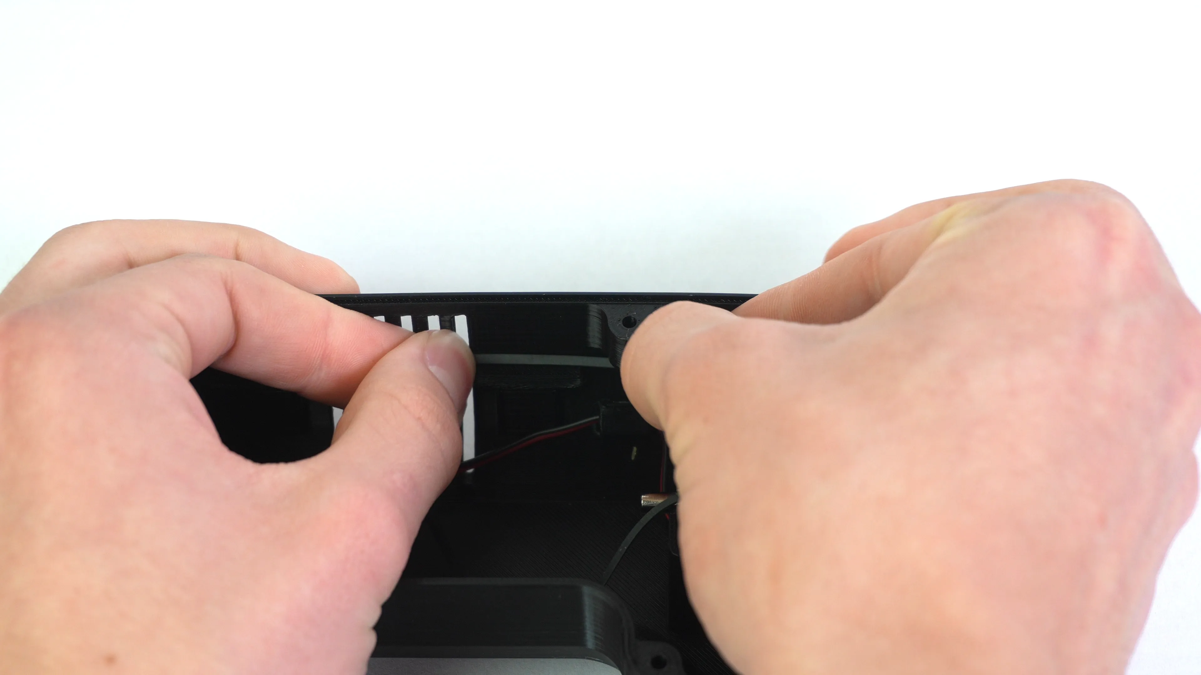
Be cognizant about tucking the wire of the solonoid towards the metal tube fitting and away from the walls of the solonoid mount to prevent pinching during assembly.
-
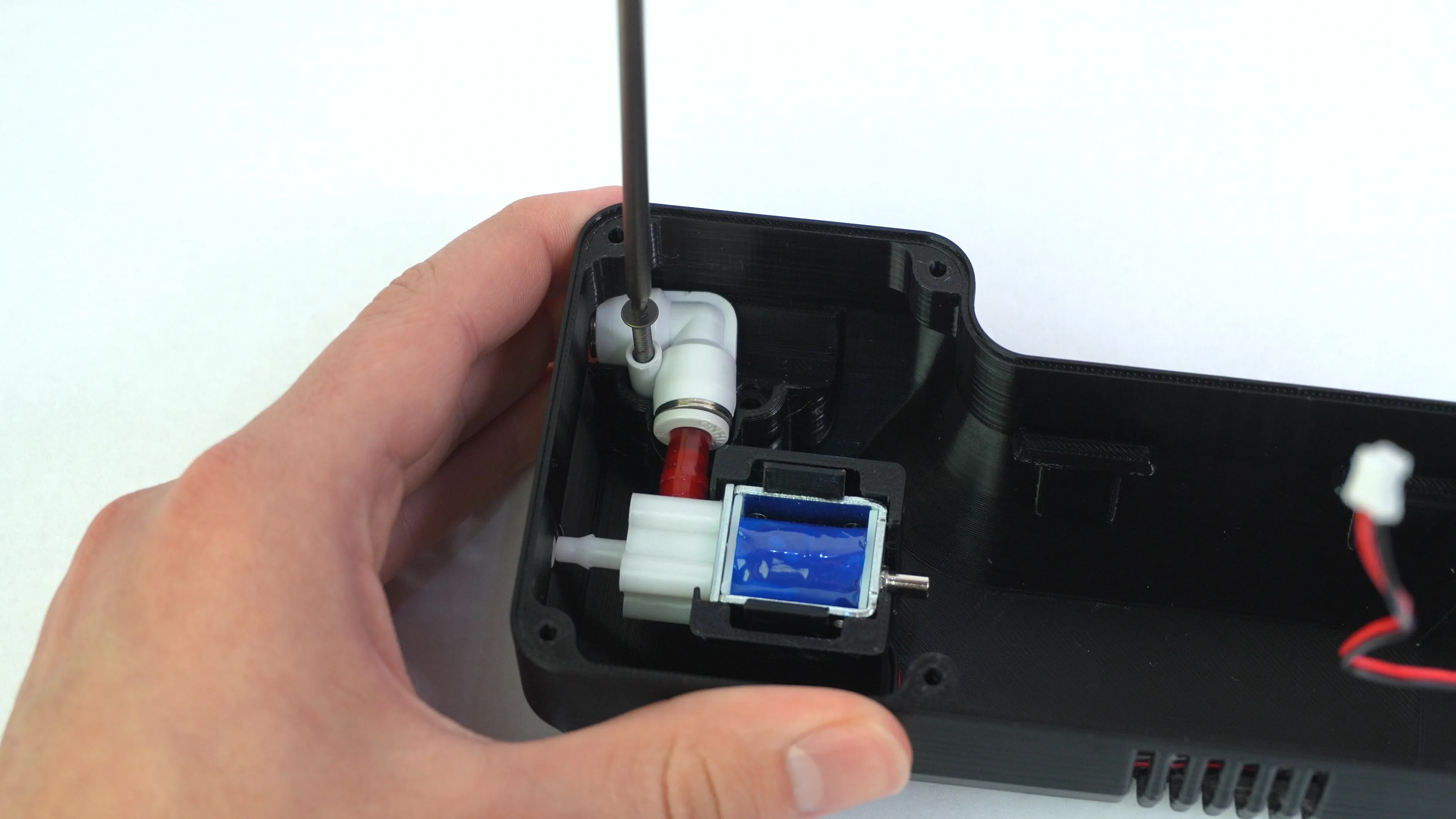
Use an M3x22mm flat head screw to secure the right angle air fitting.
-
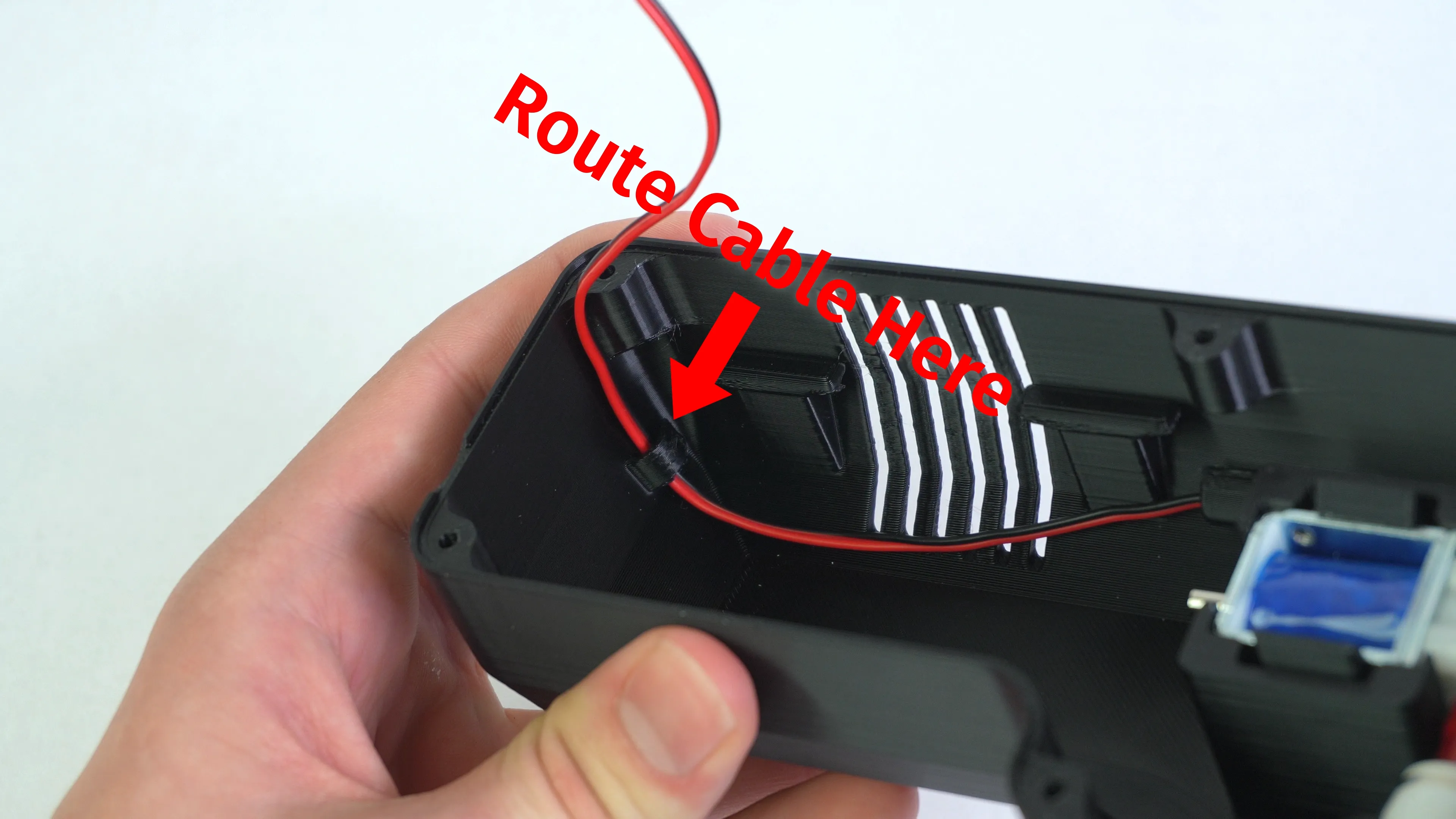
Guide the wire around the first cable clip.
-
Guide the wire around the second cable clip.
Step 5 of 13
Installing Air Pump
-
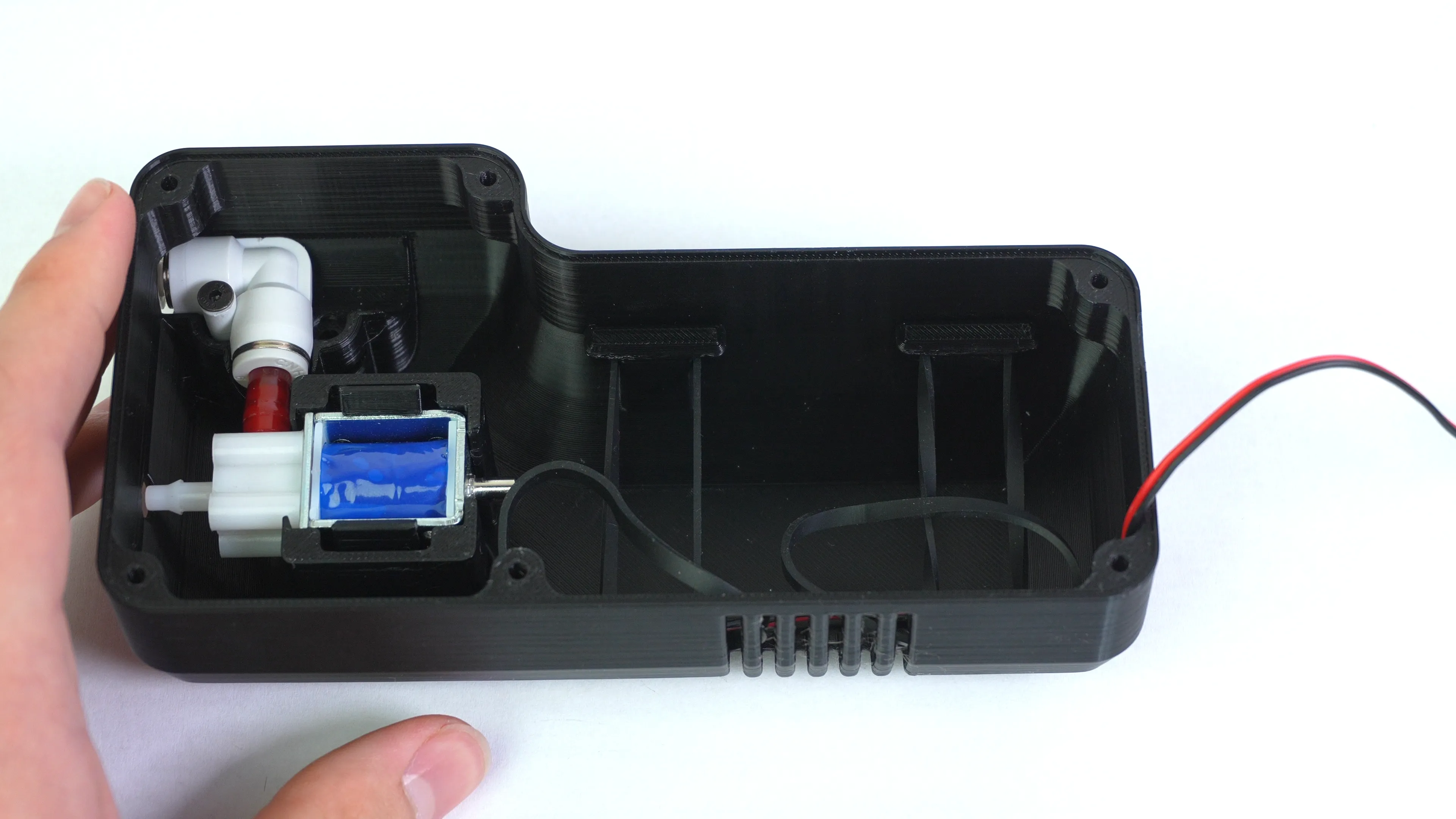
Strech a silicone rubber band over one of the vacuum motor posts.
-
Twist the rubber band and stretch it over to the other side
-
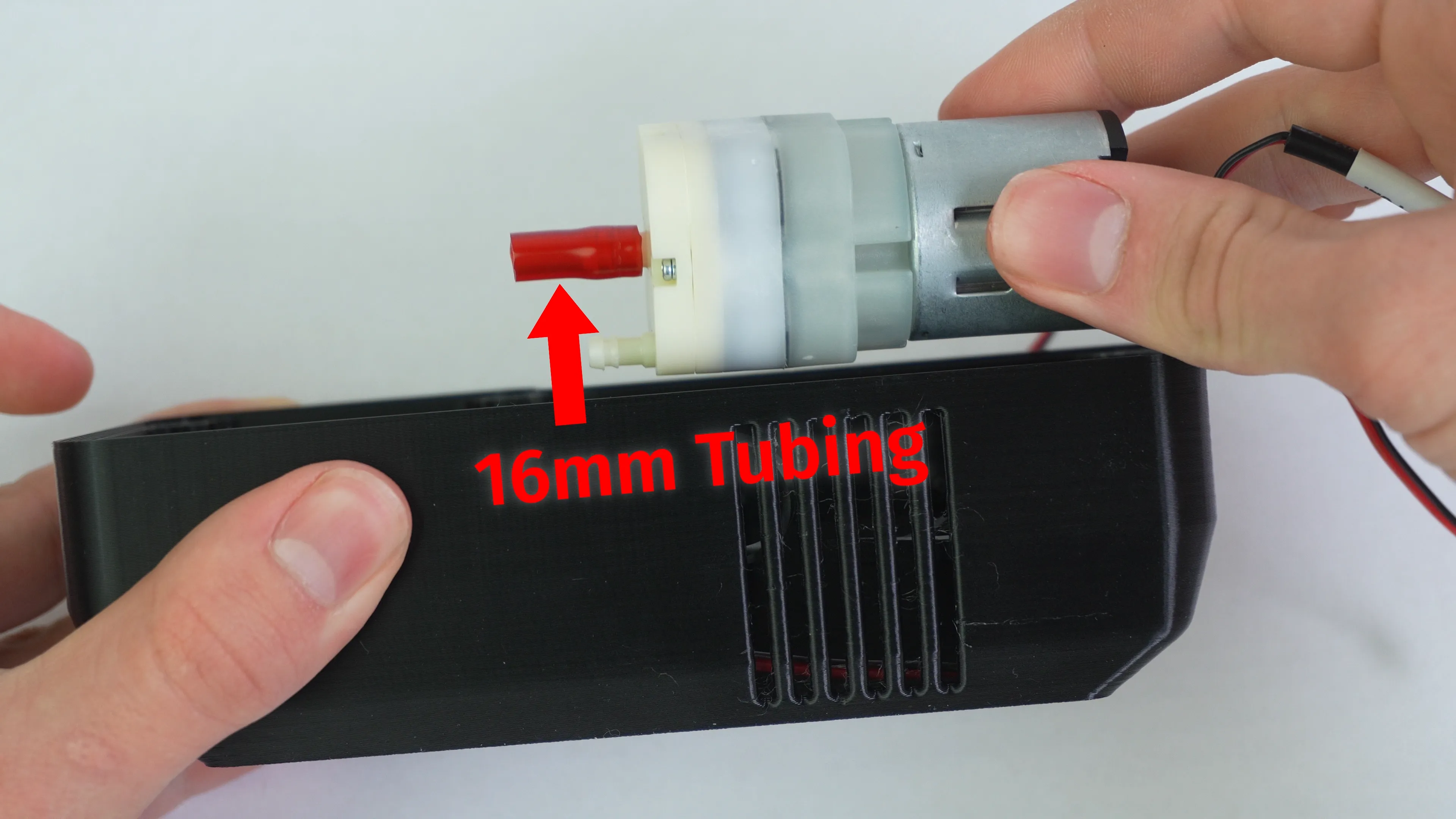
Install a 16mm piece of tubing onto the center barb fitting of the vacuum motor.
-
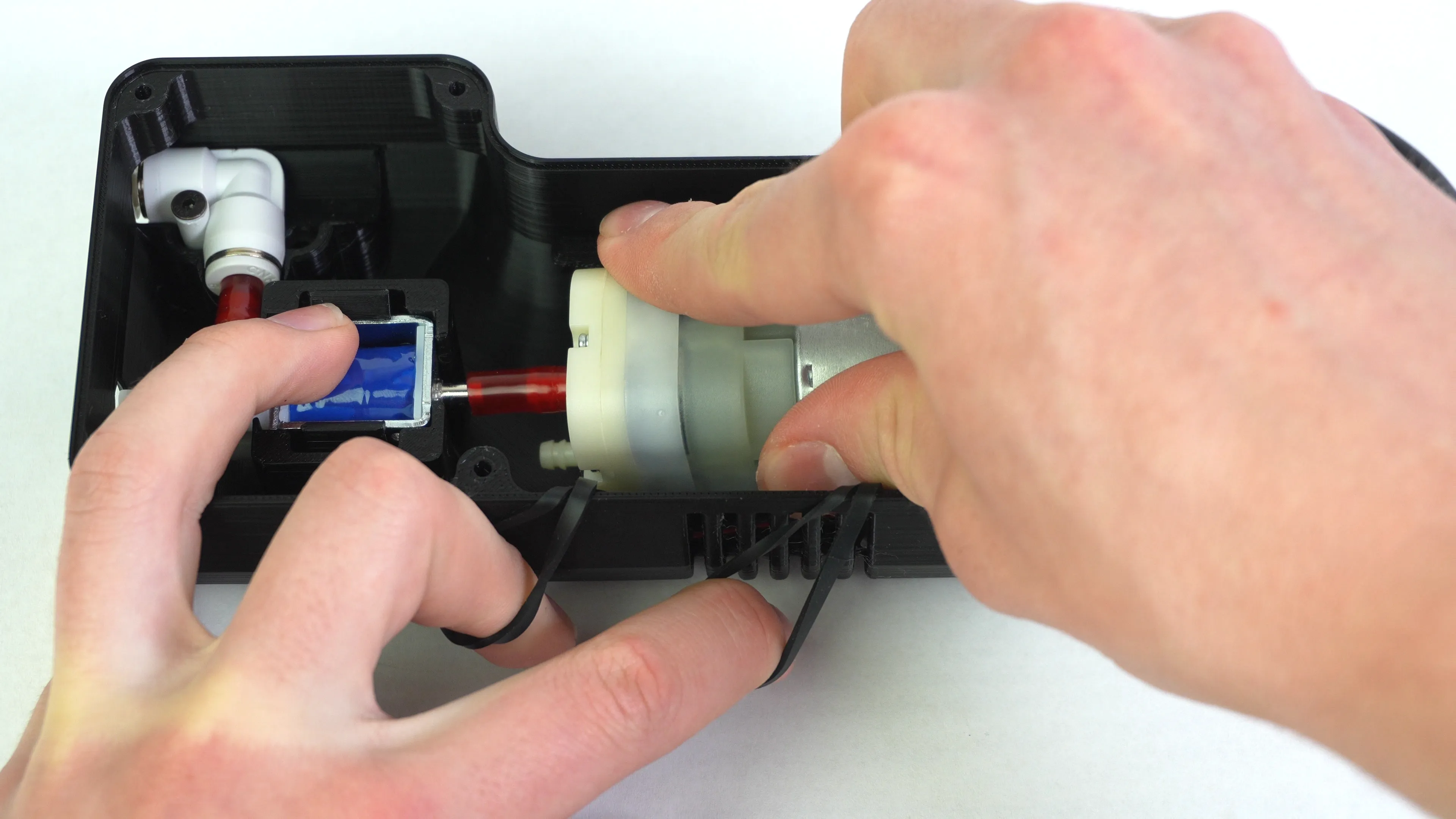
Angle the vacuum pump and connect it to the metal barb of the solonoid valve. Then, lay it across the rubber bands.
-
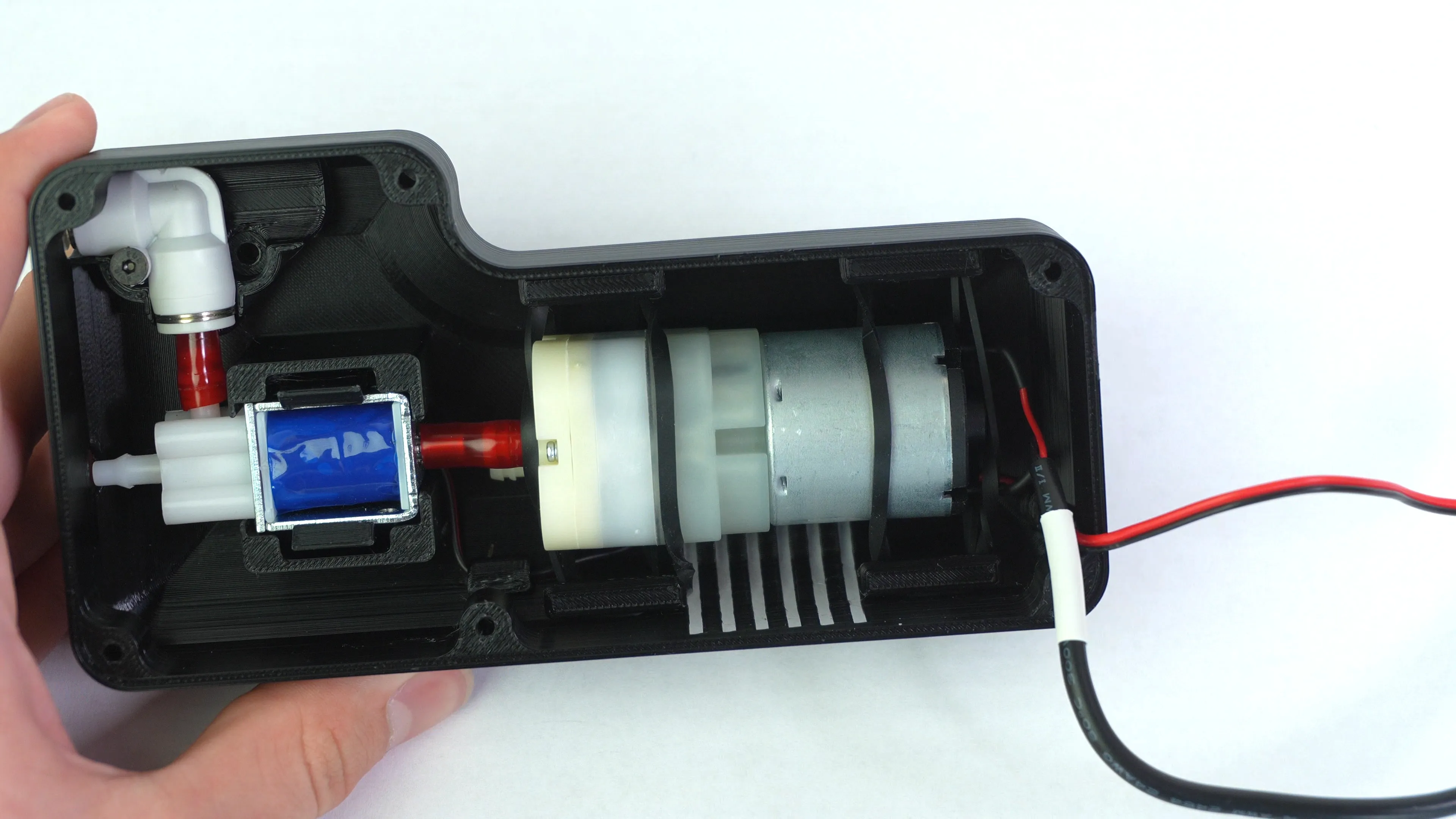
Finish mounting the motor by connecting the free rubber bands accross the motor to their respective rubber band mounts.
Step 6 of 13
Assembling Lid
-
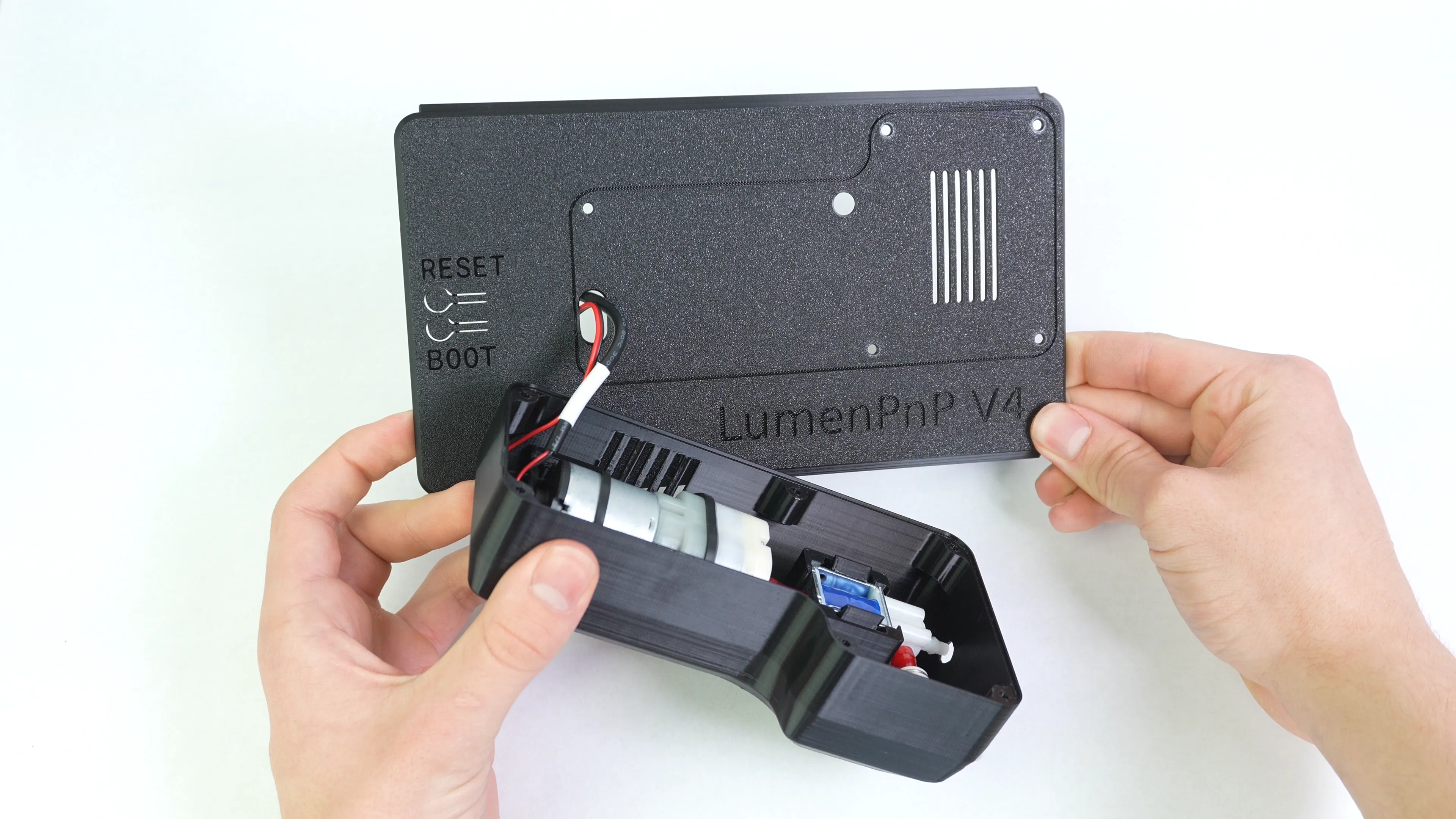
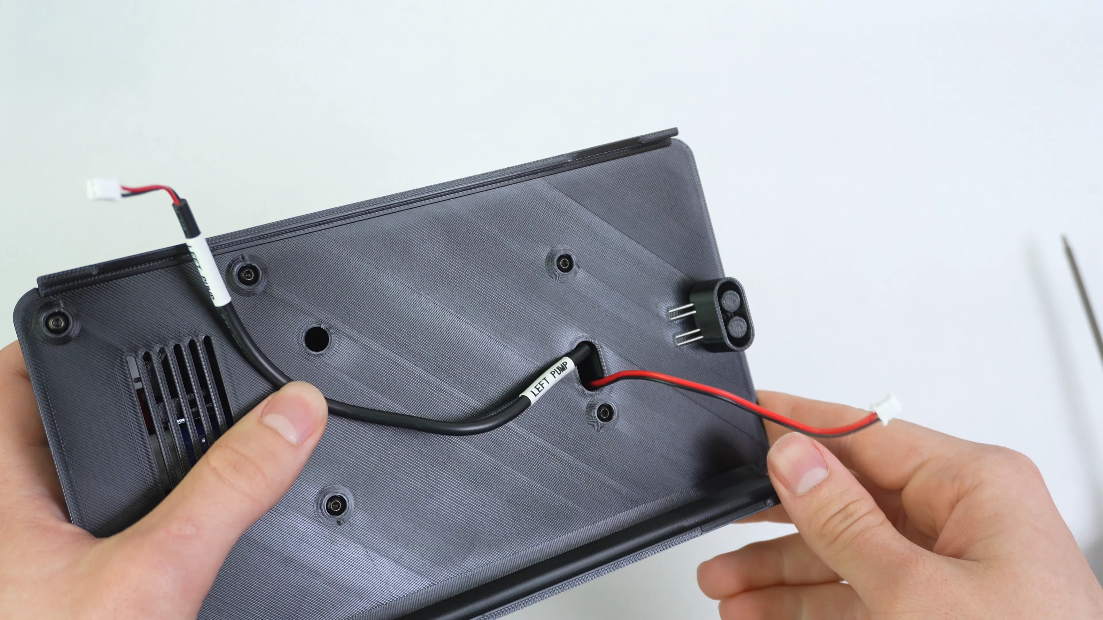
Pass the vacuum pump and solonoid valve wires through the control box lid
-
Align the air assist container lip with the control box lid grove.
-
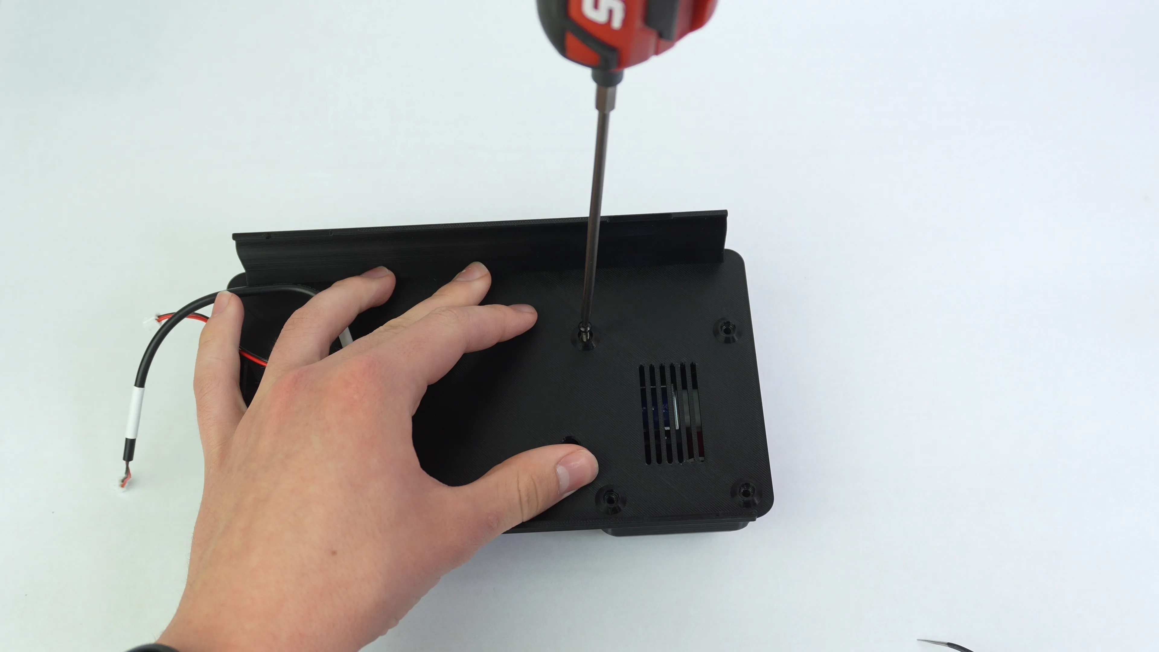
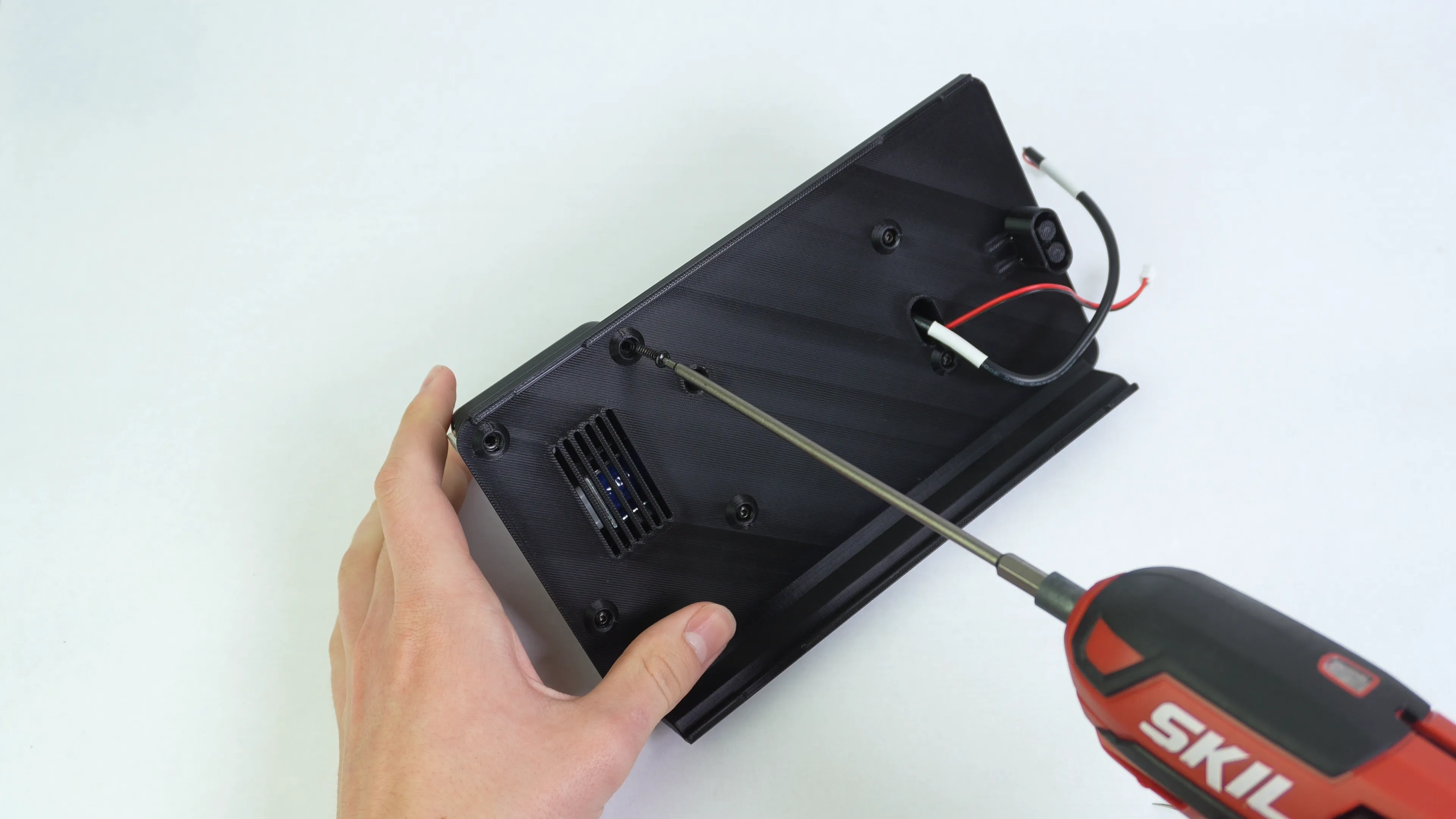
Screw the air assist container to the lid with six M3x12 self tapping screws.
Step 7 of 13
Installing Square Nuts
-
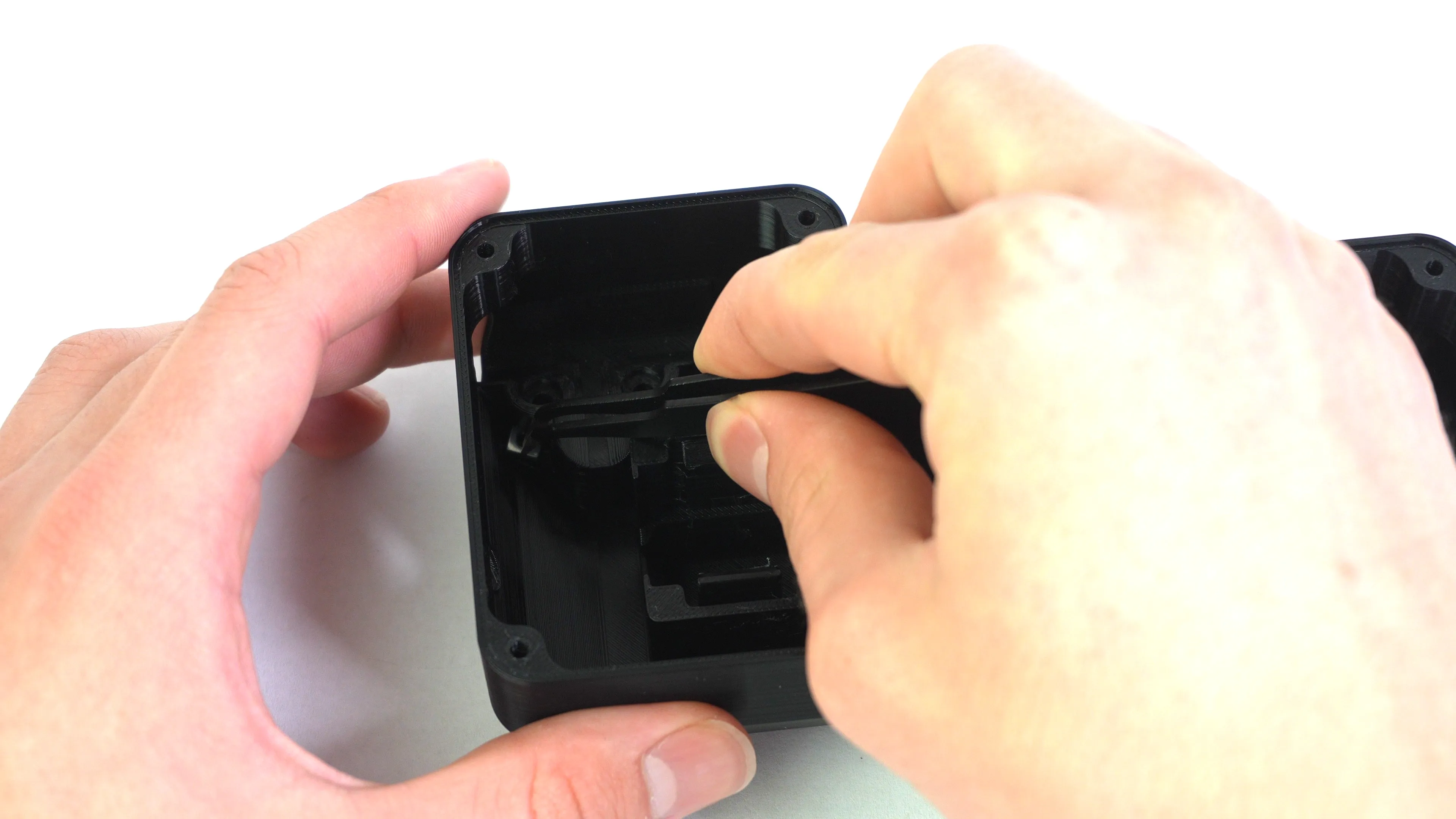
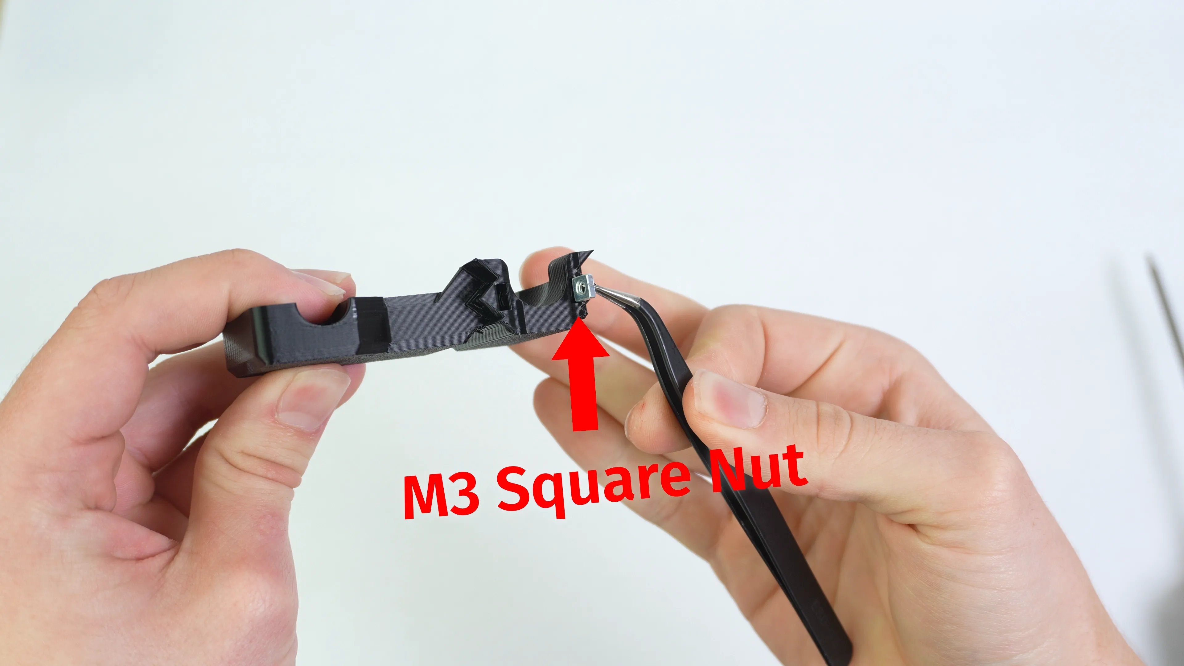
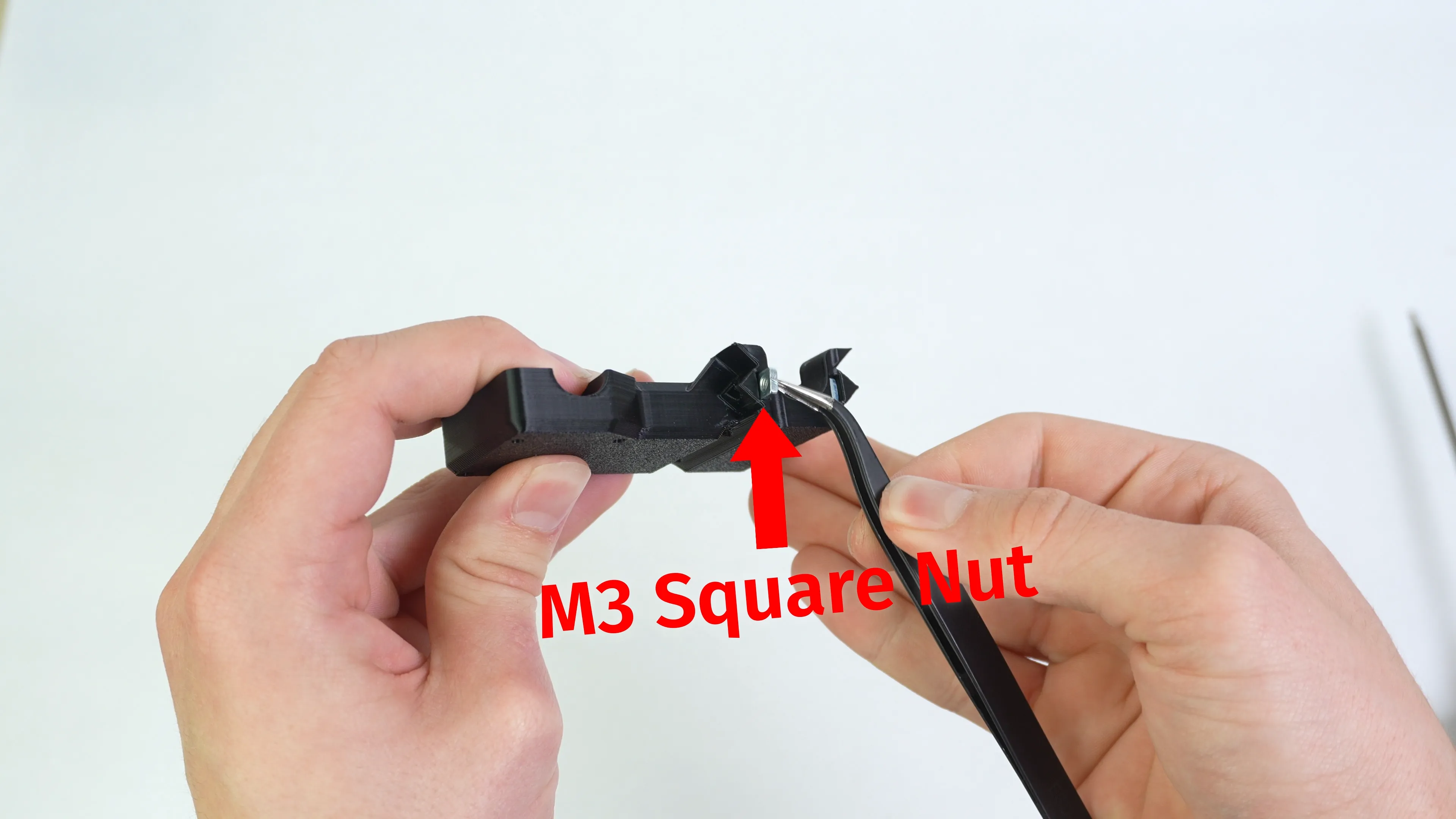
Install two M3 square nuts into the auger stepper mount 3d print. You might have to use the blunt end of a pair of tweezers to push the nuts down.
Step 8 of 13
Ensuring Fitment and Tolerances
-
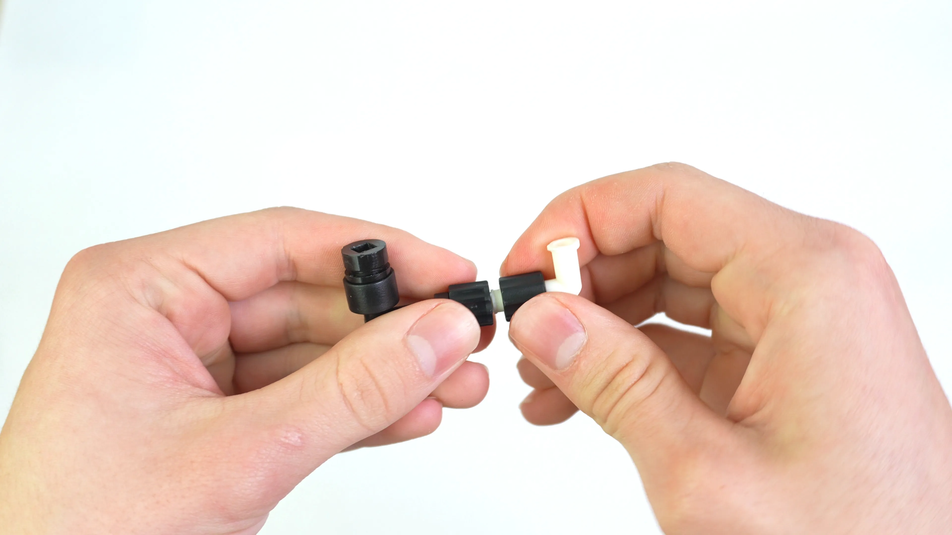
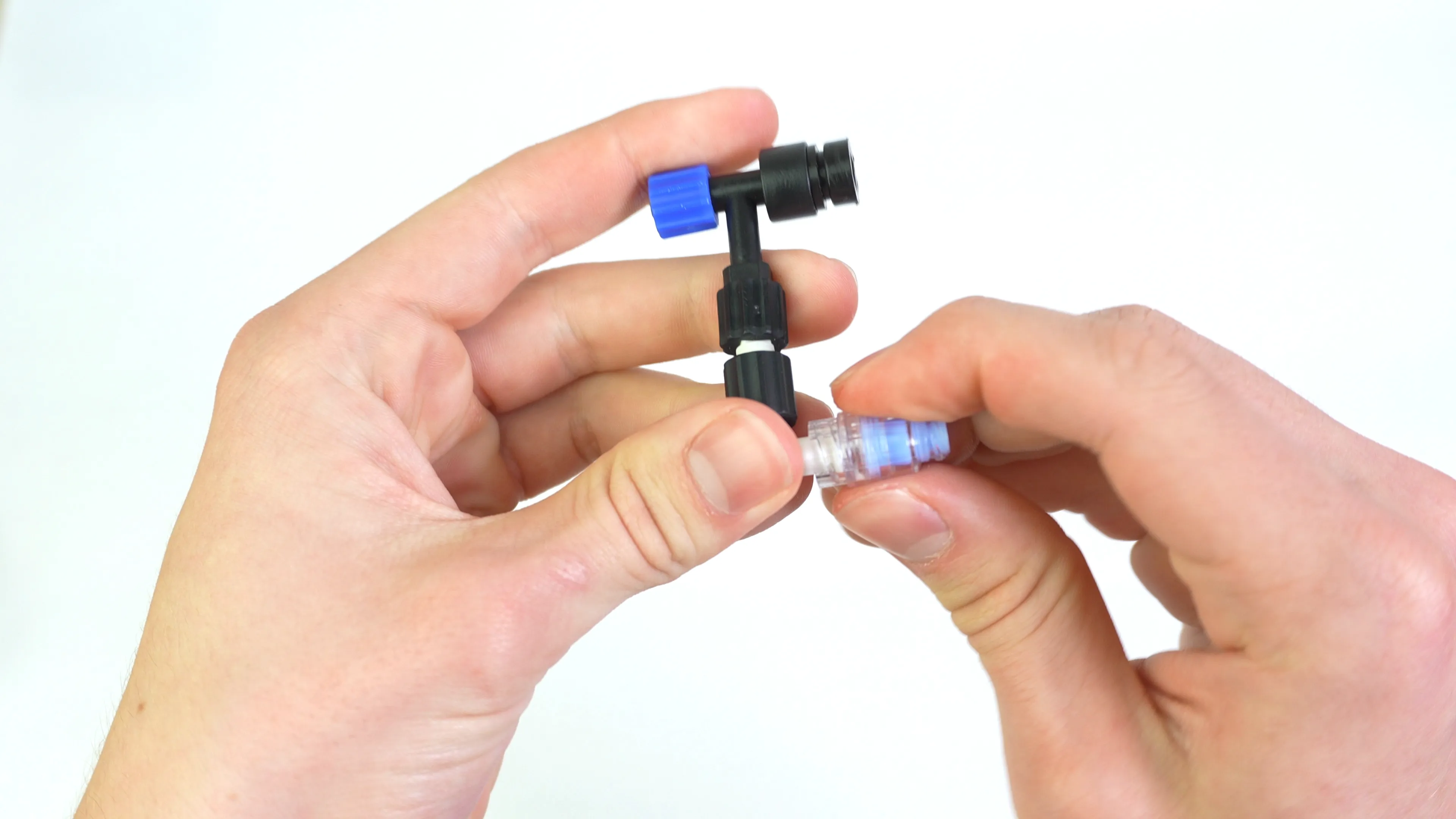
Tighten each luer lock connection on the auger componet to ensure a good seal that will last into the future
-
Install the luer lock extender onto the white right angle luer lock connector of the auger
-
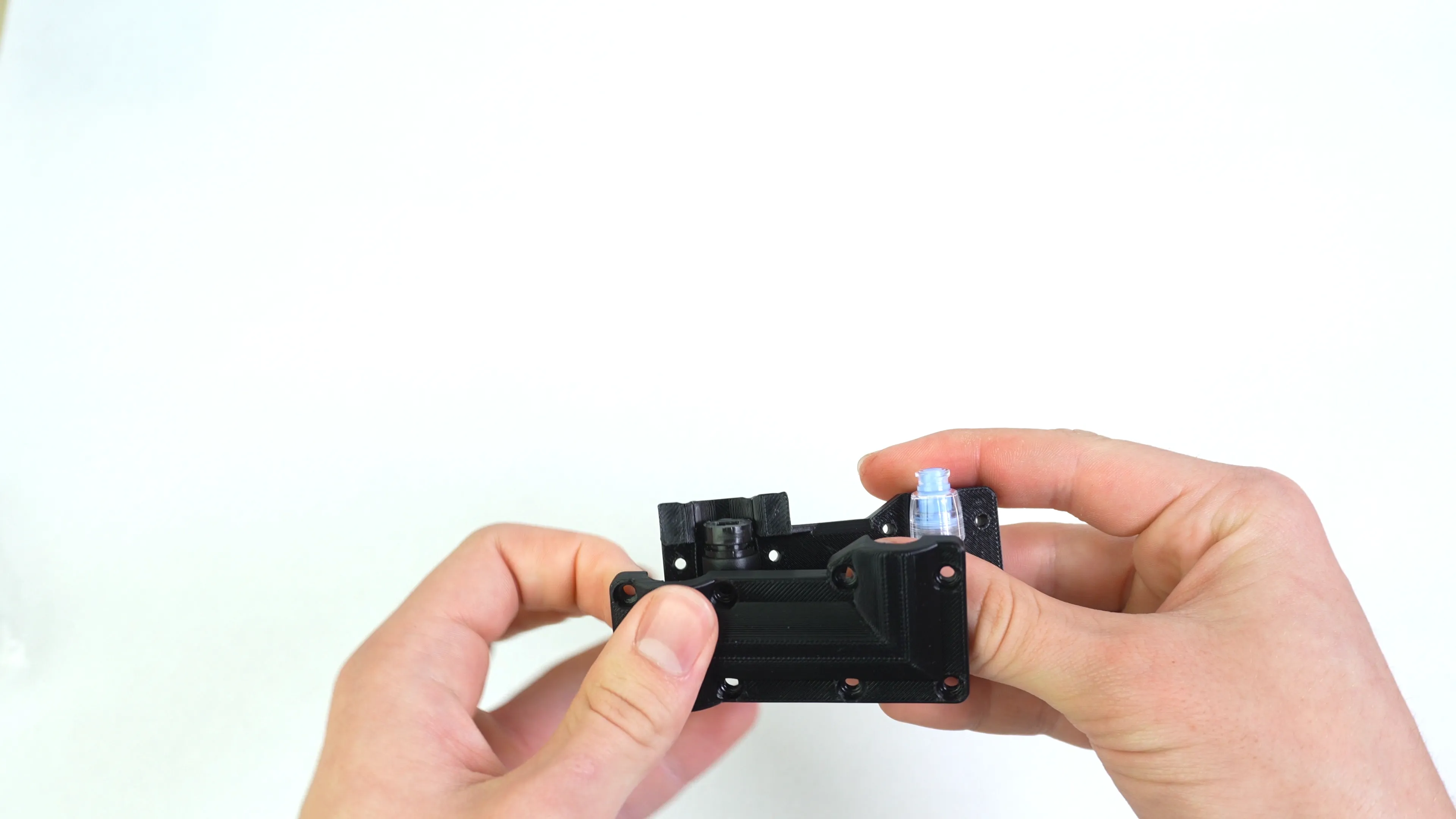
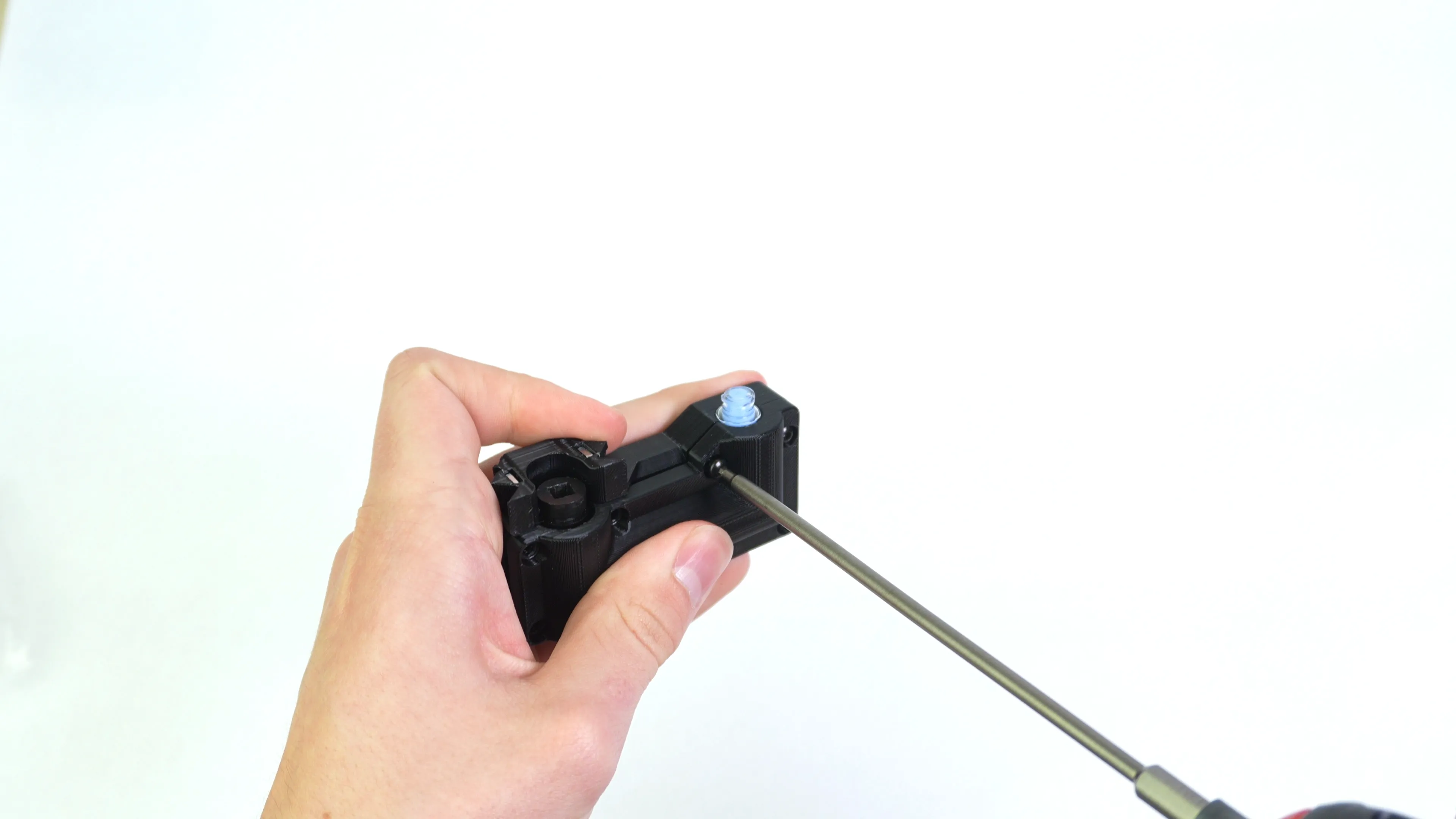
Set the auger in the auger toolhead mount and cover it with the clamp. Ensure that the fitment is within reason.
Step 9 of 13
Screw the Auger Mount Together
-
Start screwing eight M3x12mm self tapping screws in the auger clamp.
-
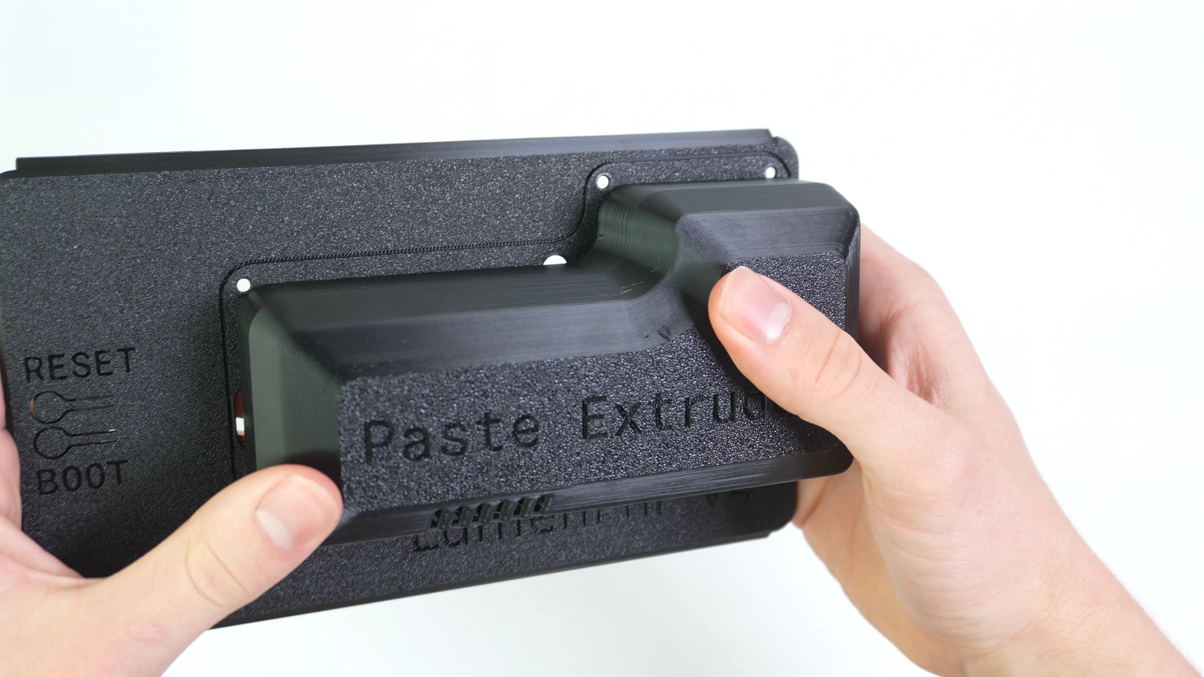
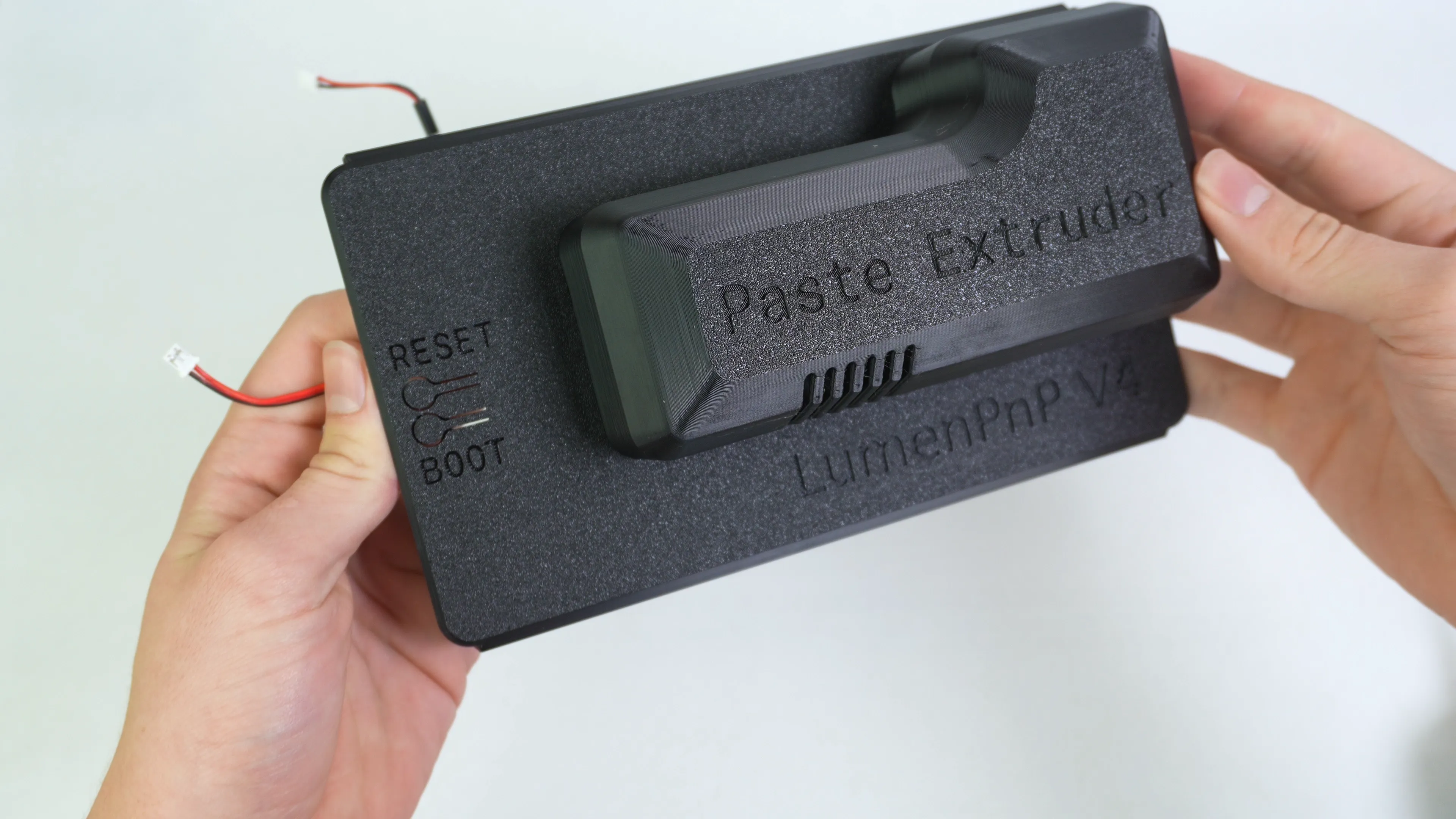
The paste extruder shall match the images below.
Step 10 of 13
Bagging Nozzles
-
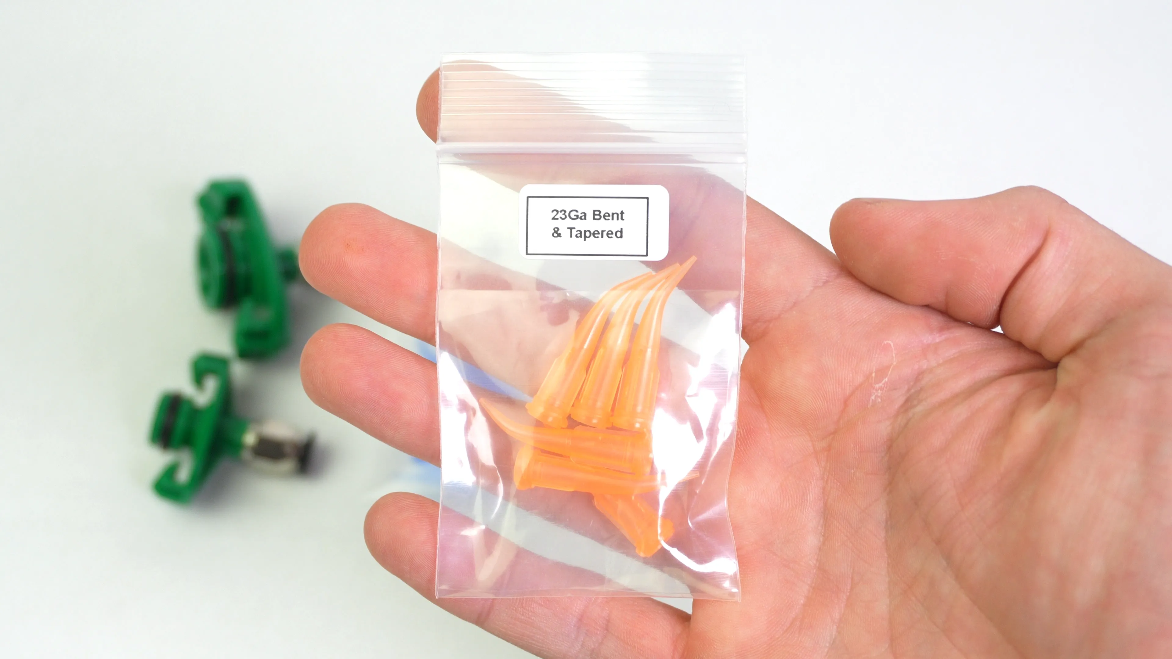
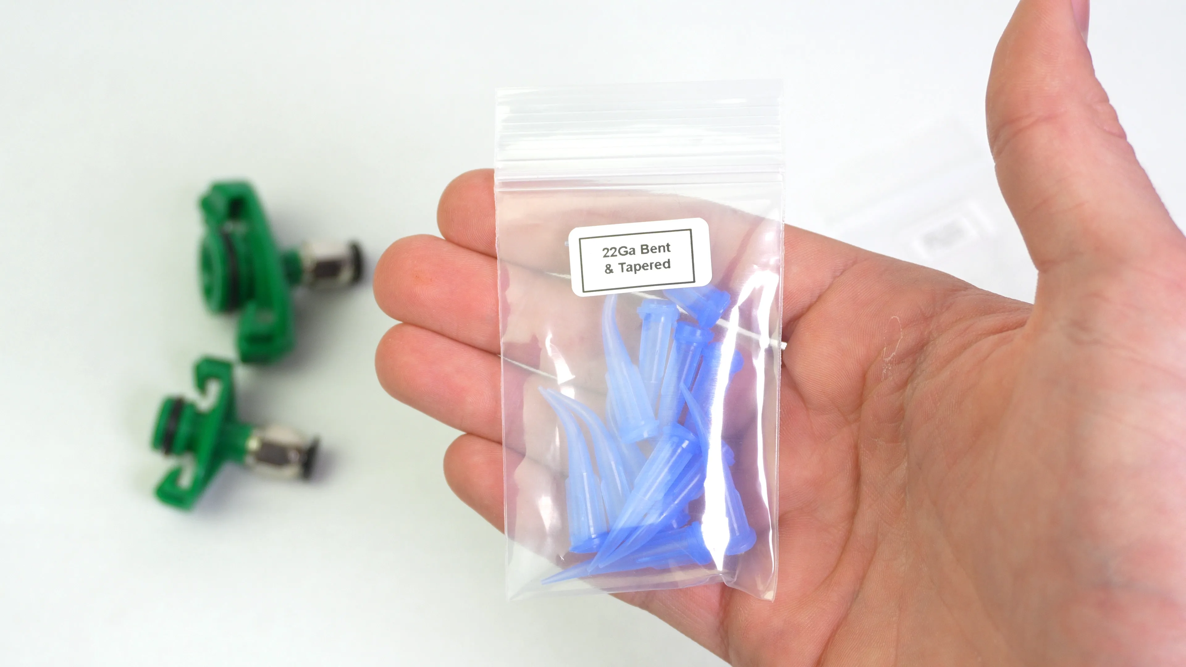
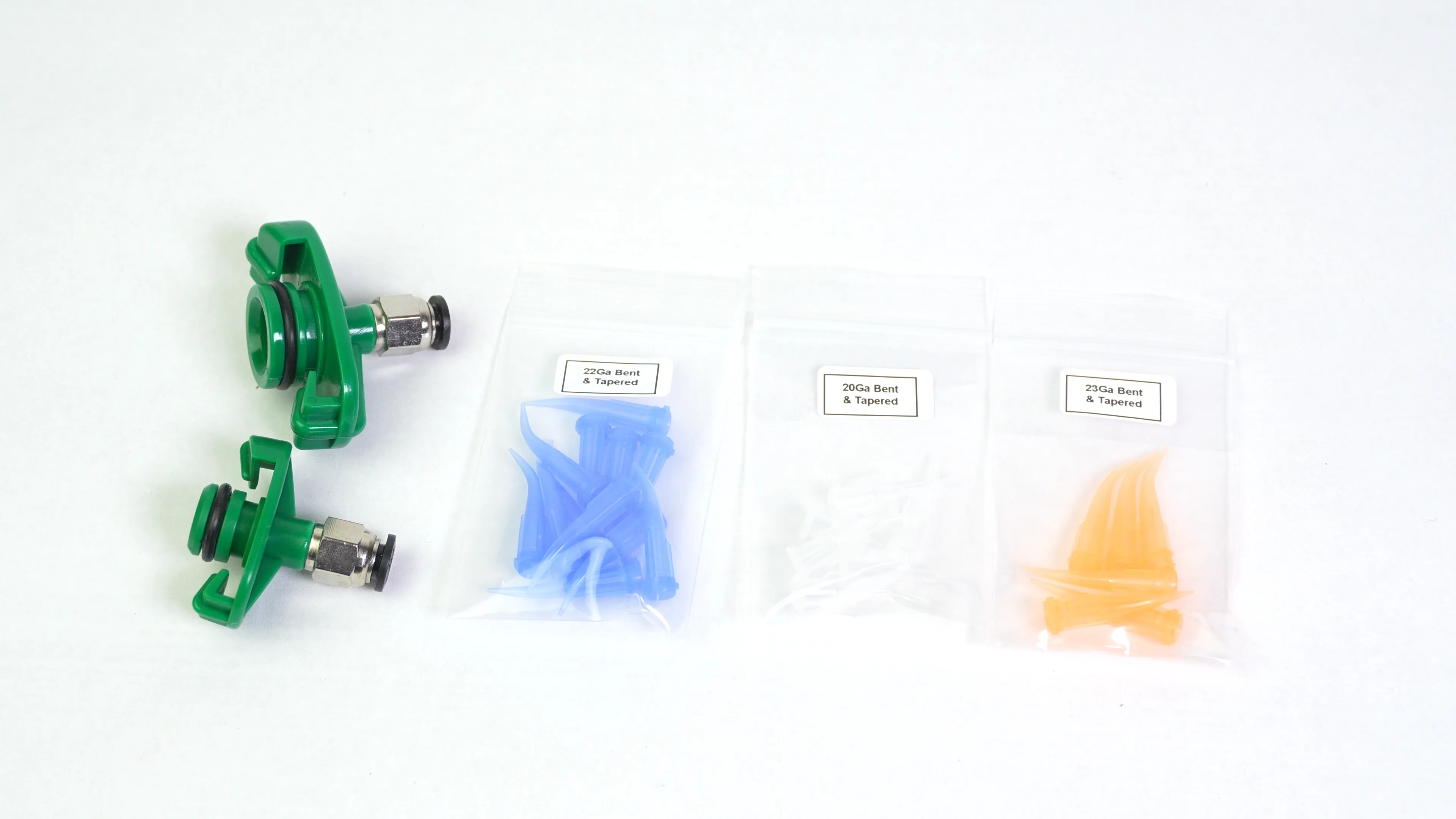
Place six 23Ga bent and tapered nozzles in a small 2x3" clear zip locking bag.
-
Place twelve 22Ga bent and tapered nozzles in a small 2x3" clear zip locking bag.
-
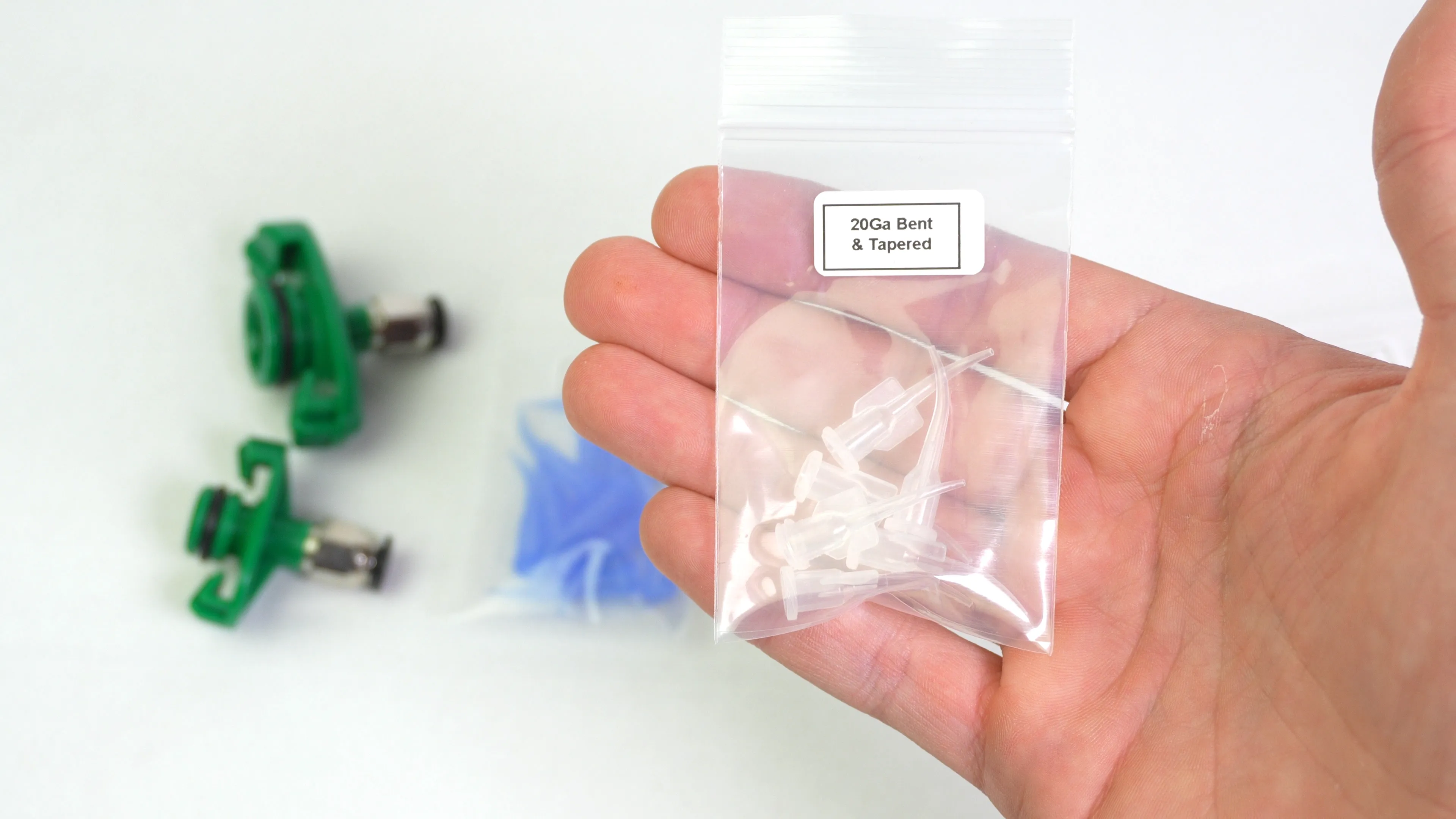
Place six 20Ga bent and tapered nozzle in a small 2x3" clear zip locking bag.
Step 11 of 13
Putting All the Accessories Together
-
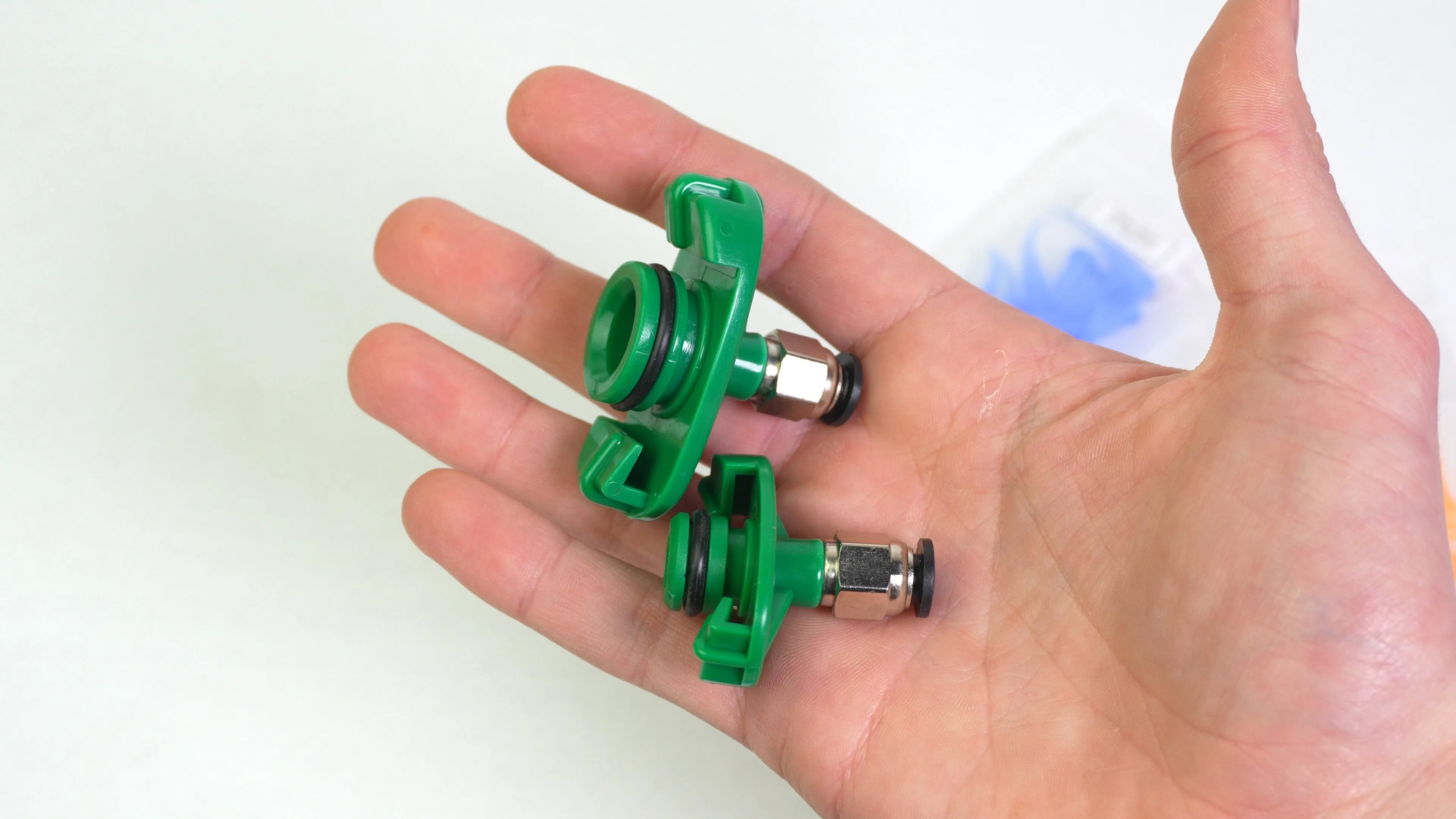
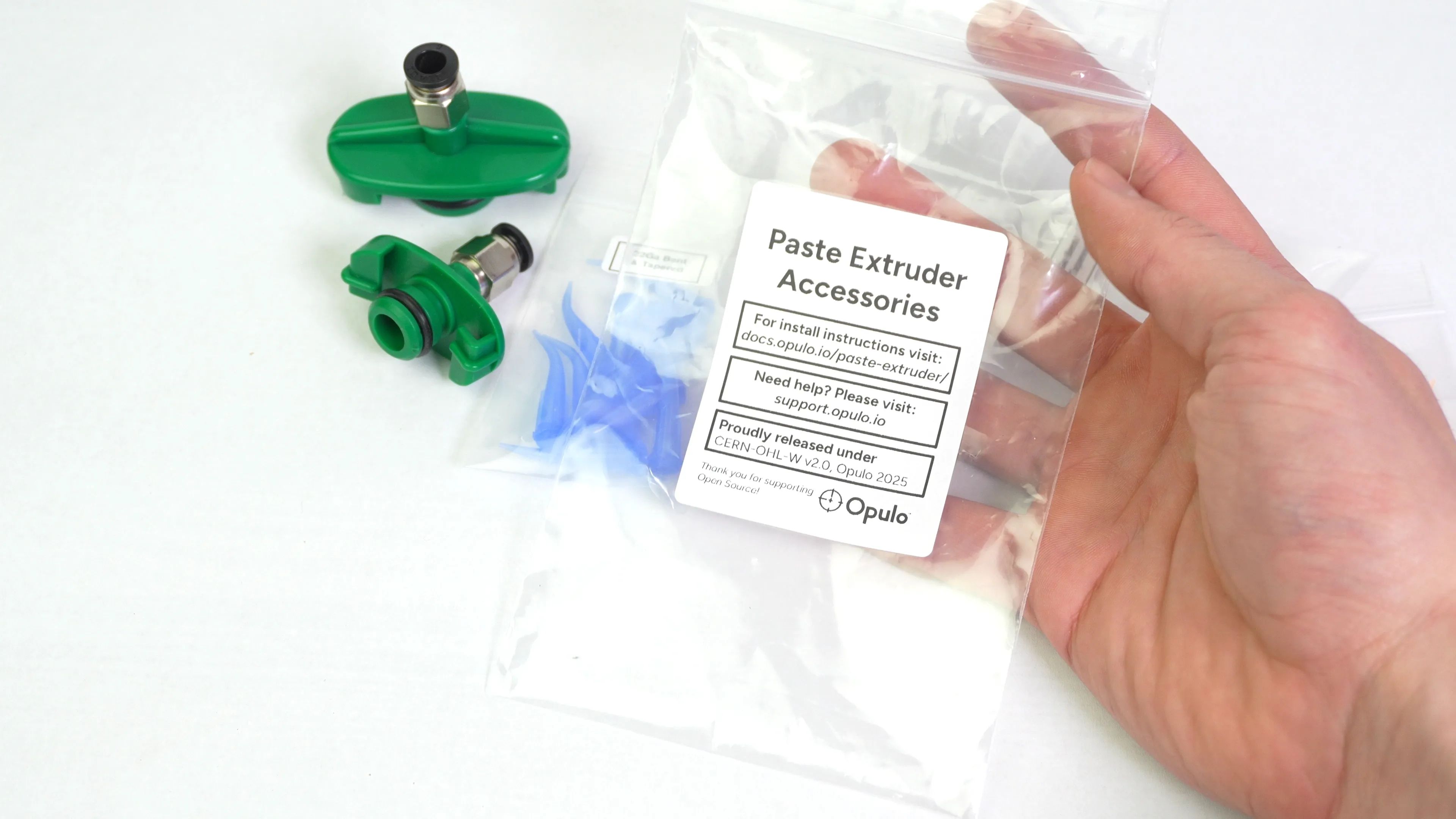
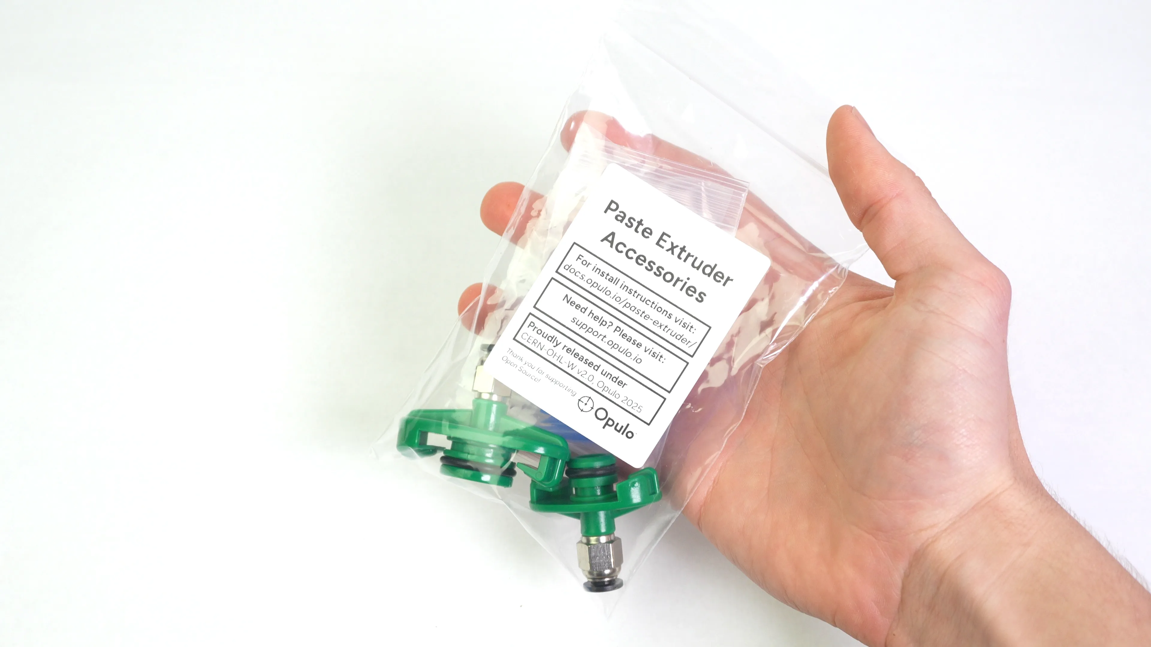
You should now have a 10cc and 30cc air assist cap alongside all of the nozzles.
-
Go ahead and place a Paste Extruder Accessories label found here on a 4x6" zip locking bag.
-
Put all of the accessories into the labeled bag.
Step 12 of 13
Toolhead Bagging
-
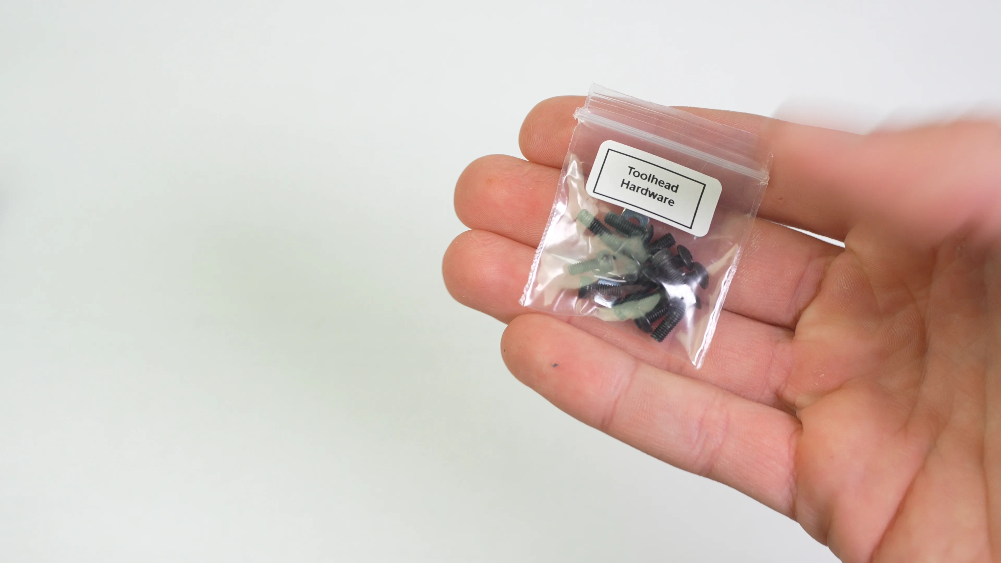
Put toolhead hardware into a 1-1/2x1-1/2" zip locking bag with a label found here. Hardware:
- 3X M3x10mm Button Head Screw
- 5X M3x8mm Button Head Screw
- 5X M2.5x6mm Socket Head Screw
- 2X M3 Square Nut
- 2X 6x5x.42mm Stepper Motor Shim
-
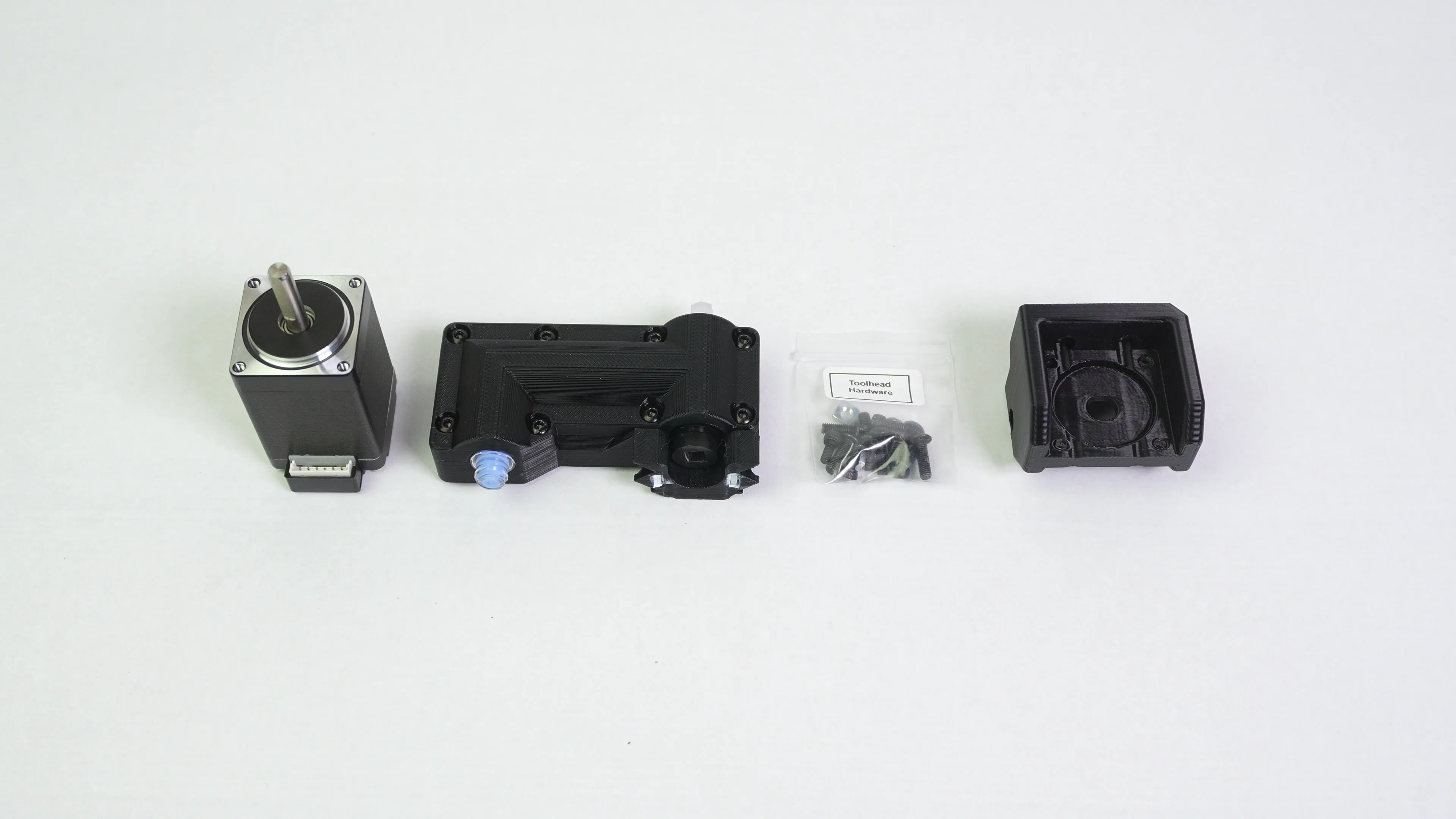
Collect the other hardware:
- 1X Paste Extruder Motor
- 1X Auger Assembly
- 1X Toolhead Mount
- 1X Hardware baggie (we just assembled)
-
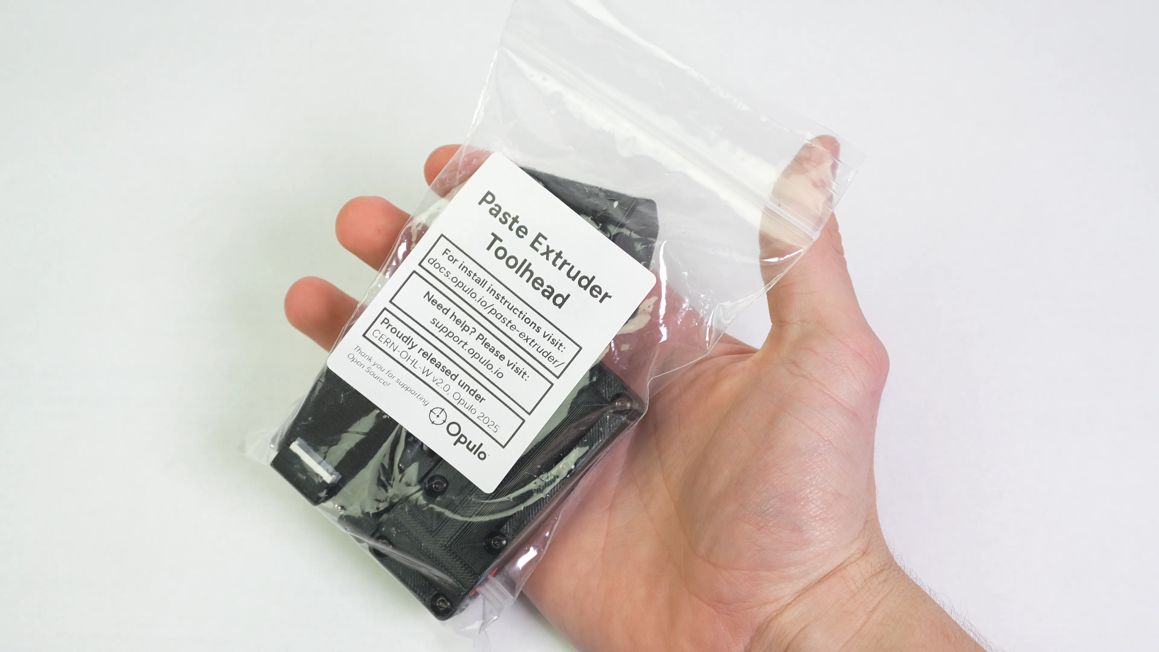
Put everything into a labeled 4x6" zip locking bag, label found here.
Step 13 of 13
Main Packaging
-
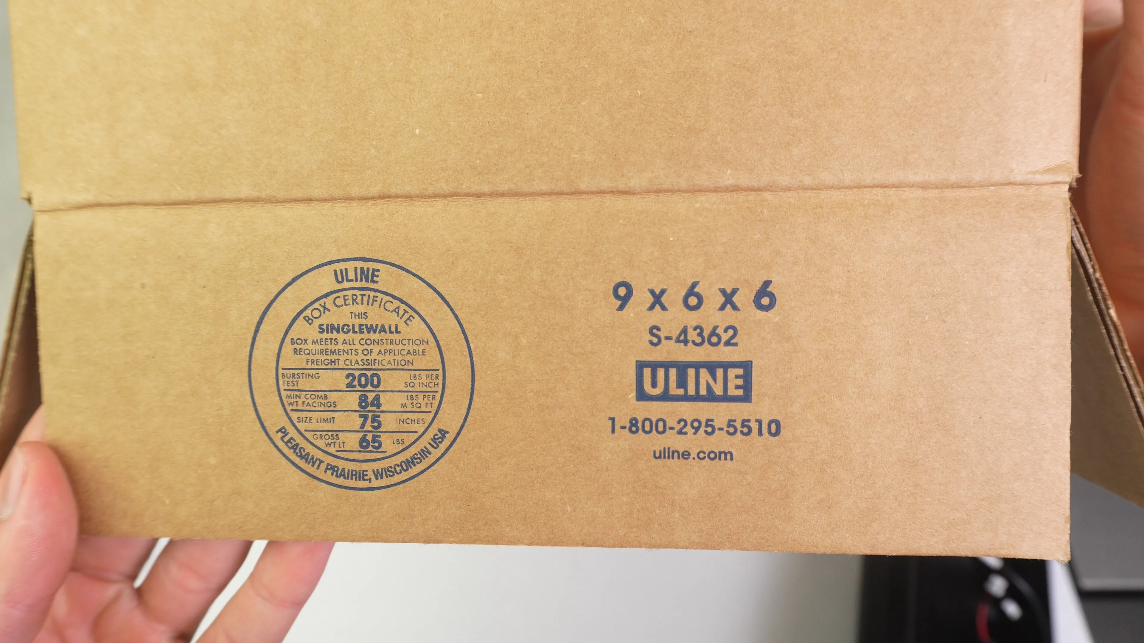
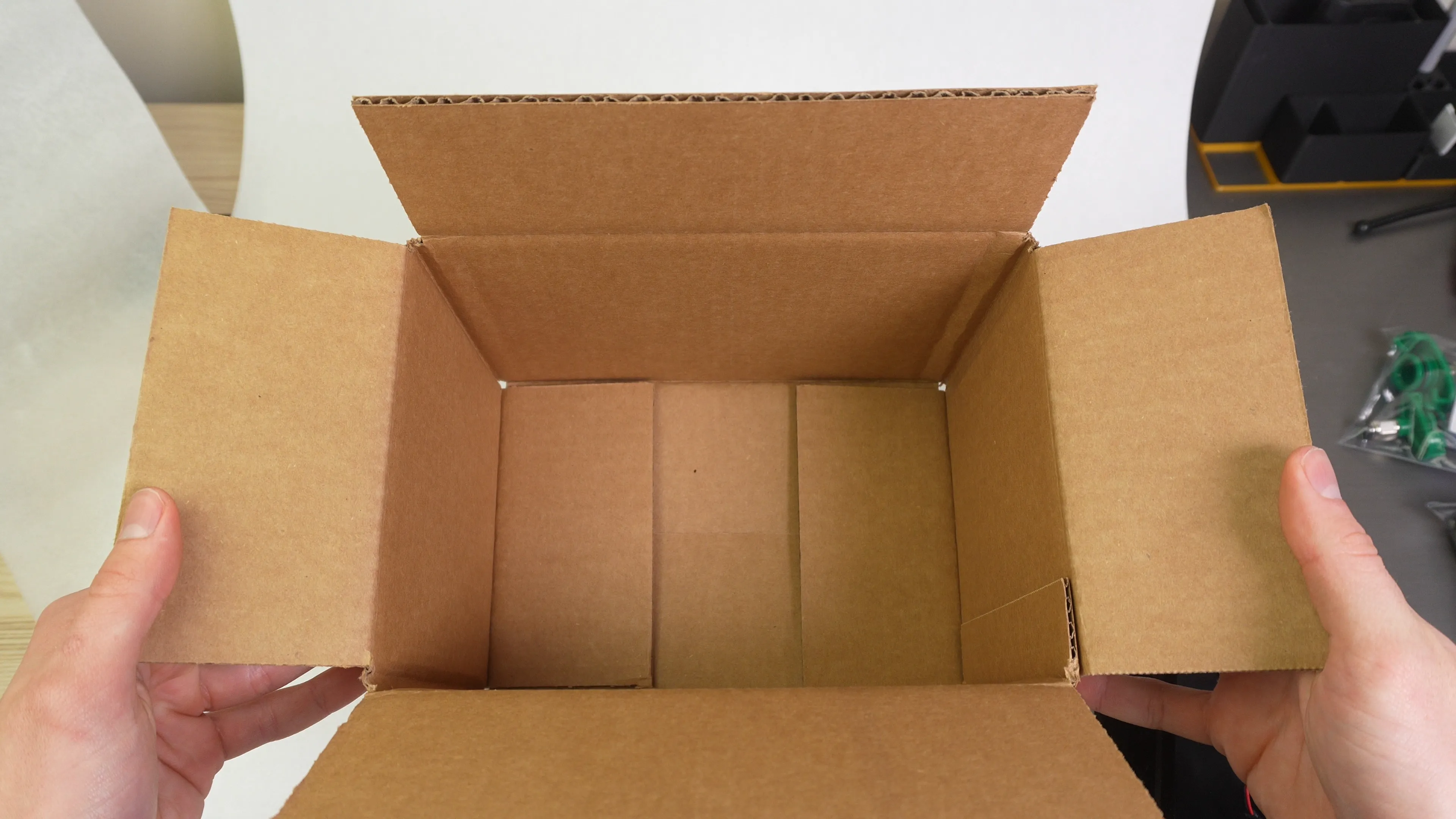
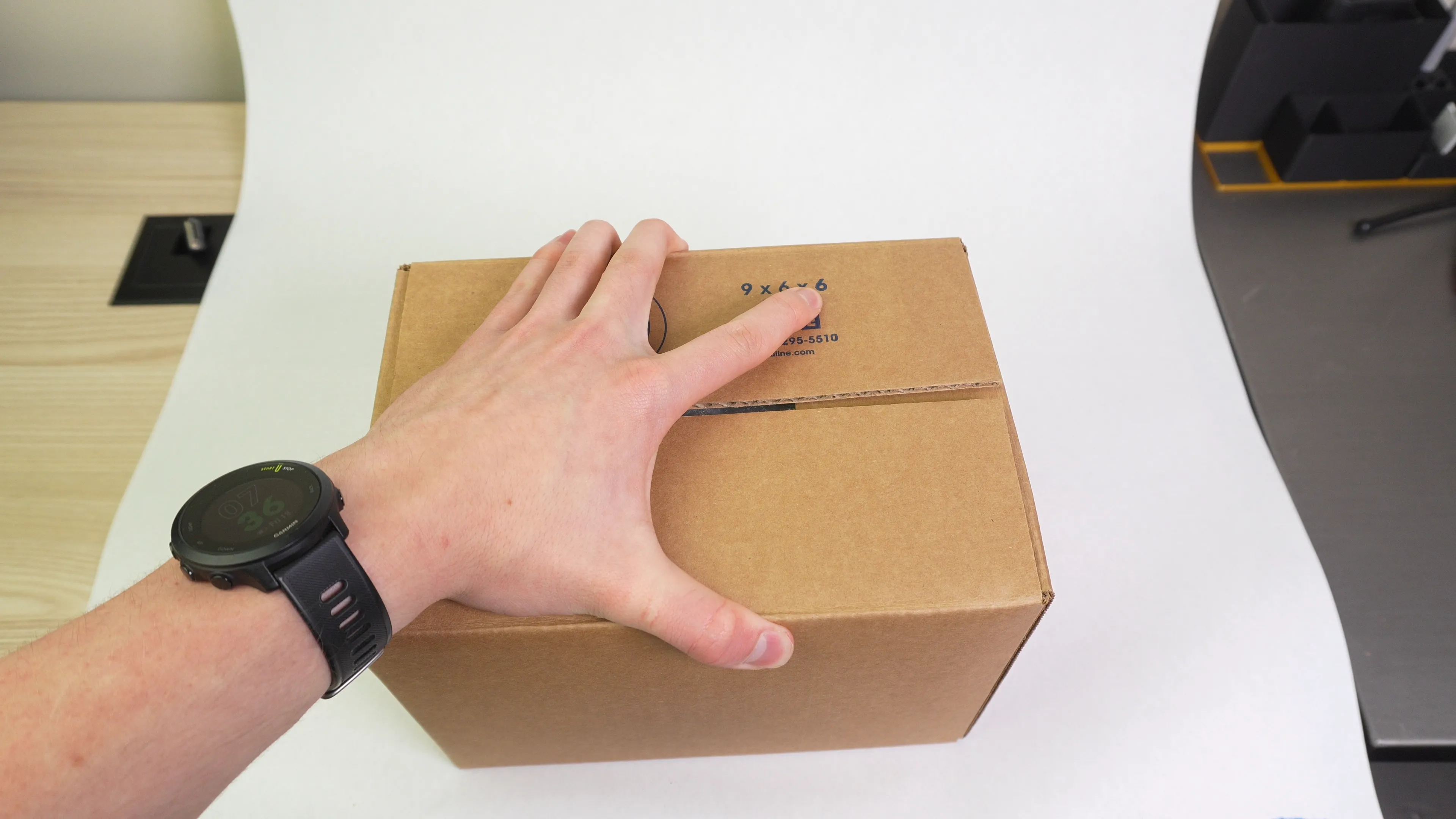
Acquire a 9x6x6" cardboard box
-
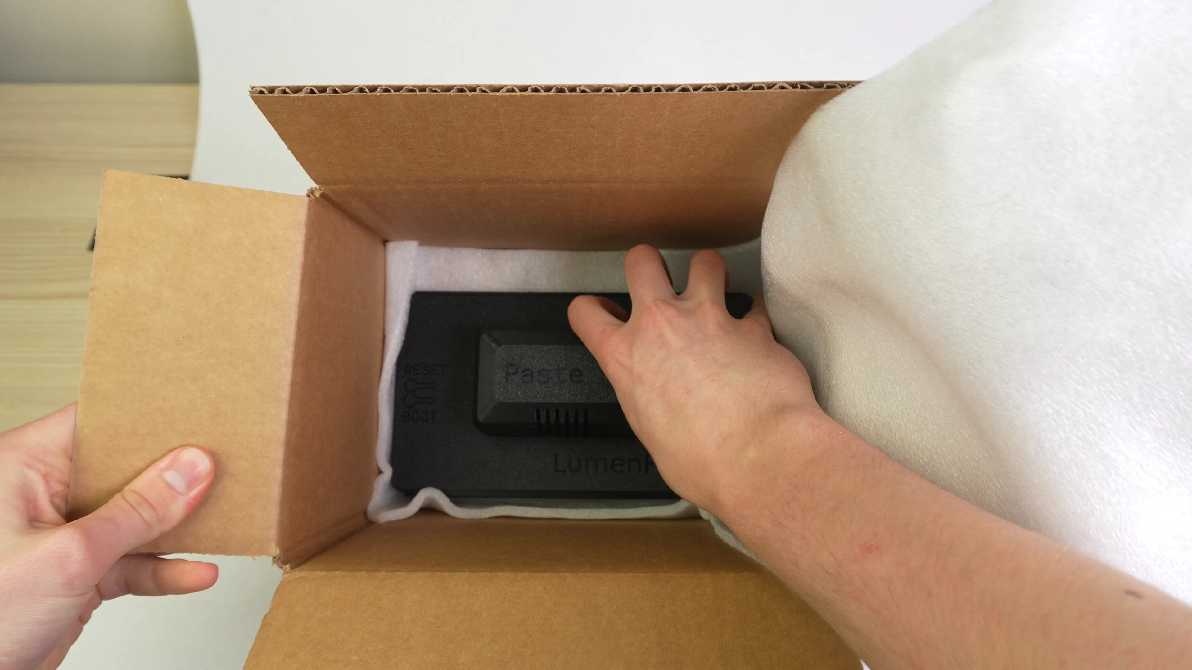
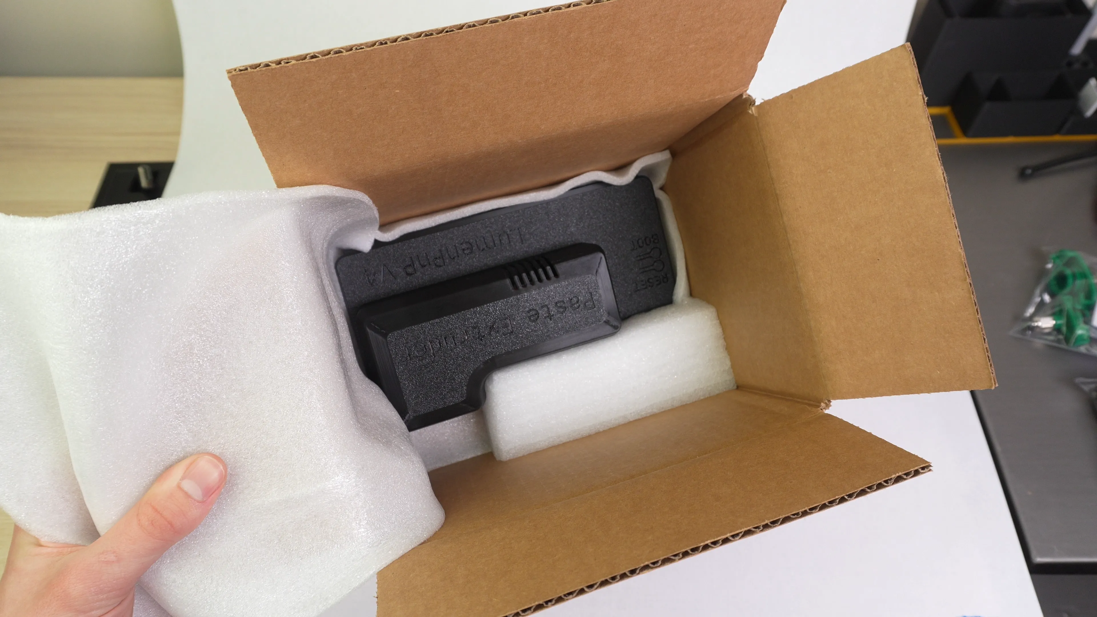
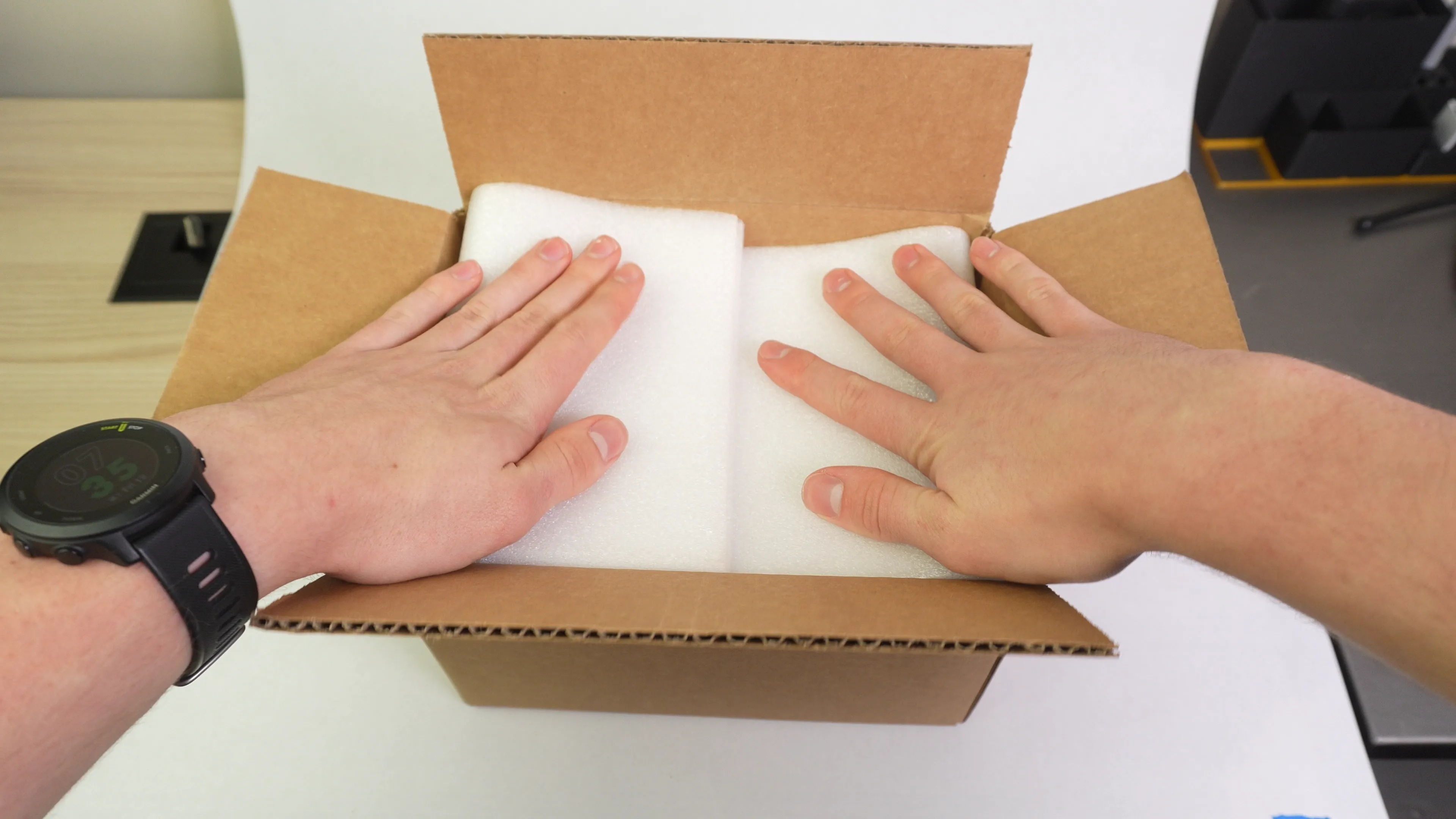
Using a layer of foam place the air assist lid inside of the box and add supplemental foam as well.
-
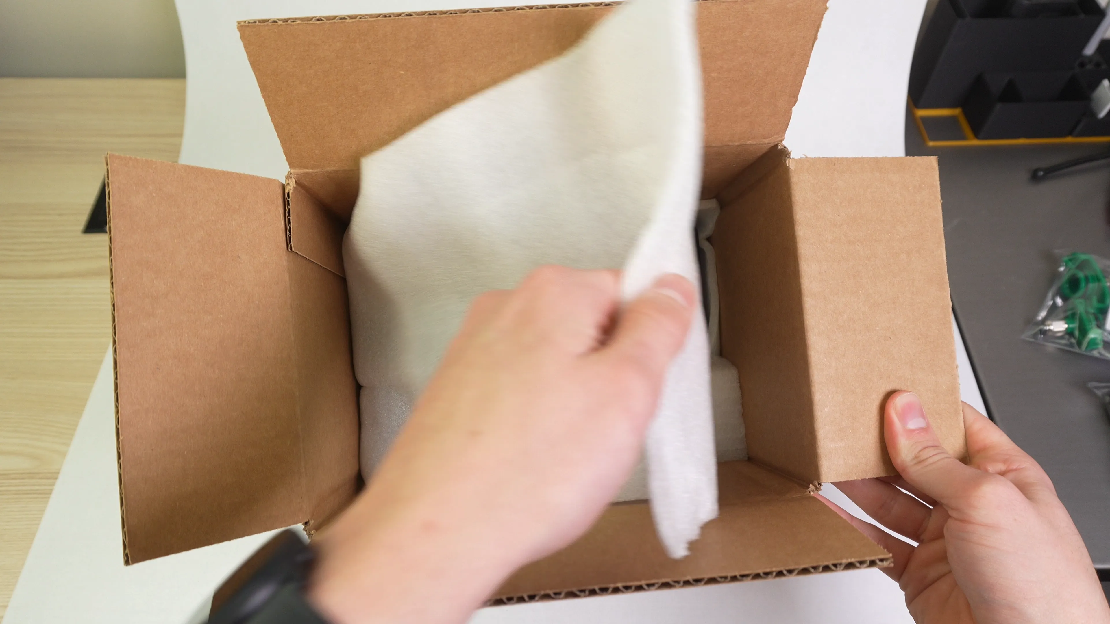
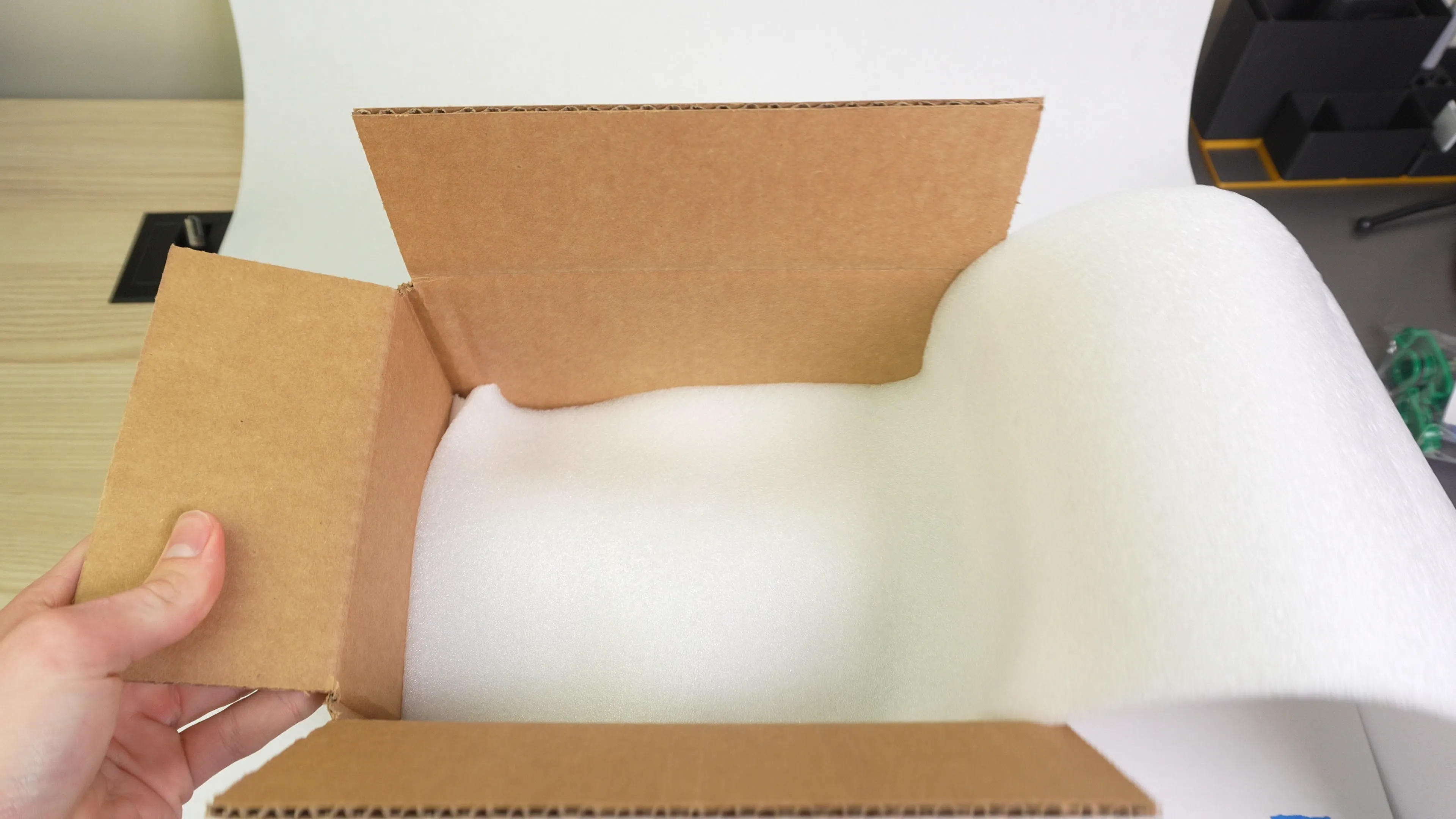
Fold the foam over and add another layer of foam.
-
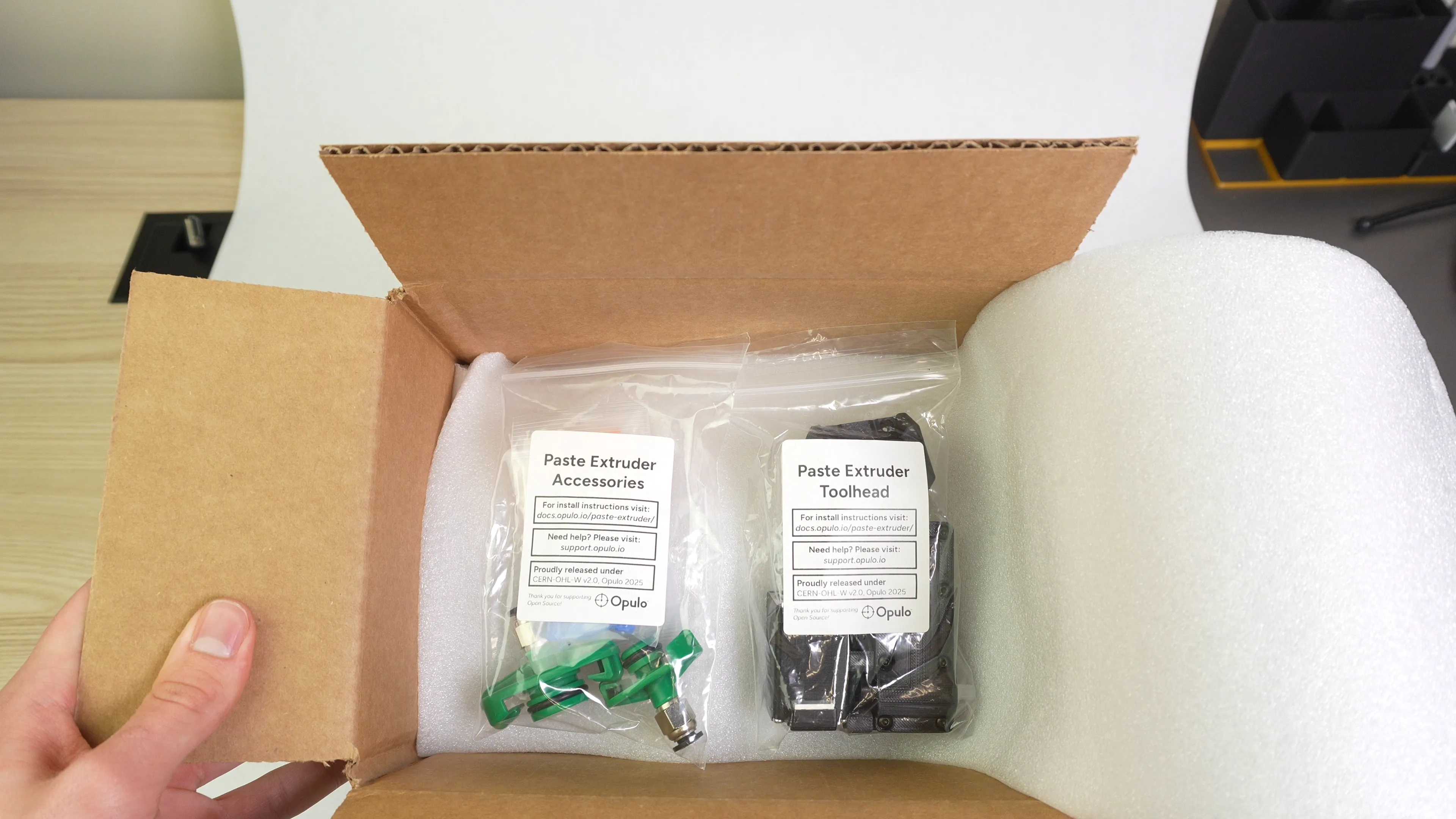
Place the two zip locking bags we assembled earlier on top of the foam. Add more foam and finish packaging the box.