16mm and 24mm Feeder Assembly
Introduction
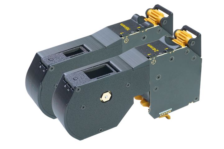
This guide will provide assembly instructions for the 16mm-Feeder and 24mm-Feeder accessories for the LumenPnP. Upon completion, assembly should match the image below:
Tools (Excluding SMT)
- Hex Driver (2mm)
Jigs
- Feeder Loading Station
Important Note
Assemblies for 16mm-Feeder and 24mm-Feeder are the same, however, It is important to note that the feeder-frame, pick-window, and feeder-sticker parts have both 16mm and 24mm varieties. Make sure you print the correct pieces for the accessory you intend to build.
peel-gear Assembly
-
Place
peel-gear-top-2uintopeel-pivot-2u. Be sure to insert the side ofpeel-gear-top-2uwith the divot into the side ofpeel-pivot-2uthat is raised.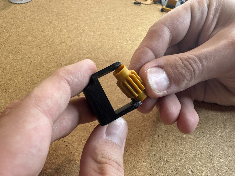
-
Insert
M3x30mm-flat-headthroughpeel-pivot-2uand into the flat side ofpeel-gear-top-2uto secure.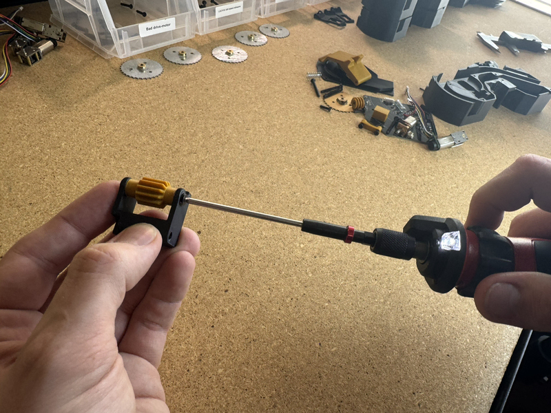
pick-window Assembly
-
Insert
double-torsion-springintopick-window. Pull the wire of the spring over the plastic to secure.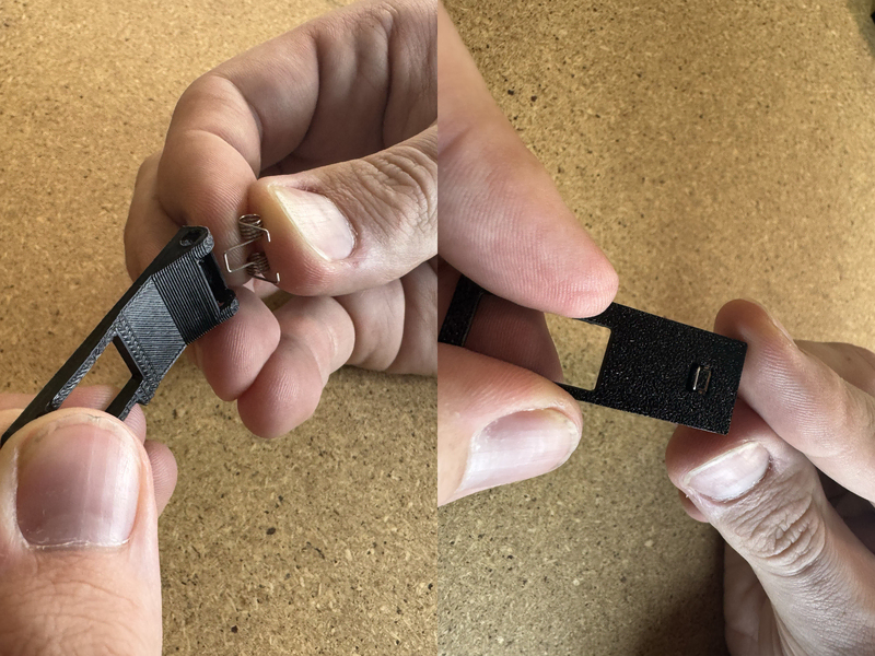
16mm-Feeder Assembly
-
Break support for buttons. Remove and clean support area for
release-lever. -
Insert
n30-motorinto16mm-frame.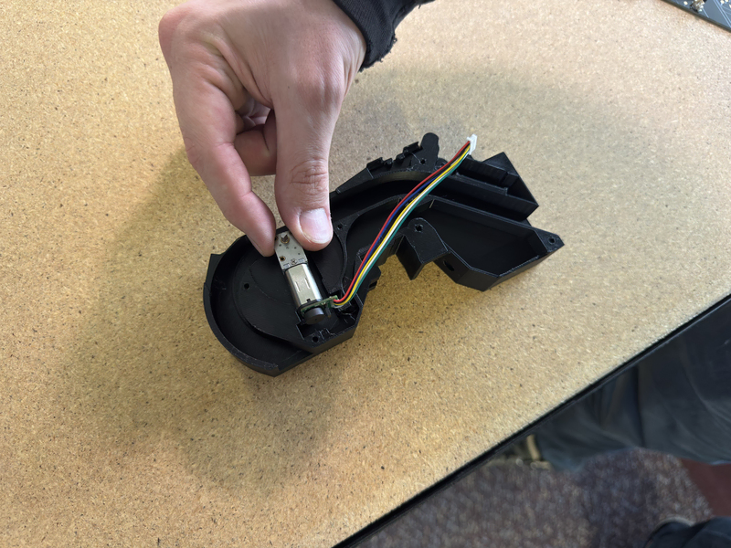
-
Ensure the cables are nestled between the motor and the wall of the print.
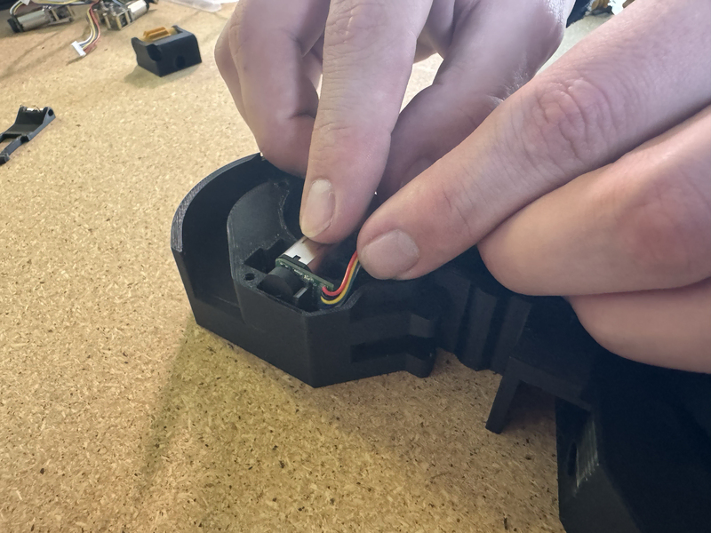
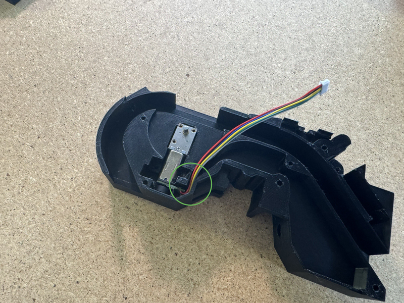
-
Secure
n30-motorwithdrive-motor-bracket. Use 2xm3x12mm-self-tapping-flat-hex-headto keepdrive-motor-bracketin place.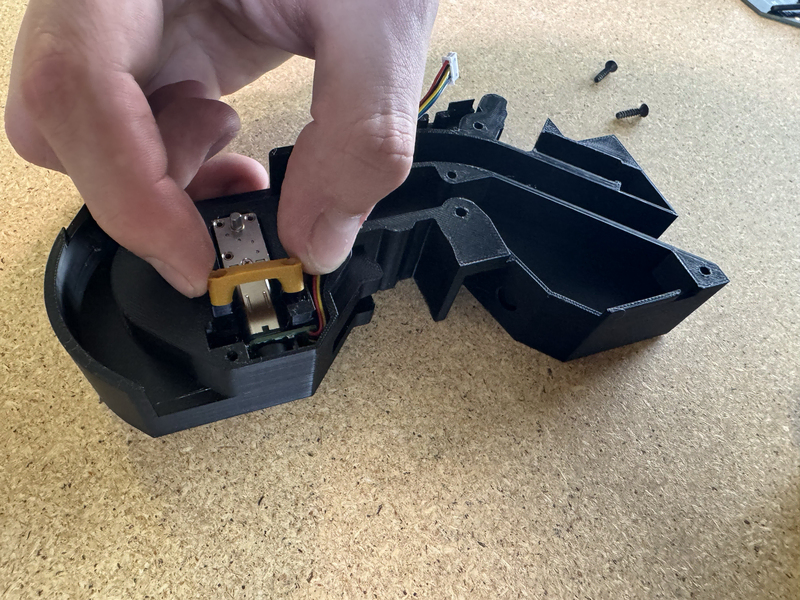
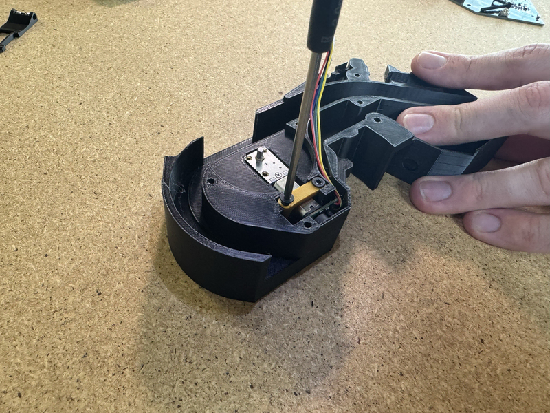
-
Ensure that the 2x
M3x12mm-self-tapping-flat-hex-headare screwed in far enough to sit below the wall of the frame.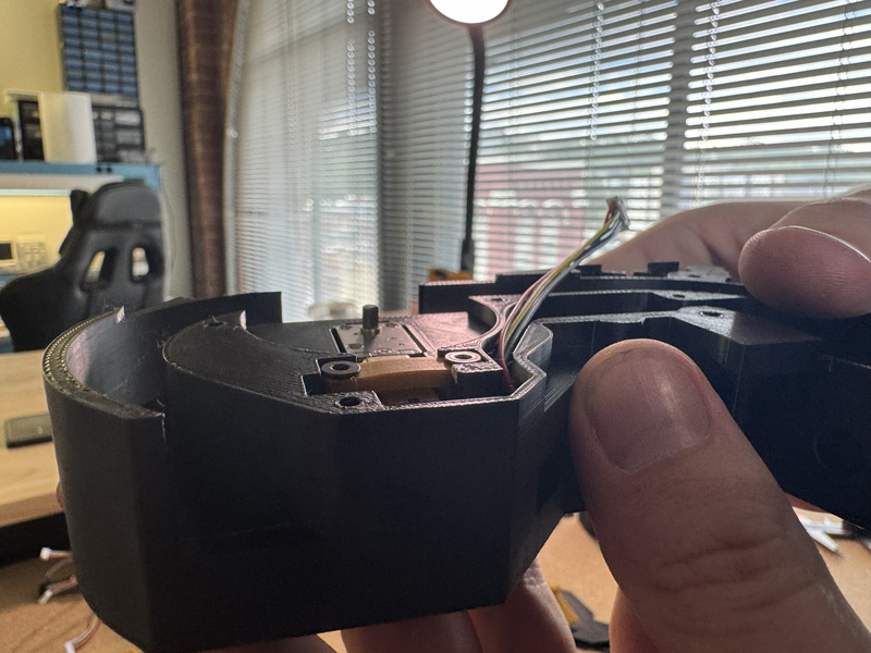
-
Press fit
peel-worm-gearontopeel-motor.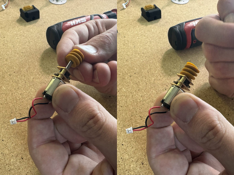
-
Press fit
peel-motorinto16mm-frame.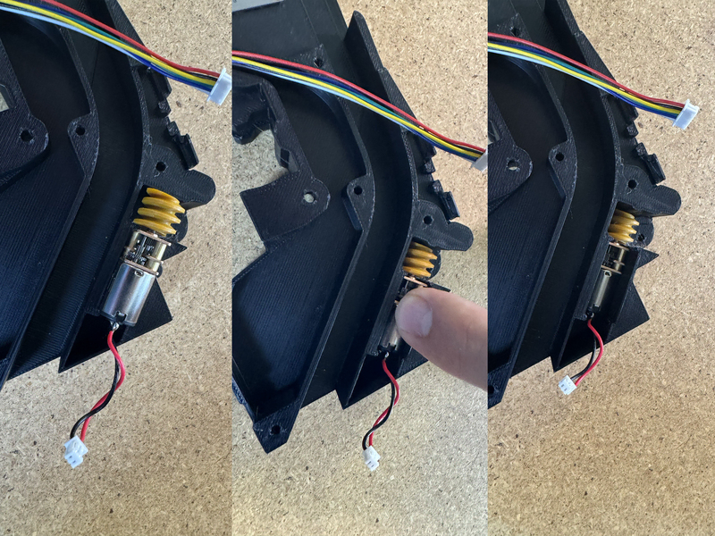
-
Press fit
peel-motor-plugto keeppeel-motorin place.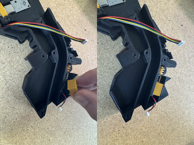
-
Plug the cable from
peel-motorintofeeder-mobo-ott.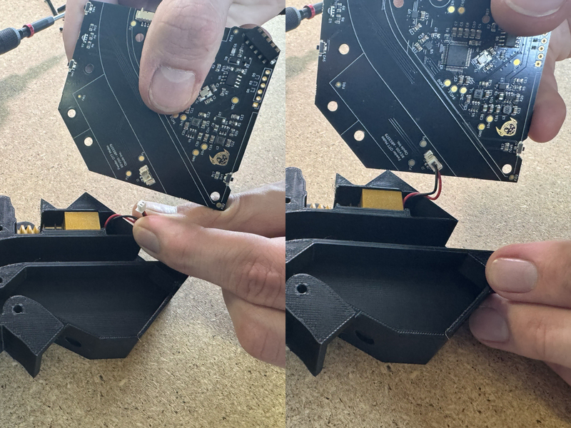
-
Plug the cable from
n30-motorintofeeder-mobo-ott.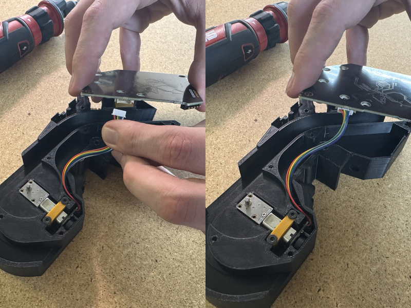
-
Ensure cabling is inside of
16mm-frameandfeeder-mobo-ottis flush against the frame.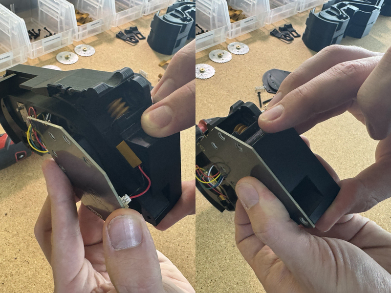
-
Loop cables from
n30-motorto ensure they fit into16mm-framewhile keepingfeeder-mobo-ottflush against the frame.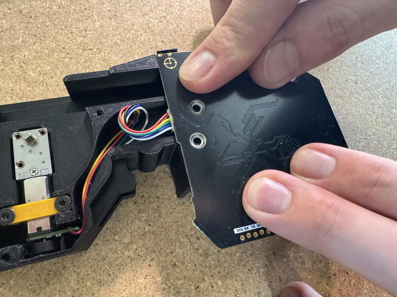
-
Insert 3x
M3x12mm-self-tapping-flat-hex-headand securefeeder-mobo-ott.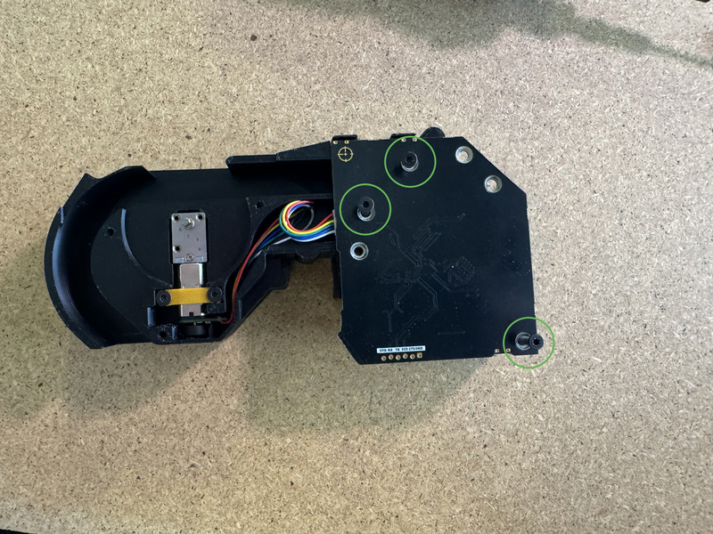
-
Place
peel-gear-bottom-2uinto the frame.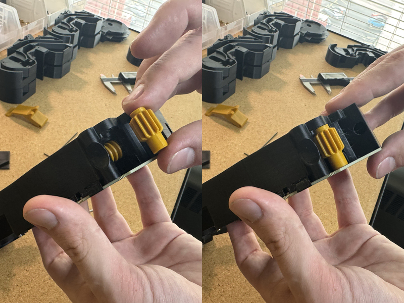
-
Secure
peel-gear-bottom-2uwith 1xM3x30mm-flat-head. Ensure that the screw is not tightened down so much that the gear no longer rotates.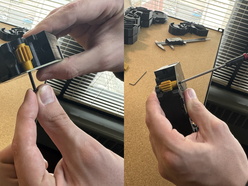
-
Insert
feeder-compression-springto the cutout in the frame.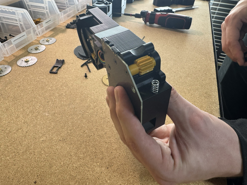
-
Place
peel-gearassembly on top offeeder-compression-springand push down to compress it. Continue holding down the assembly to keep the spring compressed.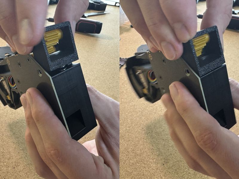
-
While continuing to hold down the assembly to compress the spring, insert 1x
M3x30mm-flat-headto secure the assembly. Avoid overtightening.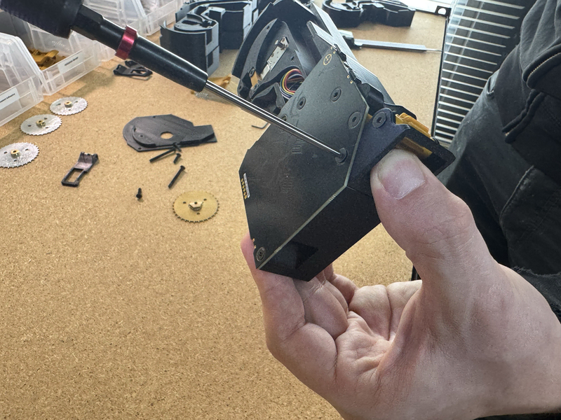
-
Place
feeder-compression-springintorelease-lever. Compress the spring into16mm-framebelow the cutout. Once compressed, slide the spring into the cutout in the frame. You may need to use a small tool to push the spring into place.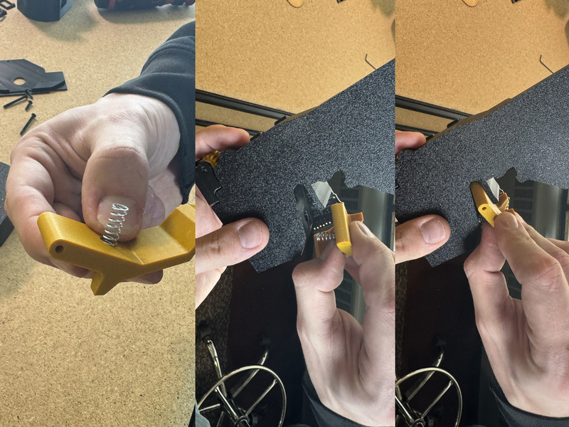
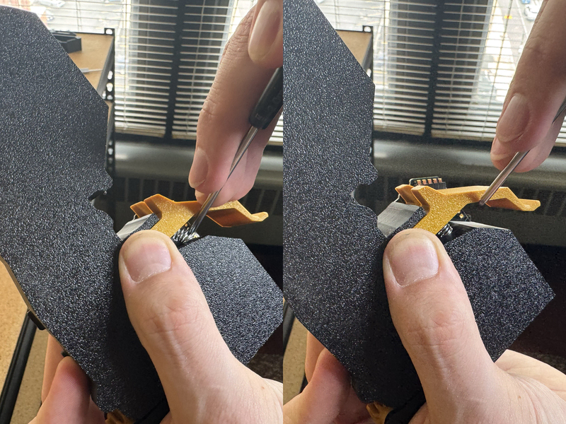
-
Secure
release-leverwithM3x30mm-flat-head. Avoid overtightening.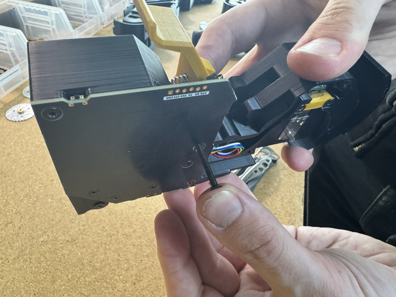
-
Insert
16mm-FeederintoFeeder-Loading-Station. Drive the motor forward until the flat part of the motor is facing up.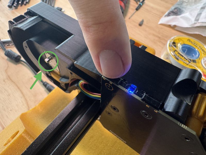
-
Place
drive-wheelonto the motor and secure.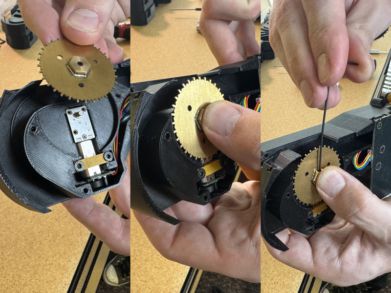
-
Place
drive-motor-coveroverdrive-wheeland secure with 3xM3x12mm-self-tapping-flat-hex-head.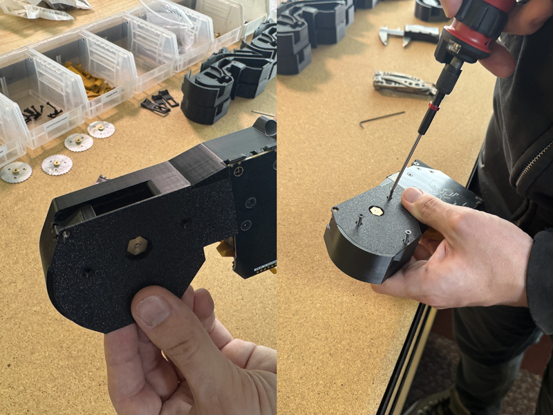
-
Insert
pick-windowassembly by inserting the two legs ofdouble-torsion-springinto the cutout of16mm-frame. Hold down while securing withM3x30mm-flat-head. Avoid overtightening.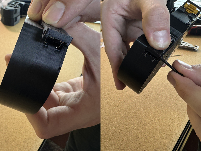
-
Apply
16mm-feeder-sticker.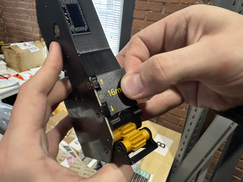
Success
You have successfully assembled a 16mm Feeder.