Feeder Loading Station
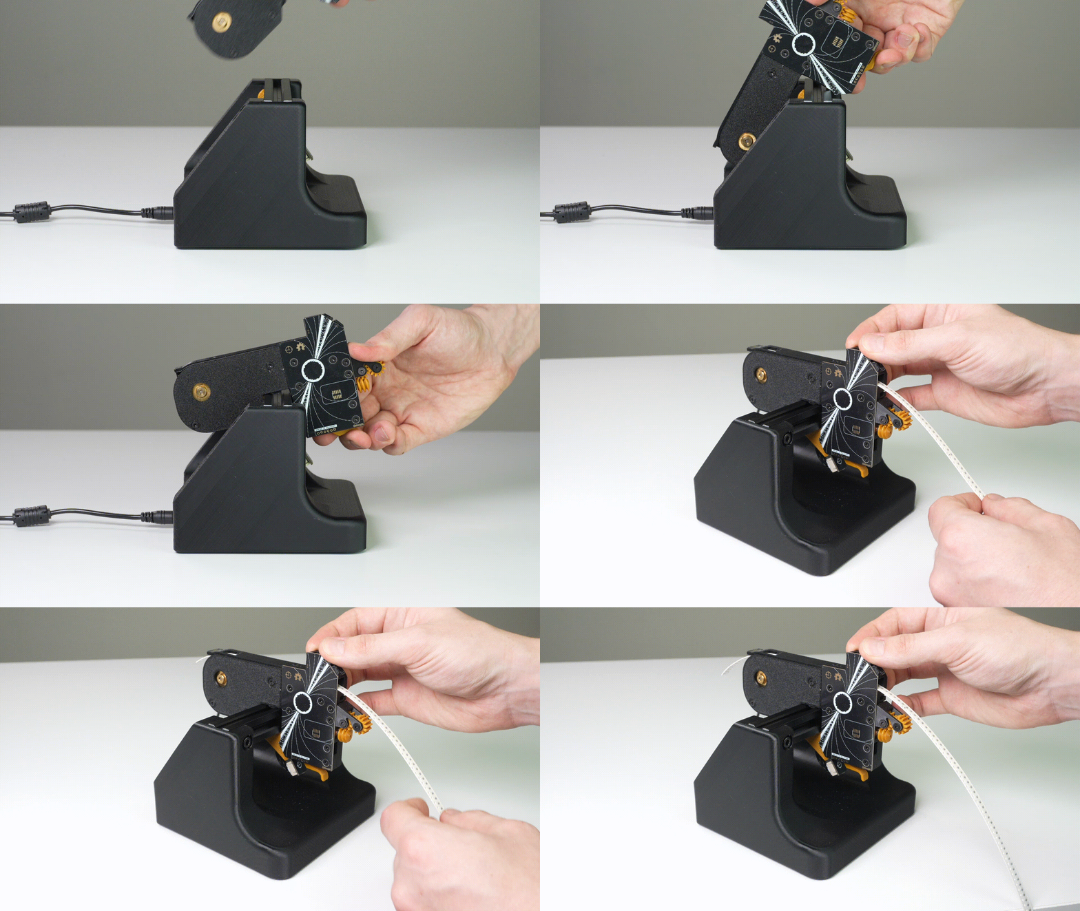
Required Parts
-
3D Prints:
fls-basefls-coverfls-slotextrusion-cable-clip
-
PCBs:
power-breakoutfeeder-slot
-
Fasteners:
M3x8mm-self-tapping-flat-hex-headM5-tslot-nutM5x10mm-socket-head
-
Other:
short-photon-harness- cable harnessvslot-extrusion-20mm-x-20mm-x-140mm- extrusionrubber-foot- rubber feet for stability
-
Jigs:
feeder-blade-jigslot-centering-jig
Assembly Instructions
-
Use
m3x8mm-self-tapping-flat-hex-headto securefeeder-slotPCB tofls-slotprint. Usefeeder-blade-jigto make alignment easier when securing multiplefeeder-slotPCBs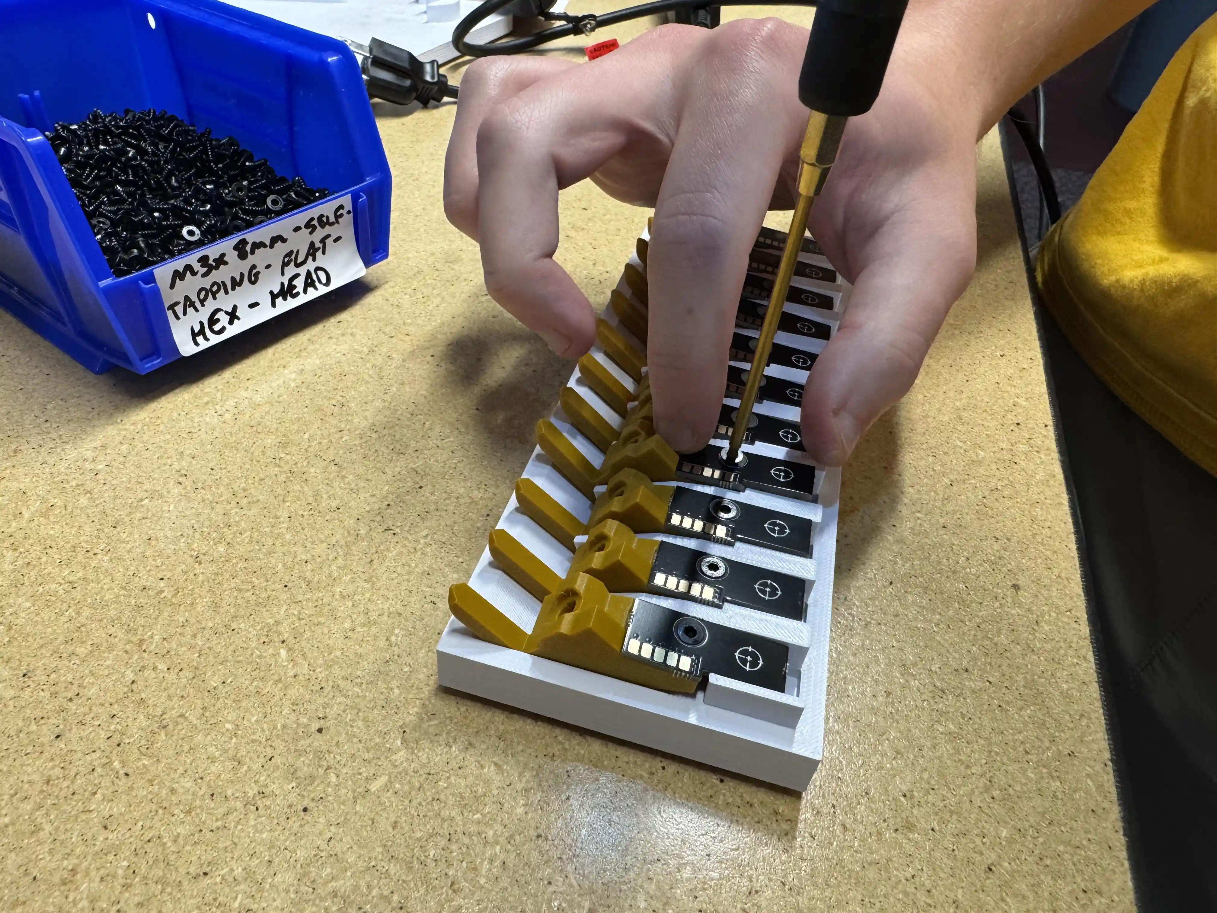
-
Insert
m5x10mm-socket-headinto the large opening at the bottom of thefls-slotprint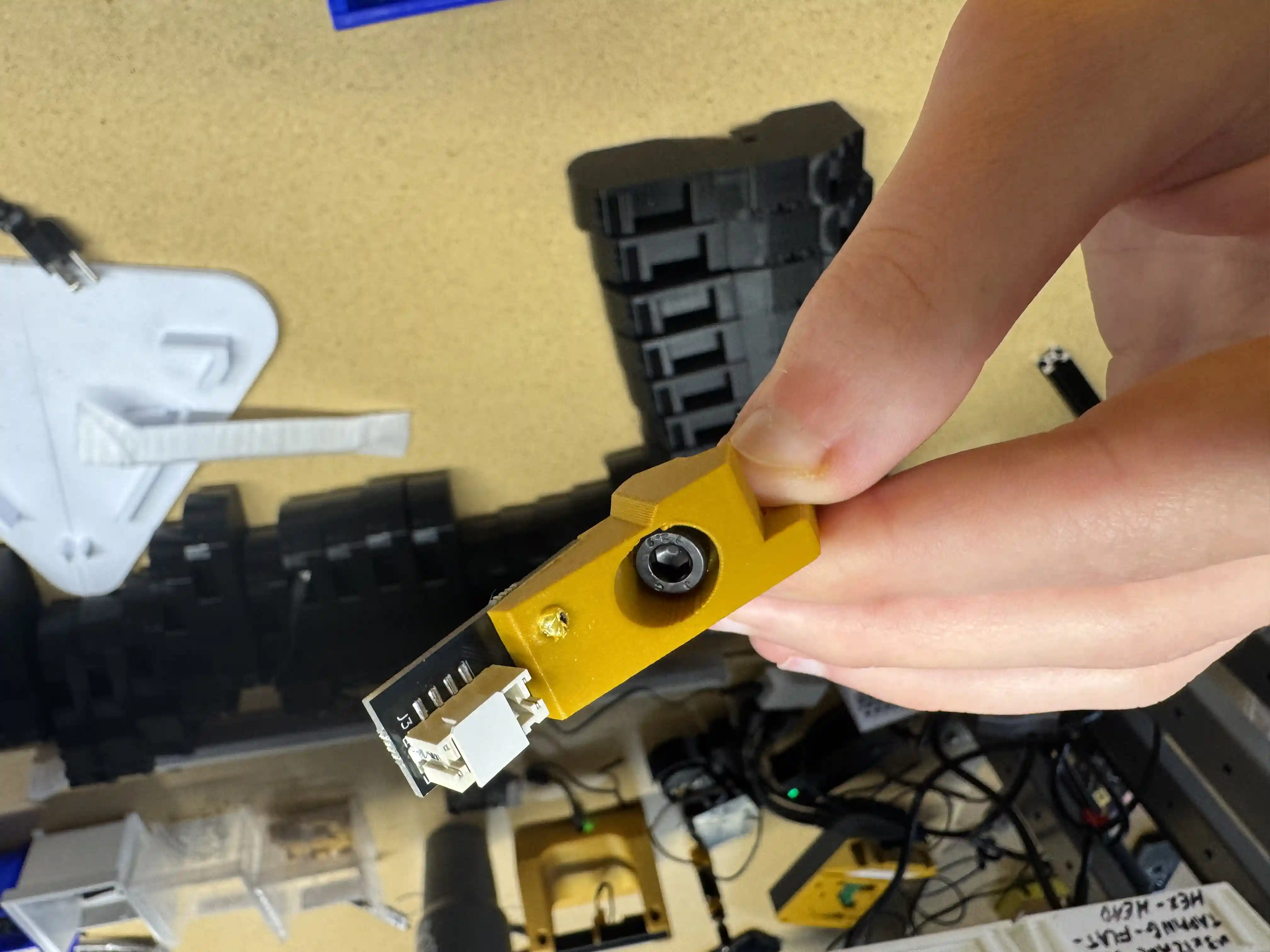
-
Thread on
m5-tslot-nutontom5x10mm-socket-head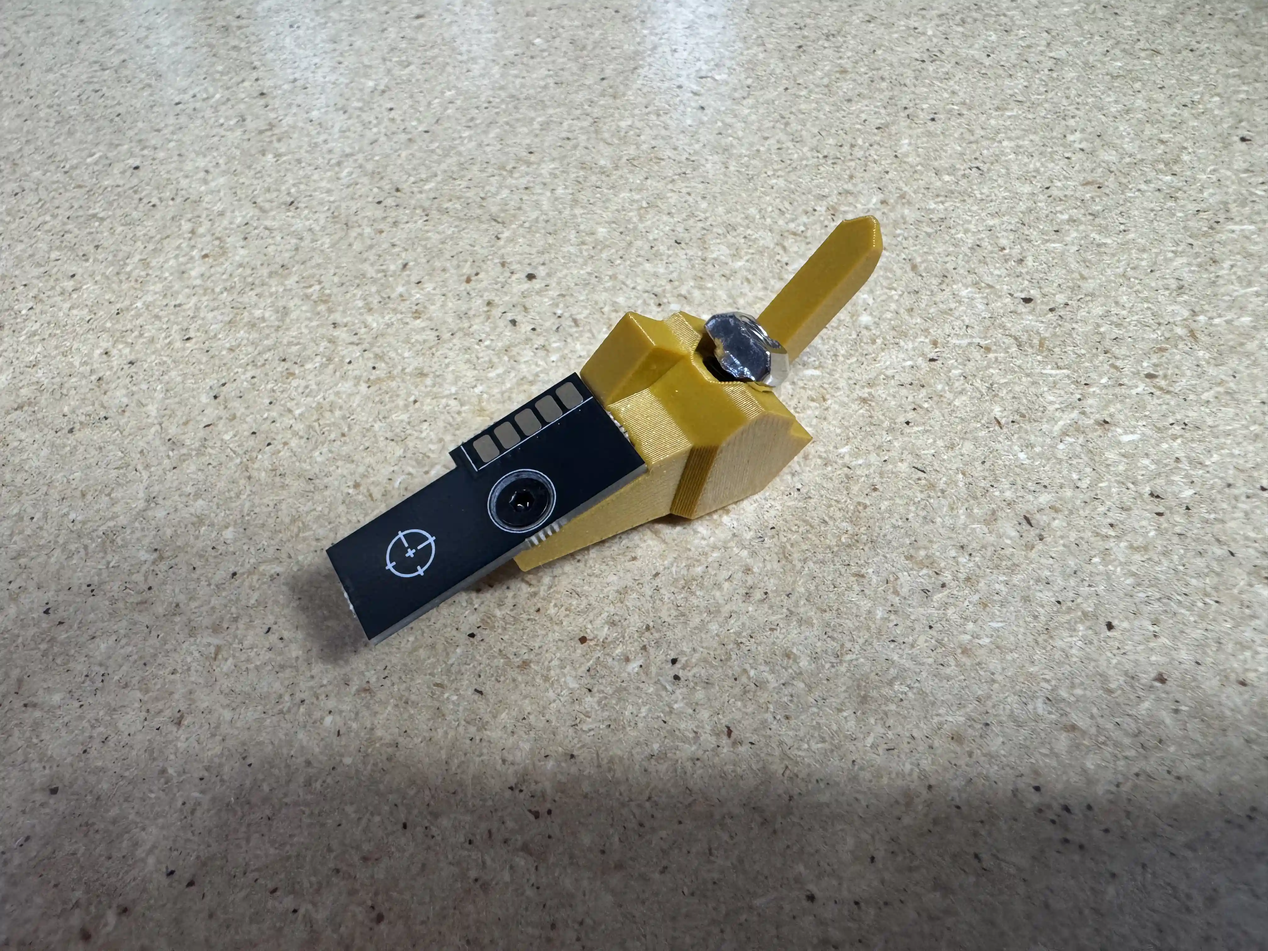
-
Insert
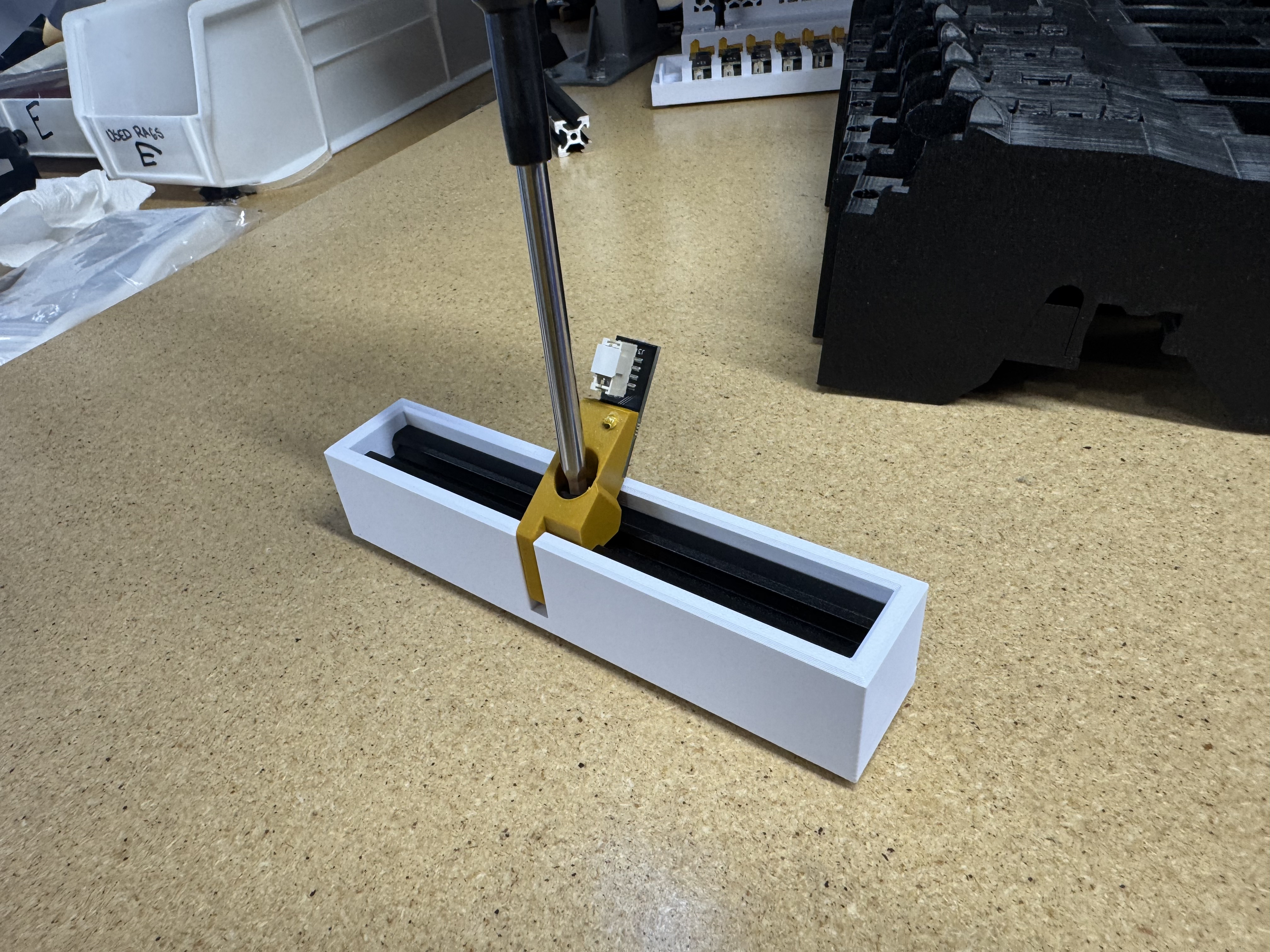
vslot-extrusion-20mm-x-20mm-x-140mmintoslot-centering-jigand securefls-slot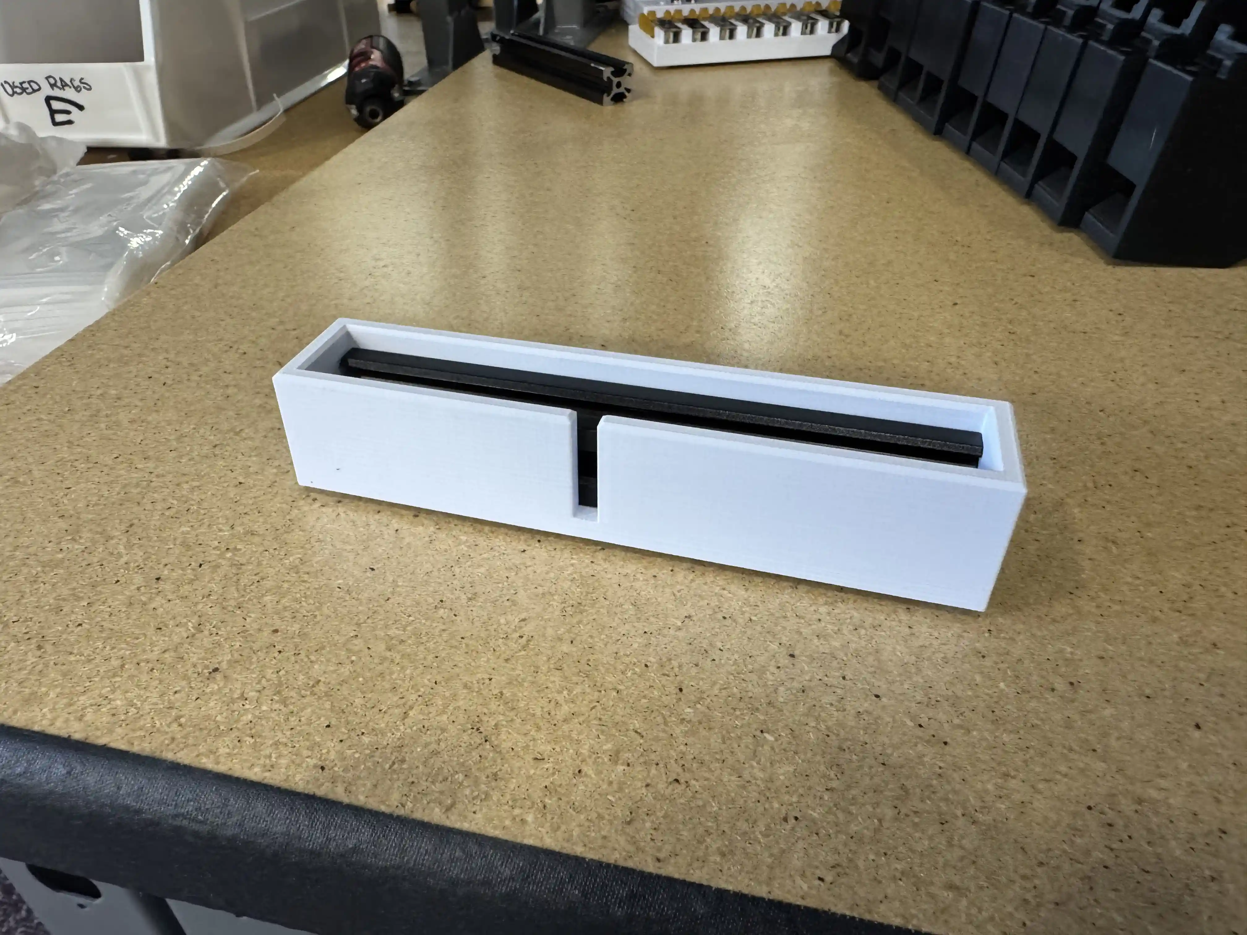
-
Feed
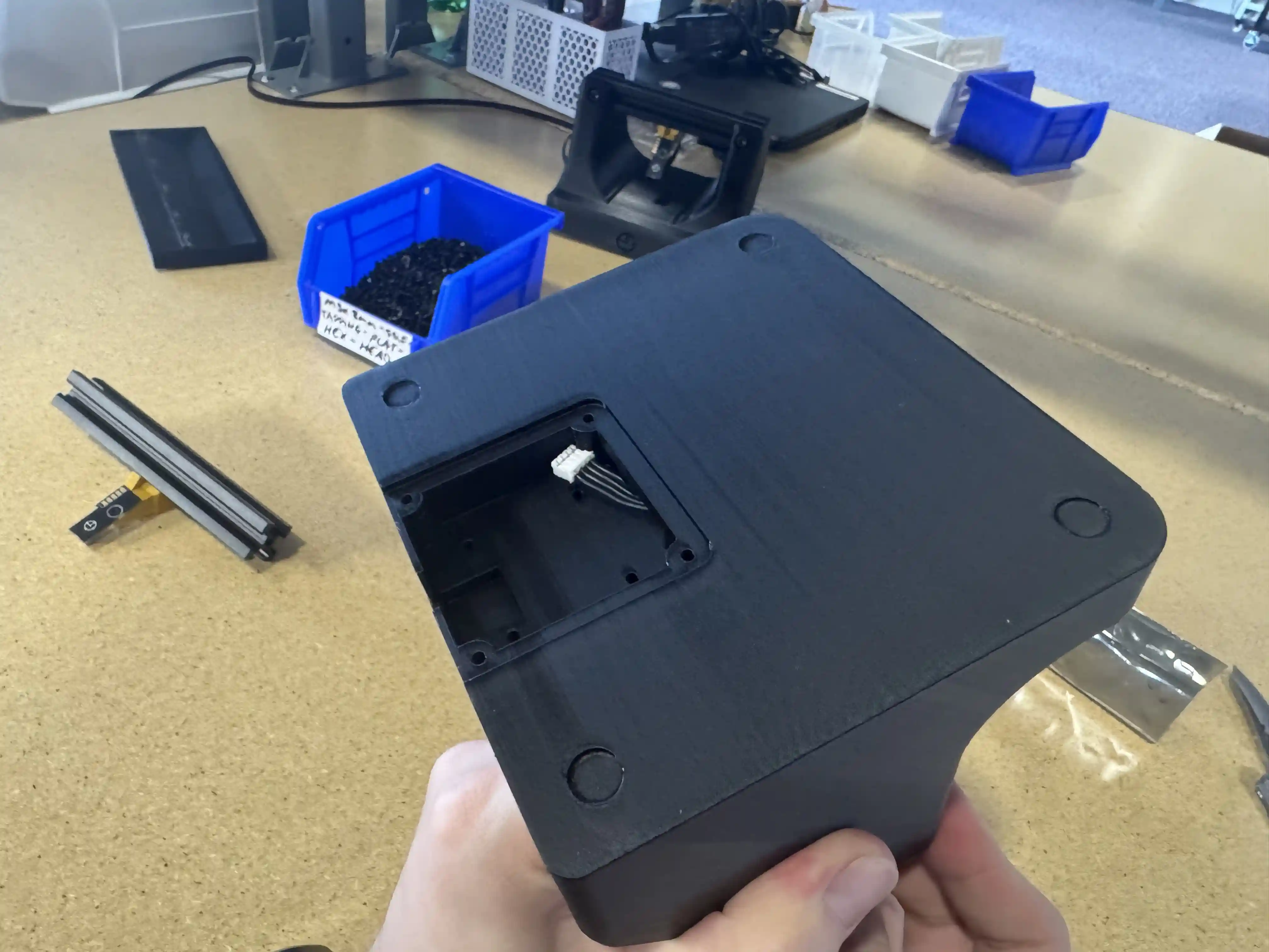
short-photon-harnessthrough channel offls-baseso that it feeds into the cutout at the bottom of the base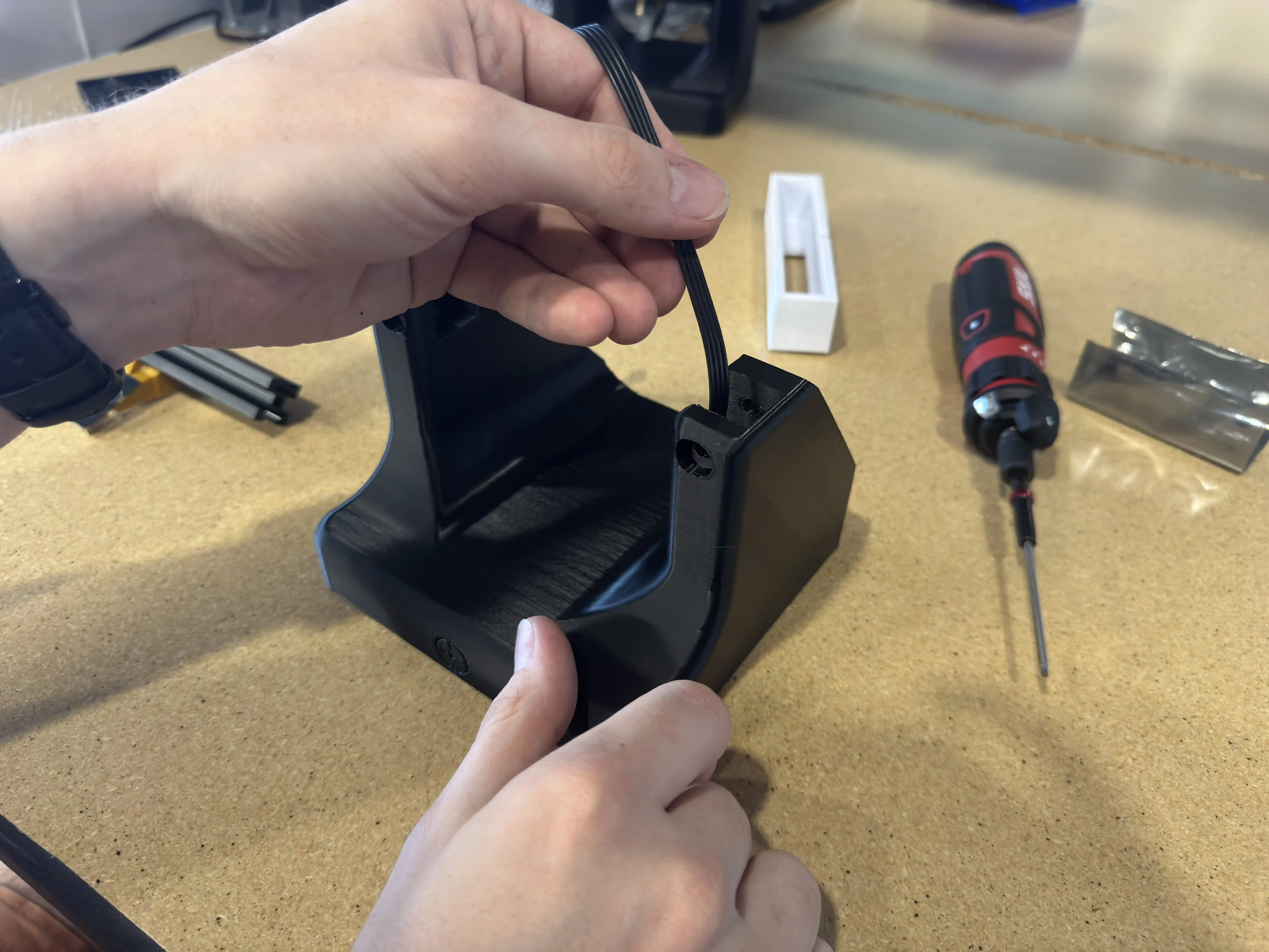
-
Plug
short-photon-harnessintofeeder-slotPCB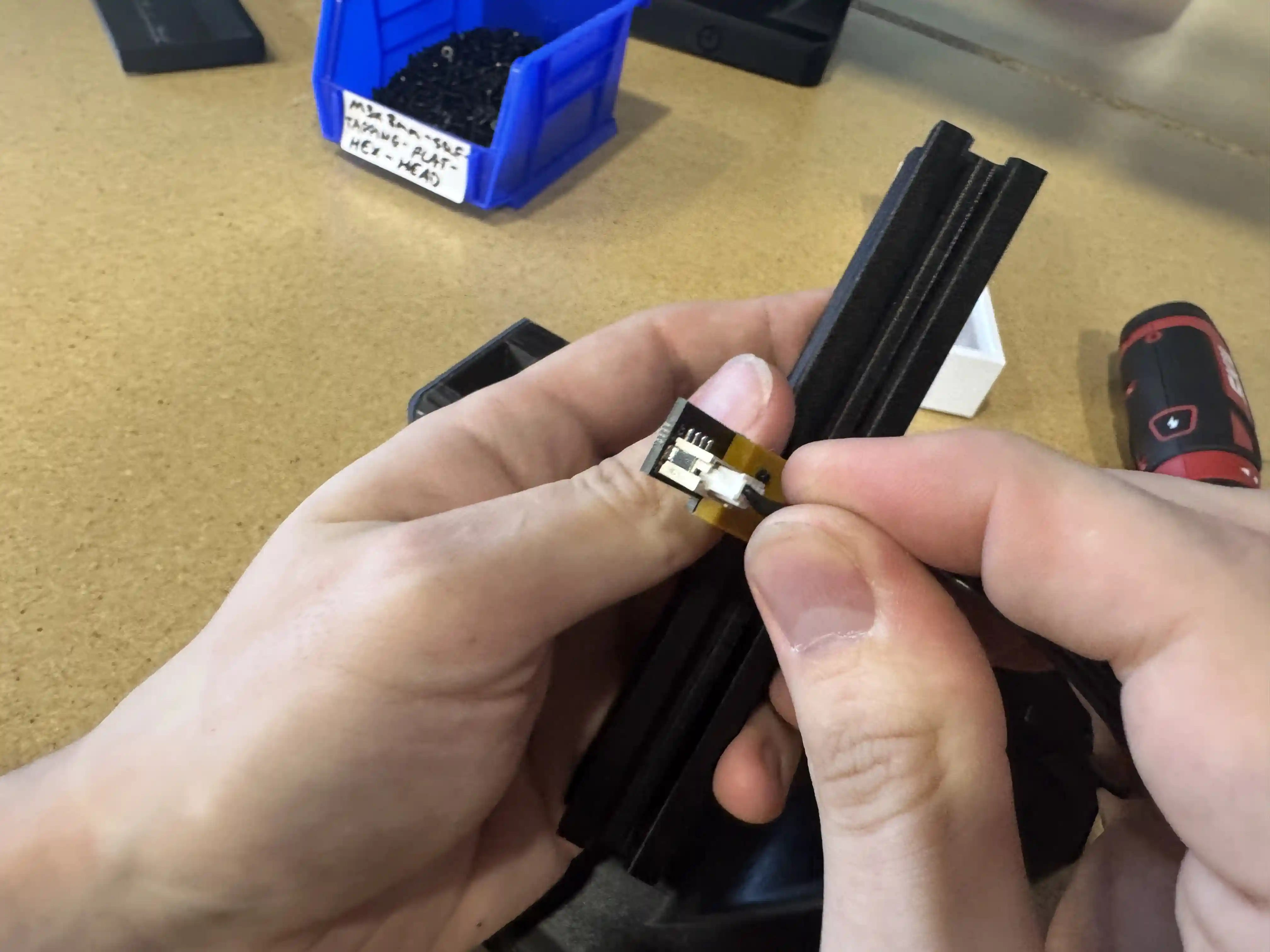
-
Insert
vslot-extrusion-20mm-x-20mm-x-140mmintofls-base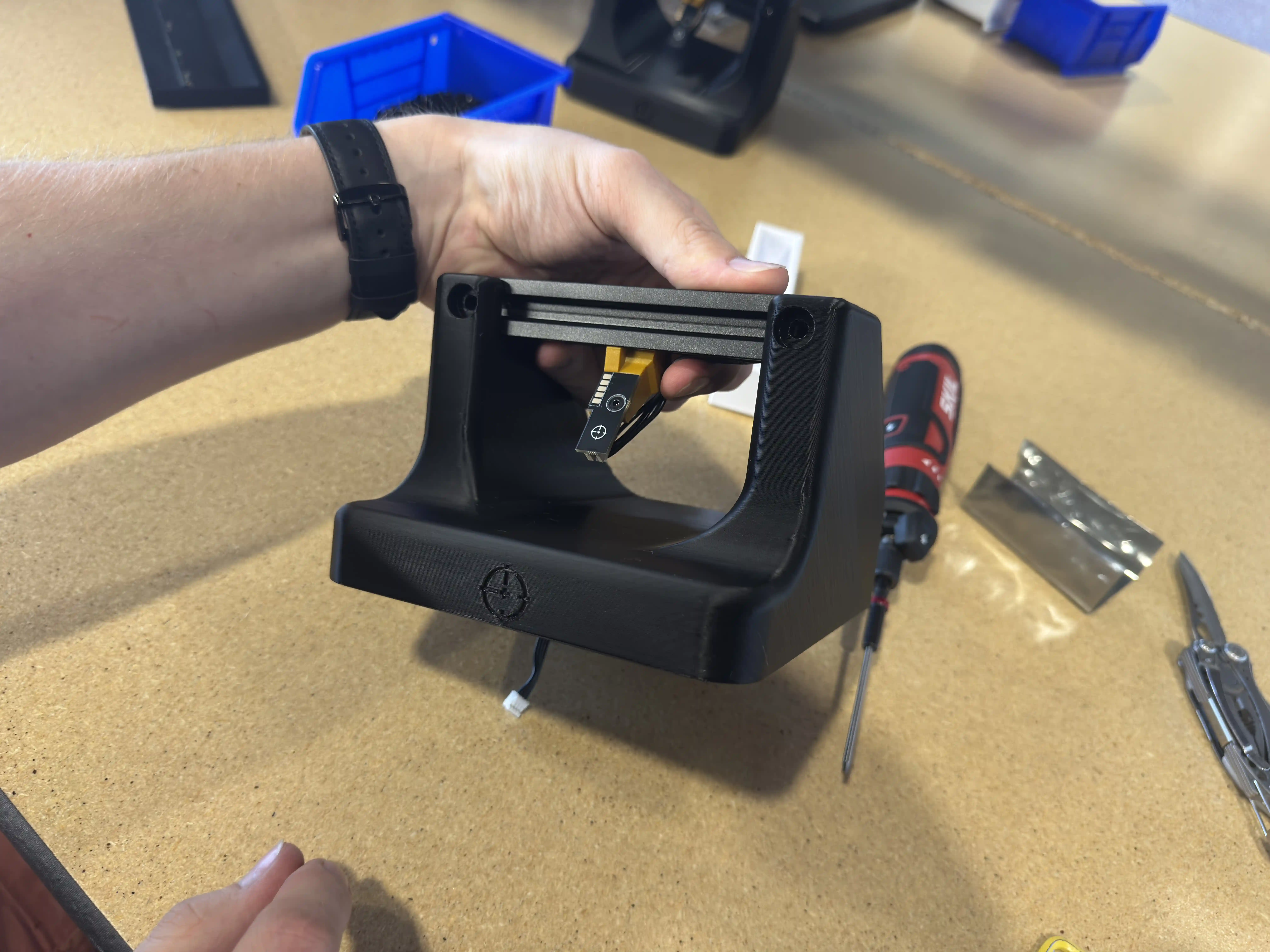
-
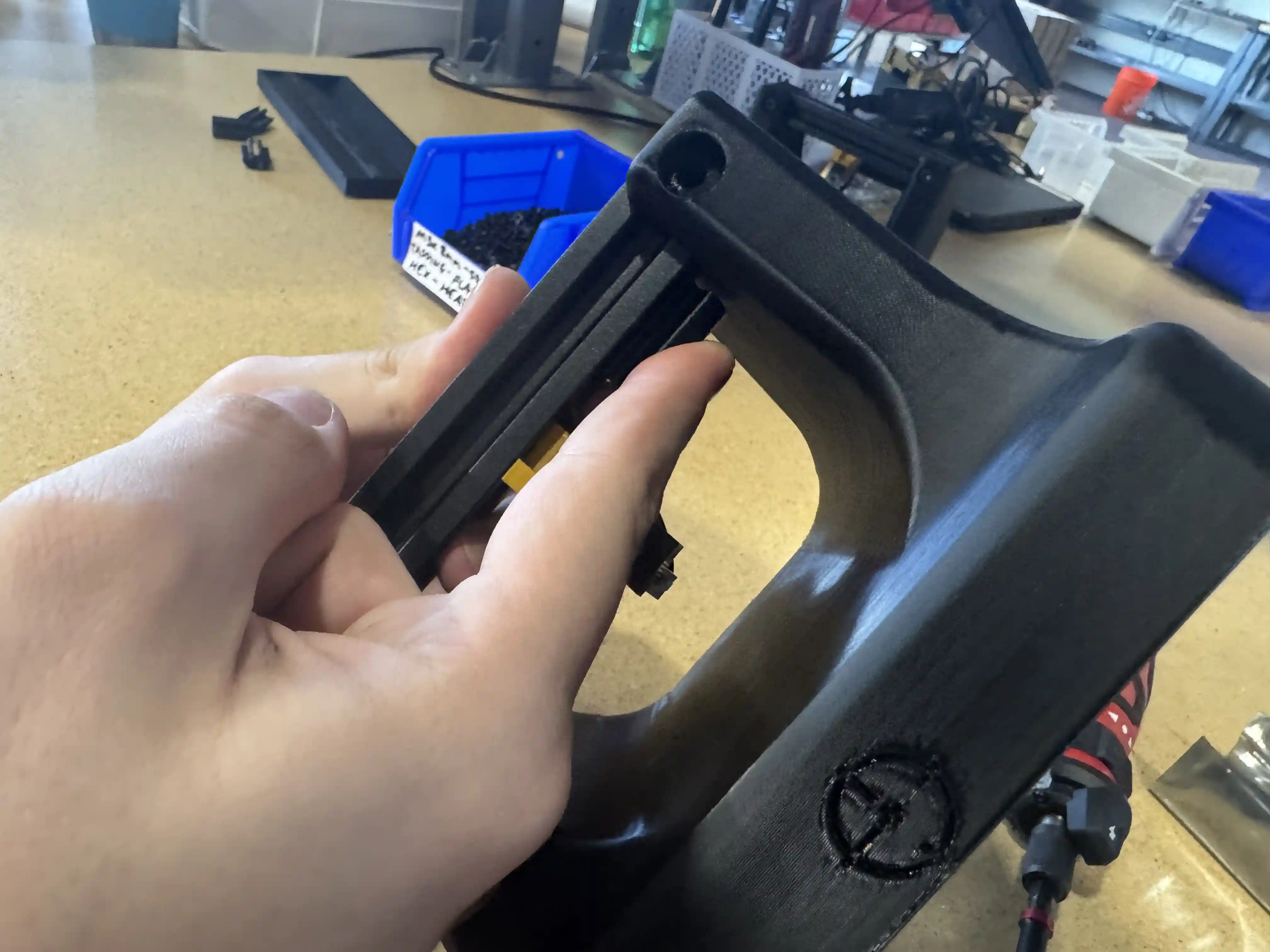
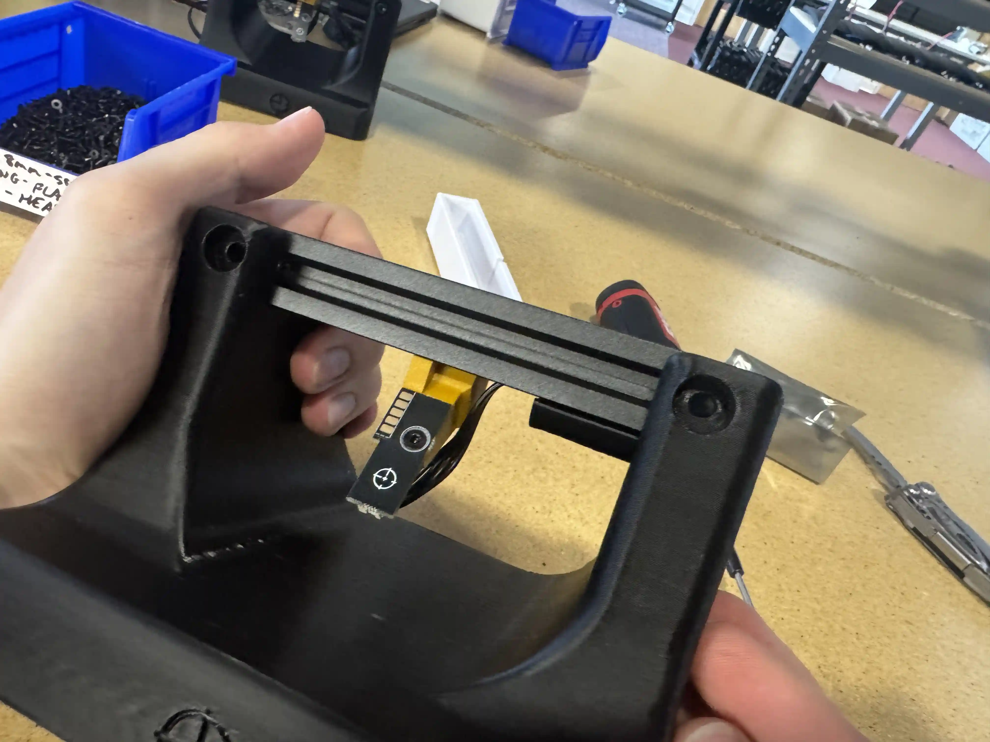
Install
extrusion-cable-clip. Pullshort-photon-harnesstaut and ensure the clip is installed as far right on the extrusion as possible
-
Secure
vslot-extrusion-20mm-x-20mm-x-140mmtofls-basewith 4xm5x10mm-socket-headand 4xm5-tslot-nut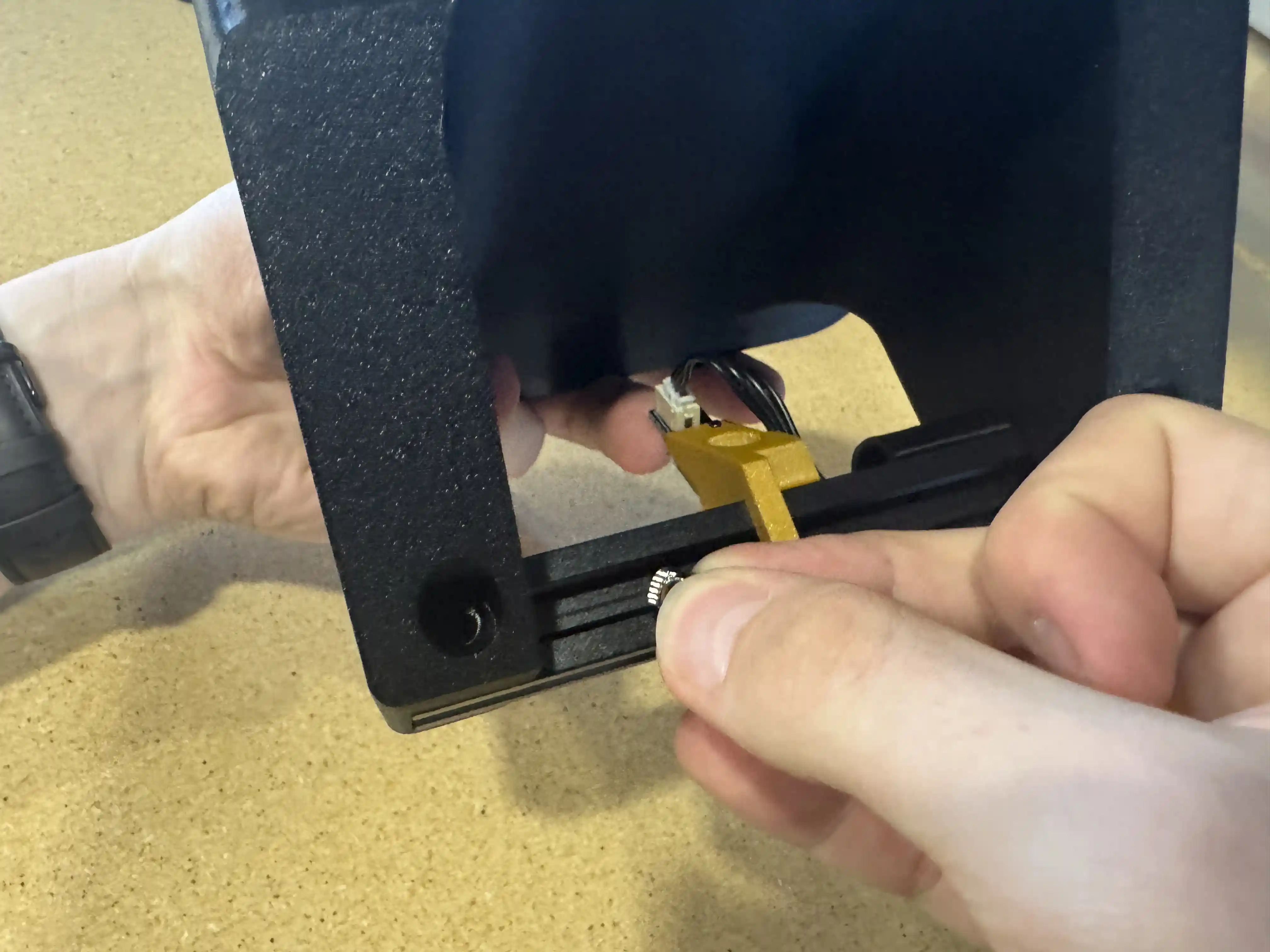
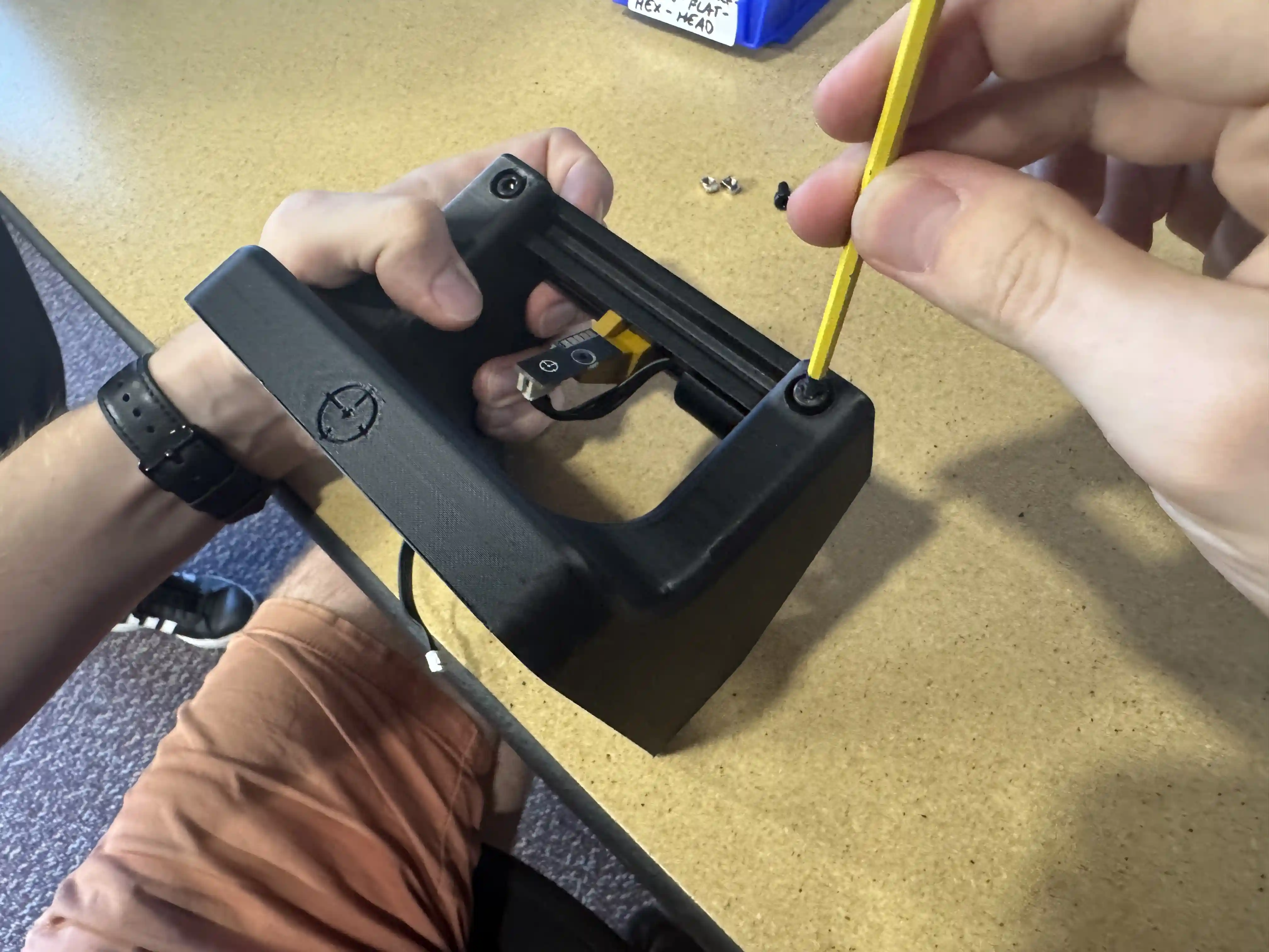
-
Place
power-breakoutPCB into cutout offls-base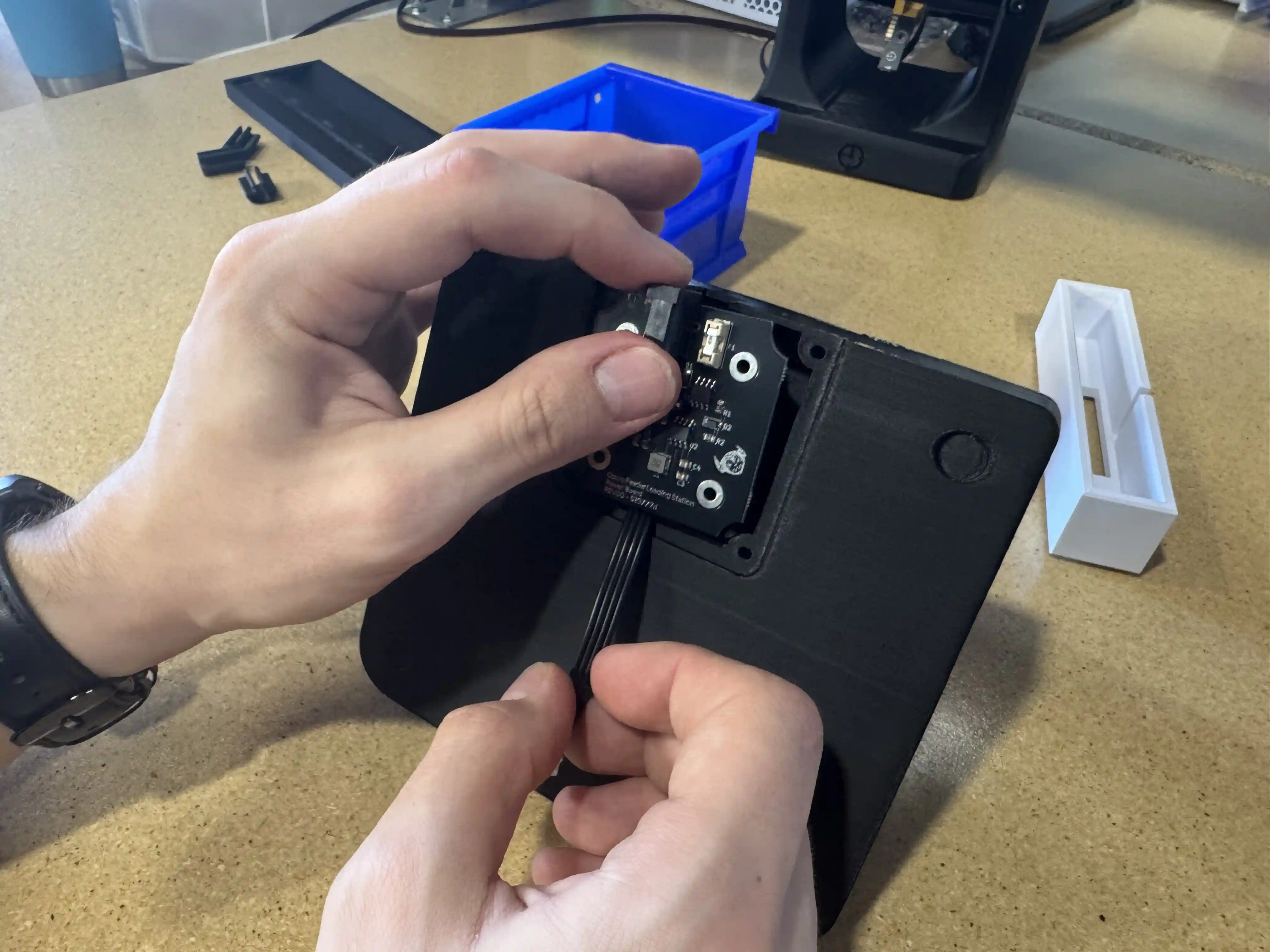
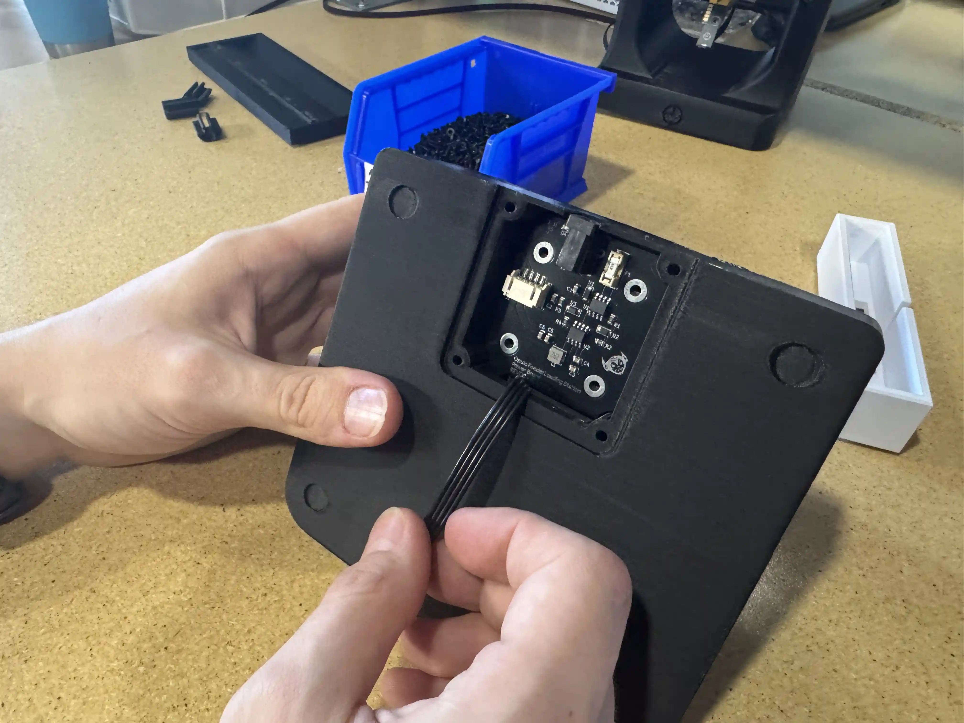
-
Secure
power-breakoutPCB with 4xM3x8mm-self-tapping-flat-hex-head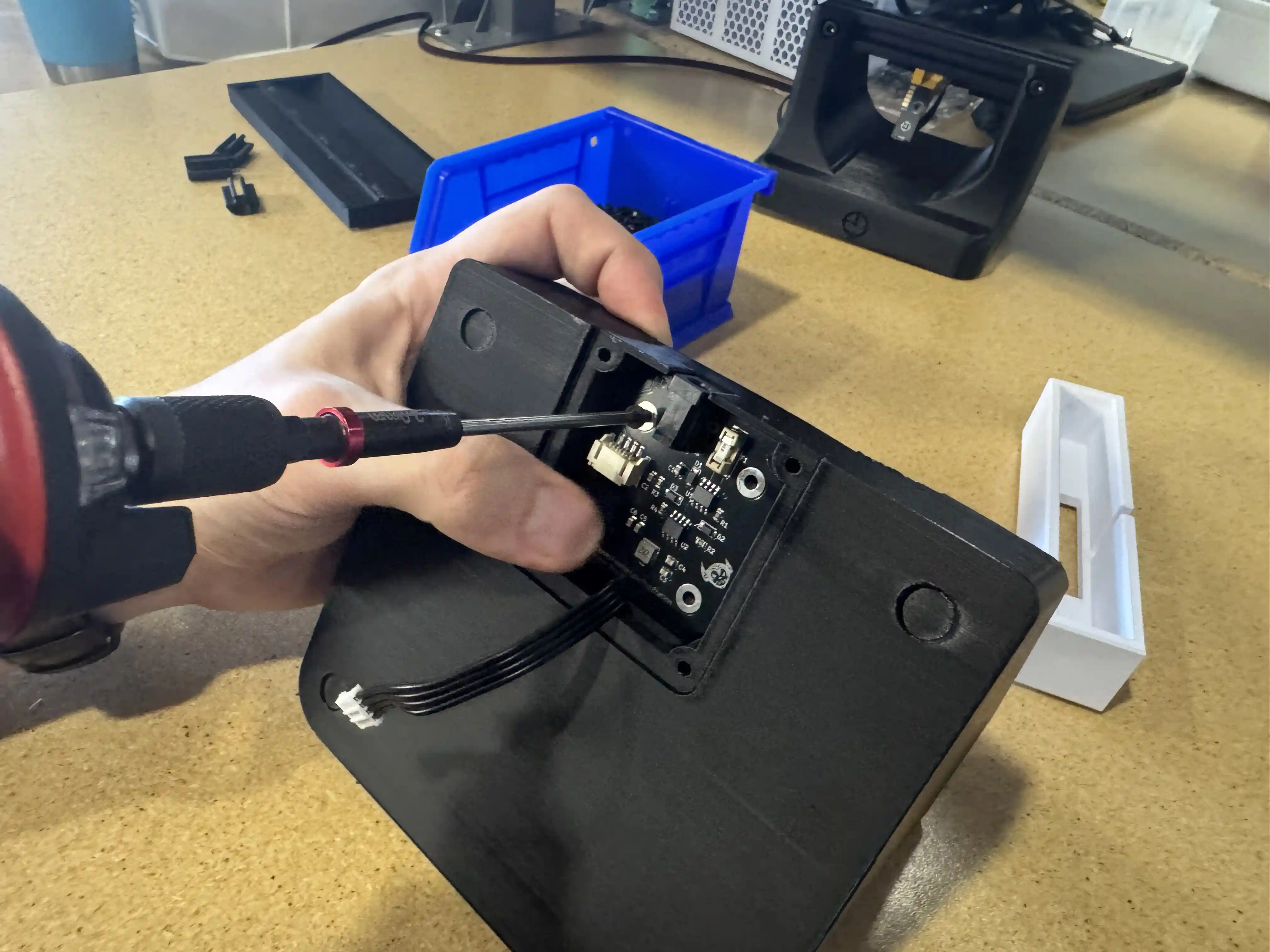
-
Plug
short-photon-harnessintopower-breakoutPCB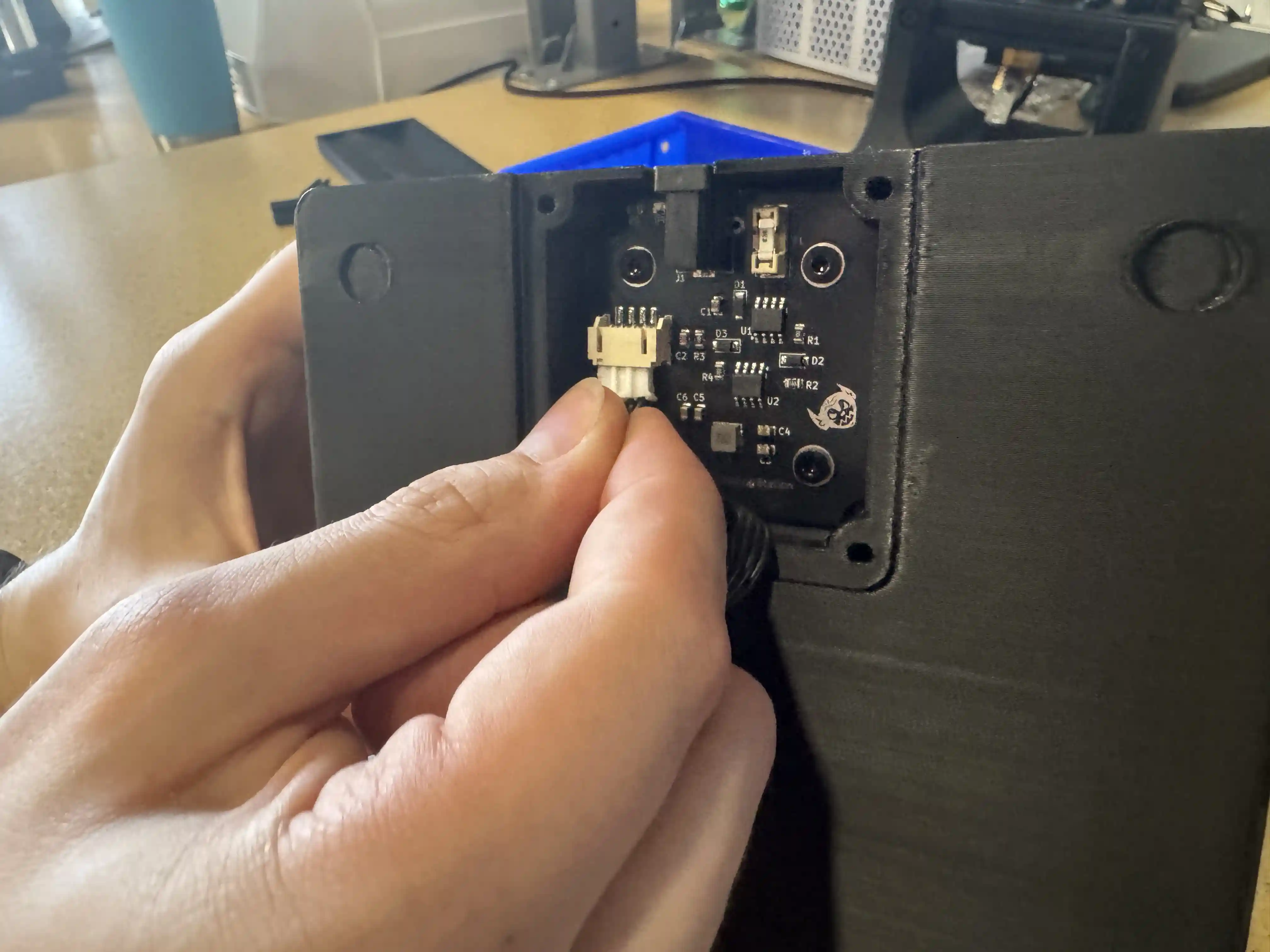
-
Ensure
short-photon-harnesscable is managed and addfls-cover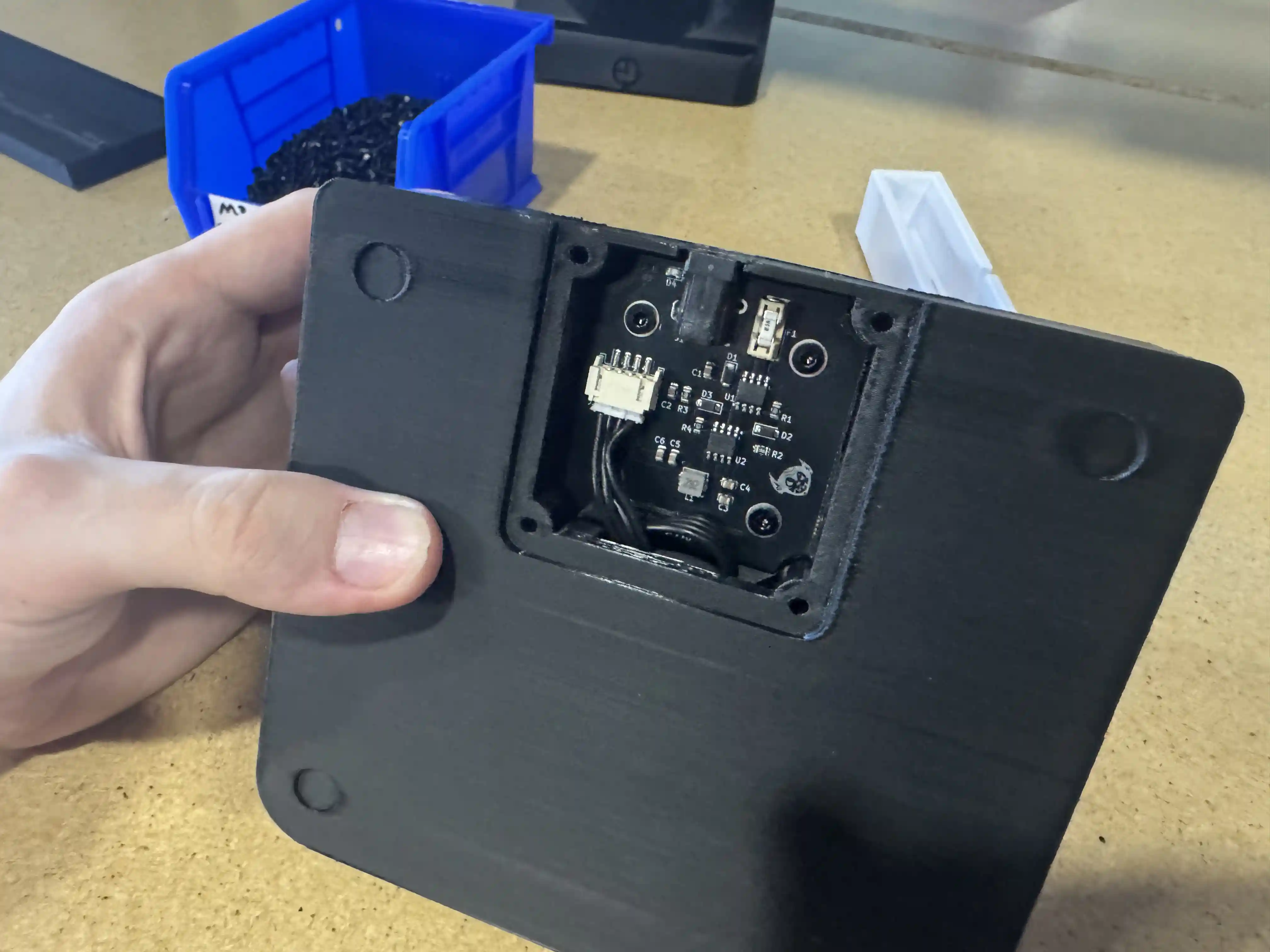
-
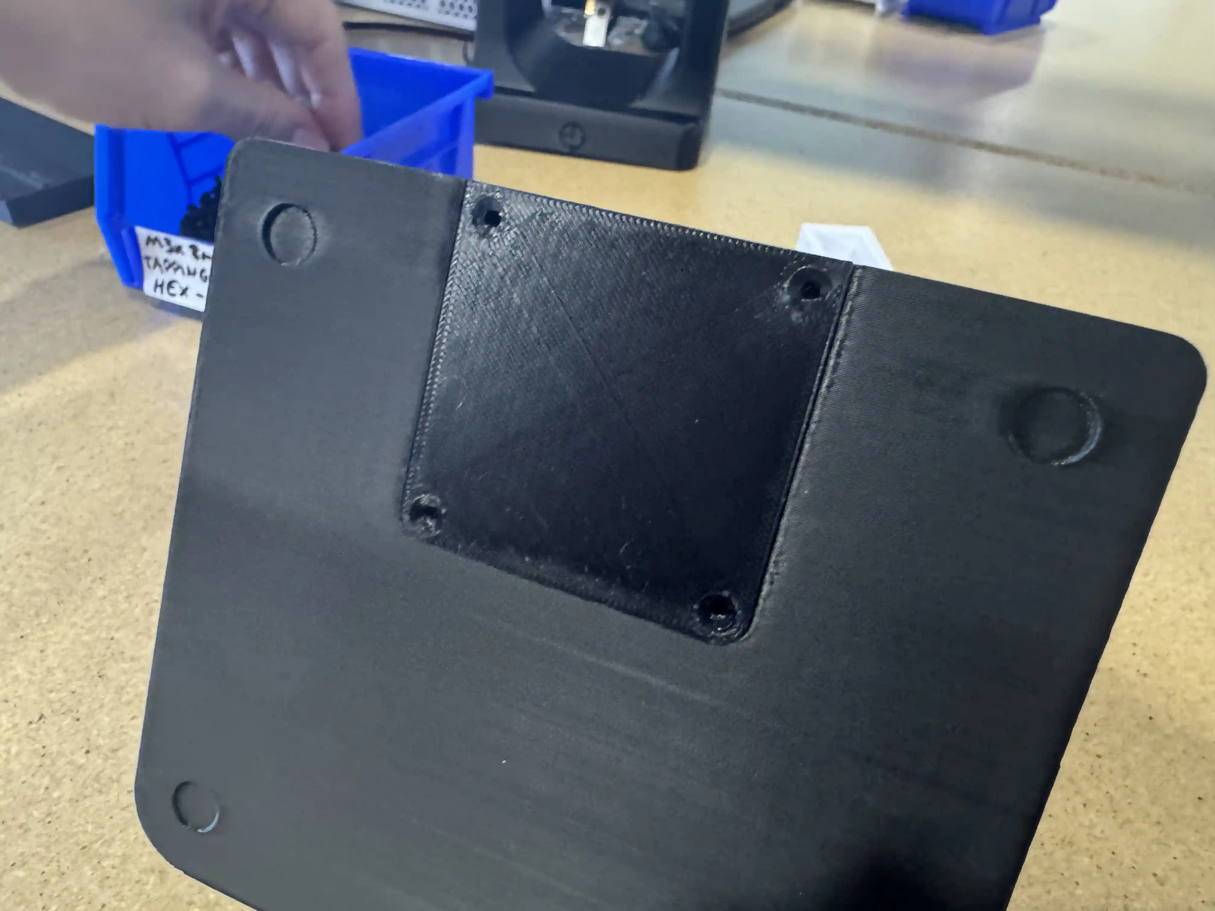
Secure
fls-coverwith 4xM3x8mm-self-tapping-flat-hex-head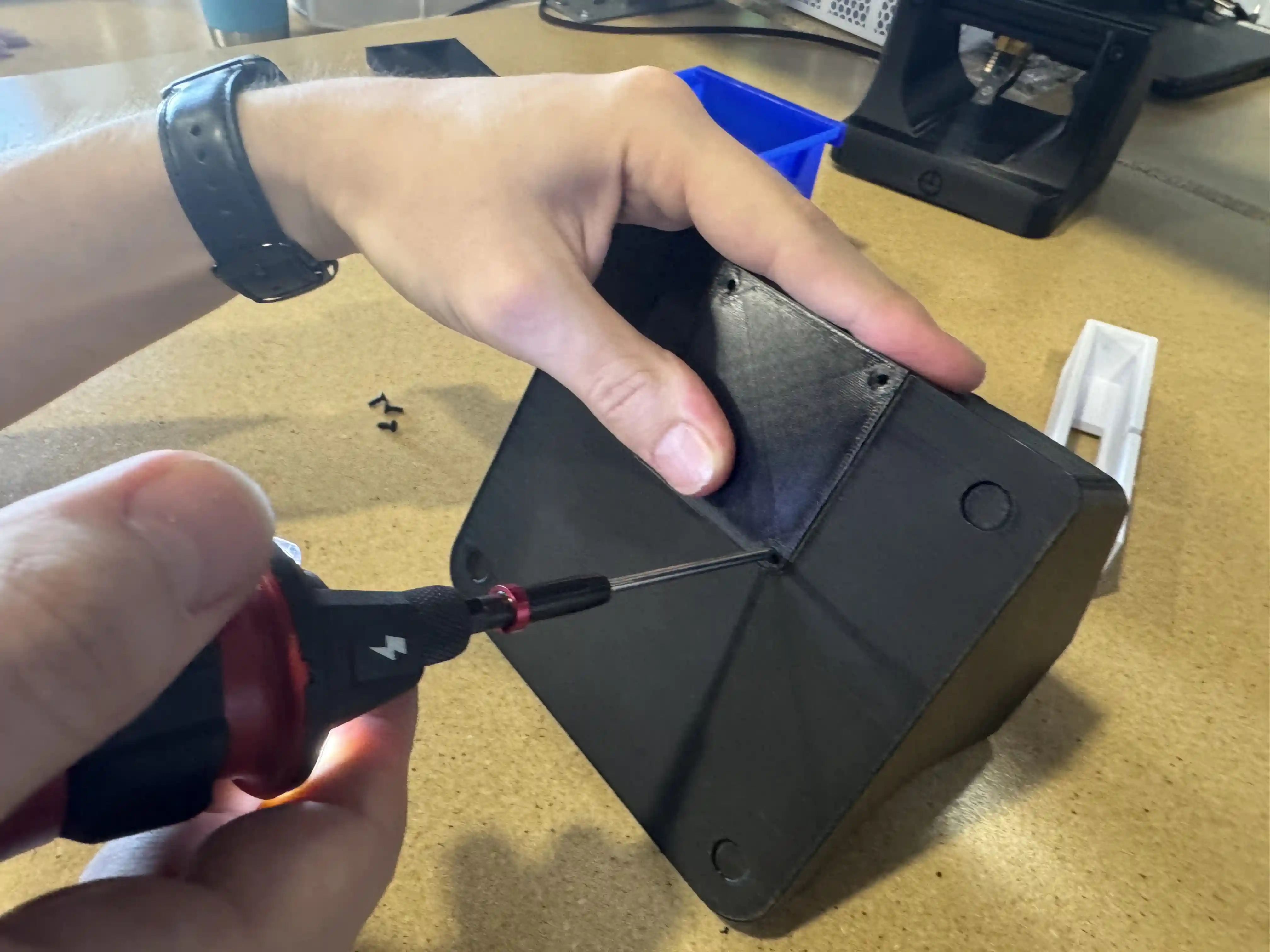
-
Install 4x
rubber-footin the designated cutouts onfls-base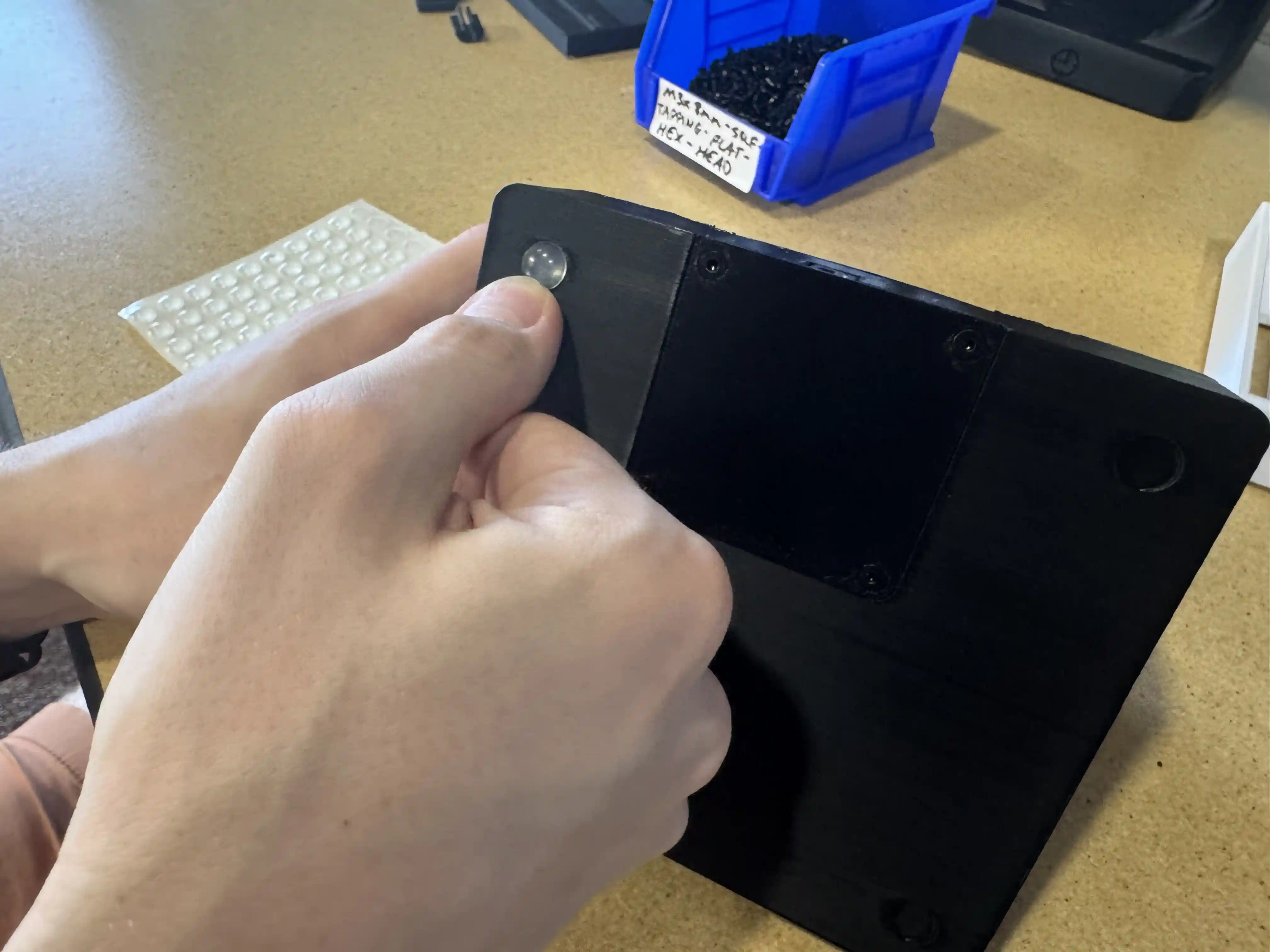
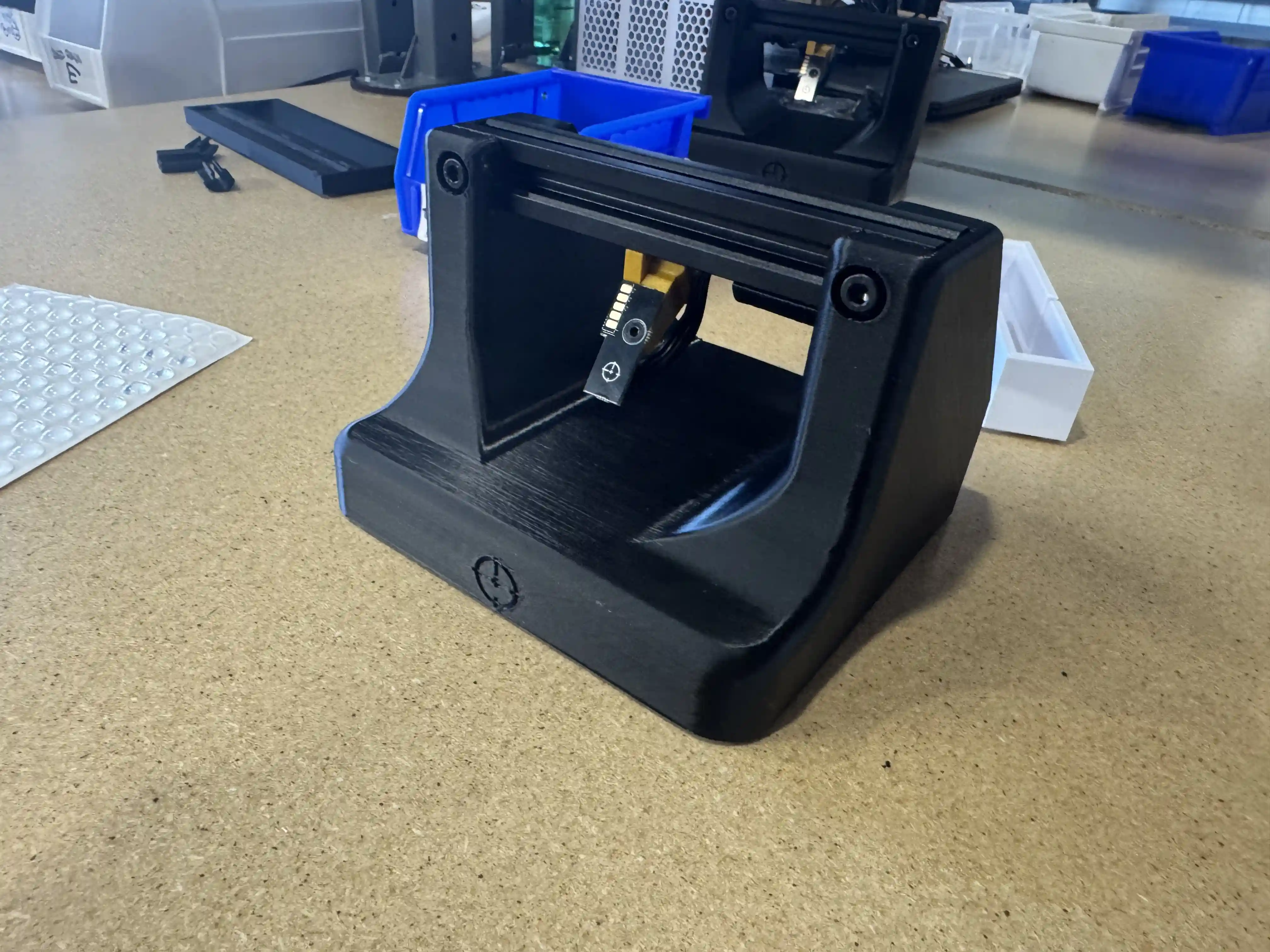
Success
Feeder Loading Station is now fully assembled.